Table of Contents
Advertisement
©2017 Lennox Industries Inc. Dallas, Texas, USA
THIS MANUAL MUST BE LEFT WITH THE OWNER
FOR FUTURE REFERENCE
WARNING
Improper installation, adjustment, alteration, ser vice or
maintenance can cause property damage, personal
injury or loss of life.
Installation and service must be performed by a li censed
professional HVAC installer, service agency or the gas
supplier.
Failure to follow safety warnings and these instruc tions
exactly could result in property damage, dan gerous
operation, serious injury, or death.
Any additions, changes, or conversions required in order
for the appliance to satisfactorily meet the ap plication
needs must be made by a licensed profes sional HVAC
installer (or equivalent) using factory-specified parts.
Do not use this system if any part has been under water.
A flood-damaged appliance is extremely dan gerous.
Immediately call a licensed professional HVAC service
technician (or equivalent) to inspect the system and to
replace all controls and electrical parts that have been
wet, or to replace the system, if deemed necessary.
CAUTION
As with any mechanical equipment, contact with sharp
sheet metal edges can result in personal injury. Take
care while handling this equipment and wear gloves and
protective clothing.
VRF
1
INSTALLATION
INSTRUCTIONS
VVCB Vertical Air Handler
VRF SYSTEMS -- Air Handler
507895-02
01/2019
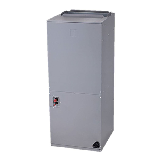
General
The VVCB air handler is designed for indoor installation
only. As shipped, the unit is ready for installation in upflow
and horizontal-right air discharge applications. Field-
configurable for horizontal left-air discharge.
The unit has accessible electrical controls, refrigerant
piping connections and an internally mounted expansion
valve kit. This unit is also equipped with variable speed
blower motor.
Refer to the Product Specification bulletin (EHB) for the
proper use of these indoor units with specific heat pumps,
heat recovery units, mode switching devices, branch
pipes, line sets and controls.
These instructions are intended as a general guide and do
not supersede local codes in any way. Consult authorities
having jurisdiction before installation.
The air handler is shipped from the factory completely
assembled. This unit is provided with flanges for
connecting the supply plenum.
Shipping and Packing List
Check the components for shipping damage. If you
find any damage, immediately contact the last carrier.
Package 1 of 1 contains the following:
1 - Assembled indoor unit
2 - Condensate plugs
2 - Rubber grommets
1 - Water level switch cable
1 - 5/8 to 1/2 adapter (VVCB012)
1 - 3/8 to 1/4 adapter (VVCB012)
1 - Installation manual
5 - Zip ties
1 - Plastic cable clamp & screw
IMPORTANT
The Clean Air Act of 1990 bans the intentional venting
of refrigerant (CFCs, HCFCs and HFCs) as of July 1,
1992. Approved methods of recovery, recycling or
reclaiming must be followed. Fines and/or incarceration
may be levied for noncompliance. These units must be
installed as a part of a matched system as specified in
the Product Specifications (EHB) bulletin.
Advertisement
Table of Contents

Related Manuals for Lennox VVCB


Summary of Contents for Lennox VVCB
- Page 1 VRF SYSTEMS -- Air Handler 507895-02 01/2019 General The VVCB air handler is designed for indoor installation only. As shipped, the unit is ready for installation in upflow and horizontal-right air discharge applications. Field- configurable for horizontal left-air discharge. The unit has accessible electrical controls, refrigerant piping connections and an internally mounted expansion valve kit.
-
Page 2: Safety Requirements
Note - Only Lennox VRF indoor units will work with Lennox VRF outdoor units and associated mechanical equipment. Lennox Mini Split indoor units are similar in appearance but must not be connected to a Lennox VRF refrigerant circuit. Please refer to model numbers to confirm compatibility. Model numbers for Lennex VRF units start with a “V” and model numbers for Lennox Mini-Splits start with a “M”. - Page 3 Dimensions - inches (mm) Upflow Position Shown for Small Box 012-030 Dimension 012-030 inches 45-3/4 1162 19-3/4 17-7/8 21-5/8 13-3/4 18-1/2 20-3/4...
- Page 4 Dimensions - inches (mm) Upflow Position Shown for Big Box 036 - 060 Dimension 036-060 inches 53-3/4 1365 19-1/2 19-1/2 20-3/8 22-3/4...
-
Page 5: Service & Maintenance
Clearances AIRFLOW ” ≥ 39 ≥ 39 ” (1000 mm) (1000 mm) HORIZONTAL INSTALLATION ” ≥ 7 (200 mm) ≥ 7 ” ” ≥ 7 ” ≥ 39 (200 mm) (200 mm) (1000 mm) NOTE: All dimensions shown in inches. VERTICAL INSTALLATION Note - Minimum front service access - 24 inches (610 mm) minimum. -
Page 6: Parts Identification
Parts Identification Straps Horizontal Drain Pan Drip Shield Baffle Gas Line Connection Liquid Line Connection Electronic Expansion Valve (EEV) Auxiliary Horizontal Drain Connection Strainer Vertical Drain Pan Primary Drain Connection Auxiliary Upflow Drain Connection Figure 2. Parts Identification... - Page 7 Indoor Unit Placement IMPORTANT This unit is approved for installation clearance to WARNING combustible material as stated on the unit rating plate. Use the provided and specified components when Accessibility and service clearances must take installing equipment. Failure to do so may result in precedence over combustible material clearances.
-
Page 8: Installation
Position the Unit Installation DANGER It is important to locate the unit where it can be accessed Units must not be installed where they may be exposed for service in the future. Refer to unit dimensions on Page to potentially explosive or flammable atmosphere. If this 3 for exact locations of suspension brackets, return air instruction is not followed and supply air openings. -
Page 9: Upflow Application
Horizontal Application CAUTION 1. Determine knockouts required drain line Do not place items which may be damaged by water connections. under or around the indoor unit. 2. With access door removed, remove drain line opening to install drain lines. Upflow Application 3. -
Page 10: Sensor Description
Horizontal-Left Conversion 1. Remove the top panel and the blower section panel. 2. Remove the T-2, T-2A and T-2B sensors from the sleeves. The sensors look similar; label the sensors so that they can be reinstalled to the proper locations. Sensor black cable,... - Page 11 Figure 11. Route Wiring Harness Through Coil and Figure 9. Coil Rotated 180° Into Electrical Compartment 13. Reinstall the EEV motor. 20. Turn the coil compartment cover 180° and reattach to 14. Route wiring harness through coil, past the blower the unit cabinet.
-
Page 12: Refrigerant Piping Connections
Field provided piping consists of two HVAC/R rated copper Refrigerant Piping Connections lines connected to the indoor unit. Final equipment connections must be brazed connections. WARNING Compression or other types of fittings are not permitted for Refrigerant leaks are unlikely; however, if a refrigerant final connections. -
Page 13: Brazing Refrigerant Lines
1. The seal on the unit refrigerant piping connections Brazing Refrigerant Lines should remain in place until the last possible moment. This will prevent dust or moisture from getting into the Refrigerant lines must be connected by a qualified refrigerant piping before it is connected. technician in accordance with established procedures. - Page 14 6. Route the drain line to the outside or to an Condensate Piping Connections appropriate drain. Drain lines must be installed The air handler is provided with ¾” NPT condensate so they do not block service access to the front drain connections.
-
Page 15: Duct System
Sloping The Unit IMPORTANT Make sure the unit is sloped (similar to the slope shown in If an elbow is included in the plenum close to the unit, it Figure 14) (horizontal or vertical) so that the drain pan will must not be smaller than the dimensions of the supply empty completely without water standing in the pan. -
Page 16: Wiring Connections
P and Q. Use specified wiring and cable to make electrical 4. The VVCB unit receiver/display must be field- connections. Clamp cables securely and make sure that connected and mounted. If it is necessary to position connections are tight to avoid strain on wiring. Insecure... - Page 17 Indoor units and mode selection boxes on the same maintenance purposes. Indoor unit and mode selection refrigeration circuit should have a common power supply box power supply MUST not be taken from the outdoor but must have an independent disconnect switch installed unit.
- Page 18 Outdoor unit Outdoor unit Outdoor unit (sub1 unit) (main unit) (sub2 unit) H1 H2 Outdoor Unit Communication Terminal Block (H1 H2 (H1 H2 (H1 H2 (PQ) (PQ) (PQ) (PQ) MS Box Communication Terminal Block HA HB 12V COM P (PQ) (PQ) Indoor Unit Communication Terminal Block Ground cable shield...
- Page 19 Outdoor unit Outdoor unit Outdoor unit (main unit) (sub1 unit) (sub2 unit) (H1 H2 (H1 H2 (H1 H2 K1 K2 H1 H2 Outdoor Unit Communication Terminal Block (PQ) HA HB 12V COM P Indoor Unit Communication Terminal Block Ground cable shield (PQ) to Indoor Unit chassis Install a terminating resistor ( 120) at the last indoor unit terminals P and Q of the daisy chain.
- Page 20 Middle of evaporator Sensor Water level switch DC fan motor error Emergency stop ALARM Warning lamp Remote off EEPROM failure NOTE - Typical wiring diagram. Refer to wiring diagram on the unit for actual wiring. Figure 18. VVCB Typical Wiring Diagram...
-
Page 21: Electrical Data
Electrical Data VVCB012H4 Blower Speed Blower Motor Minimum Maximum Input Description Full Load Circuit Overcurrent Medium High Amps Ampacity Protection Volt Btuh 5 kW V8EH0050P-1P (13P59) 208 12,800 24.5 • • • 14,300 25.5 • • • 15,700 26.5 • •... - Page 22 VVCB030H4 Input Blower Motor Minimum Maximum Blower Speed Description Full Load Circuit Overcurrent Volt Btuh Medium High Amps Ampacity Protection 5 kW V8EH0050P-1P (13P59) 208 12,800 26.8 • • • 14,300 27.8 • • • 15,700 28.8 • • • 17,100 29.8 •...
- Page 23 VVCB048H4 Minimum Maximum Single Point Blower Input Circuit Overcurrent Blower Speed Power Source Motor Ampacity Protection Description Full Minimum Maximum Load Volt Btuh Ckt 1 Ckt 2 Ckt 1 Ckt 2 Circuit Overcurrent Low Medium High Amps Ampacity Protection 5 kW V8EH0050P-1P 12,800 28.3...
- Page 24 VVCB54H4 Minimum Maximum Single Point Blower Input Circuit Overcurrent Blower Speed Power Source Motor Ampacity Protection Description Full Minimum Maximum Load Volt Btuh Ckt 1 Ckt 2 Ckt 1 Ckt 2 Circuit Overcurrent Low Medium High Amps Ampacity Protection 5 kW V8EH0050P-1P 12,800 30.2...
- Page 25 VVCB60H4 Minimum Maximum Single Point Blower Input Circuit Overcurrent Blower Speed Power Source Motor Ampacity Protection Description Full Minimum Maximum Load Volt Btuh Ckt 1 Ckt 2 Ckt 1 Ckt 2 Circuit Overcurrent Low Medium High Amps Ampacity Protection 5 kW V8EH0050P-1P 12,800 30.5...
-
Page 26: Airflow Performance
Airflow Performance External Static Pressure-In. W. G. [Pa] Model Motor Nominal 0(0) 0.1(25) 0.2(50) 0.3(75) 0.4(100) 0.5(125) 0.6(150) 0.7(175) 0.8(200) Cooling Number Speed 1 Ton 1.5 Ton 2 Ton 2.5 Ton 1000 3 Ton 1050 1200 1120 4 Ton 1360 1650 1260 5 Ton... -
Page 27: Air Filter
Soot damage may occur with filters in place, when certain types of candles, oil lamps or standing pilots are burned. The VVCB air filter is field-provided and installed. Follow these guidelines when selecting and installing the filter. FILTER RAILS •... -
Page 28: Mounting The Receiver
Mounting the Receiver The VVCB unit receiver must be field-connected and mounted. Mounting slots are available inside of the electrical control box. 1. Remove receiver from accessories package. 2. Insert the two fixed plastic mounting brackets on the back of the receiver into the two slots inside of the electrical control box and slide to secure it. - Page 29 Network Address and Commissioning After the system has been installed, each indoor unit must be assigned an address as part of the commissioning procedure. Spot Check Instructions Use the Spot Check Performance Identification Table below and the Manual button on the unit receiver to view diagnostic information the indoor unit.
-
Page 30: Troubleshooting
Troubleshooting Digital Display Make note of the code (E1, EE, etc.), then reset the display by pressing the ON/OFF button on the unit controller. The indoor unit is equipped with a receiver that has a digital Press the ON/OFF button a second time to reapply power display that provides an error code. - Page 31 Technical Support 1-844-GET-VRF1 (1-844-438-8731) vrftechsupport@lennoxind.com www.LennoxVRF.com Download the app from the Apple App Store or the Google Play store.