Table of Contents
Advertisement
S e r v i c e L i t e r a t u r e
WARNING
To prevent serious injury or death:
1- Lock-out/tag-out before performing maintenance.
2- If system power is required (e.g., smoke detector
maintenance), disable power to blower, remove
fan belt where applicable, and ensure all
controllers and thermostats are set to the "OFF"
position before performing maintenance.
3- Always keep hands, hair, clothing, jewelry, tools,
etc., away from moving parts.
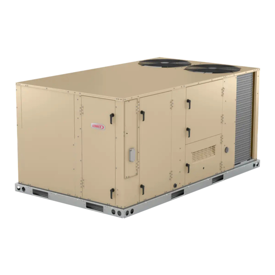
The LGT092H-150H units are configure to order units
(CTO) with a wide selection of factory-installed options.
Units are available in 130,000, 180,000 Btuh or 240,000
Btuh (38.1, 52.7 or 70.3 kW) heating inputs. Gas heat
sections are designed with aluminized steel tube heat ex-
changers with stainless steel as an option.
Cooling capacities range from 7.5 to 12.5 tons. All units
are equipped with two compressors.
All models are equipped with direct drive blowers. The
blower will operate at lower speeds when demand is low
and increase to higher speeds when demand is high. The
following examples show the model numbers of tenton
units with all available blower options:
LGT120H4E Single Zone MSAV Direct Drive
LGT12w are equipped with all aluminum condenser
coils with one two stage scroll compressor and one
single stage compressor.. Units can operate from 0°F
to 125°F.
Units are also designed for R410A refrigerant. See unit
nameplate. Operating pressures and pressure switch set-
tings are significantly higher than R22 charged units. Ser-
vice equipment must be rated for R410A.
All LGT units are designed to accept any of several differ-
ent energy management thermostat control systems with
minimum field wiring. Factory or field provided control op-
tions connect to the unit with jack plugs. When "plugged
in" the controls become an integral part of the unit wiring.
Information contained in this manual is intended for use
by qualified service technicians only. All specifications are
subject to change. Procedures outlined in this manual are
presented as a recommendation only and do not super-
sede or replace local or state codes.
If the unit must be lifted for service, rig unit by attaching
four cables to the holes located in the unit base rail (two
holes at each corner). Refer to the installation instructions
for the proper rigging technique.
UNIT INFORMATION
UNIT INFORMATION
100074
LGT092H through 150H
Page 1
WARNING
Improper
installation,
service or maintenance can cause property damage,
personal injury or loss of life. Installation and service
must be performed by a licensed professional HVAC
installer or equivalent, service agency, or the gas
supplier
CAUTION
As with any mechanical equipment, contact with
sharp sheet metal edges can result in personal
injury. Take care while handling this equipment and
wear gloves and protective clothing.
Table of Contents
Options / Accessories . . . . . . . . . . . . . . . . . . . . . Page 2
Specifications . . . . . . . . . . . . . . . . . . . . . . . . . . . . Page 5
Blower Tables . . . . . . . . . . . . . . . . . . . . . . . . . . . Page 8
Electrical Data . . . . . . . . . . . . . . . . . . . . . . . . . . Page 11
Parts Arrangement . . . . . . . . . . . . . . . . . . . . . . . Page 13
I-Unit Components . . . . . . . . . . . . . . . . . . . . . . . Page 14
II-Placement and Installation . . . . . . . . . . . . . . . Page 29
III-Charging . . . . . . . . . . . . . . . . . . . . . . . . . . . . . . Page 29
IV-Start Up - Operation . . . . . . . . . . . . . . . . . . . . Page 34
VI-Maintenance . . . . . . . . . . . . . . . . . . . . . . . . . . Page 39
VIII-Direct Drive Supply Air Blower . . . . . . . . . . Page 49
IX-Staged Supply Air Operation . . . . . . . . . . . . Page 50
LGT SERIES
7.5 to 12.5 ton
adjustment,
alteration,
Advertisement
Table of Contents

Related Manuals for Lennox LGT Series


Summary of Contents for Lennox LGT Series
-
Page 1: Table Of Contents
LGT SERIES UNIT INFORMATION UNIT INFORMATION 7.5 to 12.5 ton 100074 S e r v i c e L i t e r a t u r e LGT092H through 150H WARNING To prevent serious injury or death: 1- Lock-out/tag-out before performing maintenance. -
Page 2: Options / Accessories
OPTIONS / A C C ESSORIES Unit Model No Catalog Item Description Number 092 102 120 150 COOLING SYSTEM 22H54 Condensate Drain Trap Copper 76W27 Drain Pan Overflow Switch 21Z07 HEATING SYSTEM Bottom Gas Piping Kit 54W95 Combustion Air Intake Extensions 19W51 Gas Heat Input 130,000 Btuh... - Page 3 OPT IONS / A C C ESSORIES Unit Model No Catalog Item Description Number 092 102 120 150 INDOOR AIR QUALITY Air Filters Healthy Climate High Efficiency Air Filters MERV 8 50W61 ® 20 x 25 x 2 (Order 4 per unit) MERV 13 52W41 MERV 16...
- Page 4 OPT IONS / A C C ESSORIES Unit Model No Catalog Item Description Number 092 102 120 150 ECONOMIZER High Performance Economizer (Approved for California Title 24 Building Standards / AMCA Class 1A Certified) High Performance Economizer 20U80 Downflow or Horizontal - Includes Outdoor Air Hood and Downflow Barometric Relief Dampers with Exhaust Hood Order Horizontal Barometric Relief Dampers separately Horizontal Barometric Relief Dampers...
-
Page 5: Specifications
S PEC IFIC ATIONS M SAV M O D ELS General Data Nominal Tonnage 7.5 Ton 8.5 Ton 10 Ton 12.5 Ton Efficiency Type High High High High Model Number LGT092H4E LGT102H4E LGT120H4E LGT150H4E Blower Type DirectPlus™ DirectPlus™ DirectPlus™ DirectPlus™ ECM Direct Drive ECM Direct Drive ECM Direct Drive... - Page 6 S PEC IFIC ATIONS VAV M O D ELS General Data Nominal Tonnage 7.5 Ton 8.5 Ton 10 Ton 12.5 Ton Efficiency Type High High High High Model Number LGT092H4P LGT102H4P LGT120H4P LGT150H4P Blower Type DirectPlus™ DirectPlus™ DirectPlus™ DirectPlus™ ECM Direct Drive ECM Direct Drive ECM Direct Drive ECM Direct Drive...
- Page 7 SP ECIF ICATION S G A S HEAT Heat Input Type Standard Medium High Number of Gas Heat Stages Gas Heating Input - Btuh First Stage 84,500 117,000 156,000 Performance Second Stage 130,000 180,000 240,000 Output - Btuh Second Stage 104,000 144,000 194,000...
-
Page 8: Blower Tables
B LOWER D ATA BLOWER TABLE INCLUDES RESISTANCE FOR BASE UNIT ONLY (NO HEAT SECTION) WITH DRY INDOOR COIL AND AIR FILTERS IN PLACE. FOR ALL UNITS ADD: 1 − Wet indoor coil air resistance of selected unit. 2 − Any factory installed options air resistance (heat section, Economizer, etc.) 3 −... - Page 9 BLO WER DATA FACTORY INSTALLED OPTIONS/FIELD INSTALLED ACCESSORY AIR RESISTANCE - in. w.g. Gas Heat Exchanger Filters Return Humiditrol® Wet Indoor Coil Volume Economizer Reheat Standard Medium High Adaptor MERV 8 MERV 13 MERV 16 Coil Heat Heat Heat Plate 092, 102 120, 150 1750 0.04...
- Page 10 BLOWER DATA CEILING DIFFUSERS AIR RESISTANCE - in. w.g. RTD11 Step-Down Diffuser FD11 Flush Air Volume 1 Side, 2 Ends All Ends & Sides Diffuser Unit Size 2 Ends Open Open Open 2400 0.21 0.18 0.15 0.14 2600 0.24 0.21 0.18 0.17 2800...
-
Page 11: Electrical Data
ELECTRIC AL DATA 7 .5 TO N Model No. LGT092H4E / LGT092H4P Voltage - 60Hz 208/230V-3ph 460V-3ph 575V-3ph Compressor 1 Rated Load Amps 12.9 (Non-Inverter) Locked Rotor Amps Compressor 2 Rated Load Amps 13.1 (Non-Inverter) Locked Rotor Amps 83.1 Outdoor Fan Full Load Amps (2 Non-ECM) Motors (2) Total... - Page 12 ELECTRIC AL DATA 1 0 TO N Model No. LGT120H4E / LGT120H4P Voltage - 60Hz 208/230V-3ph 460V-3ph 575V-3ph Compressor 1 Rated Load Amps 16.7 (Non-Inverter) Locked Rotor Amps 54.7 47.8 Compressor 2 Rated Load Amps (Non-Inverter) Locked Rotor Amps 38.9 Outdoor Fan Full Load Amps (2 Non-ECM) Motors (2)
-
Page 13: Parts Arrangement
PARTS ARRANGEMENT BLOWER REHEAT COIL CONDENSER EVAPORATOR (DIRECT DRIVE) FANS (OPTIONAL) COIL FILTERS (FOUR - 20 X 25 X 2”) CONDENSER COIL ECONOMIZER (OPTIONAL) WIFI ANTENNA UNIT IGNITION CONTROLLER CONTROL COMBUSTION WIRELESS AIR INDUCER BOARD GAS VALVE BURNERS COMPRESSORS CONDENSATE DRAIN FIGURE 1 CONTROL BOX PARTS ARRANGEMENT... -
Page 14: I-Unit Components
I-UNIT COMPONENTS 208/230V TRANSFORMER BLUE YELLOW WARNING SECONDARY Electric shock hazard. Can cause injury 208 VOLTS or death. Before attempting to perform any service or maintenance, turn the 230 VOLTS electrical power to unit OFF at disconnect PRIMARY ORANGE BLACK switch(es). - Page 15 10-Unit Controller A55 12-Wireless Antenna The Unit Controller provides all unit control functions, unit Wireless antenna is located above the return air com- status information, unit diagnostics, programmable pa- partment of the unit. Figure 4 shows location and figure 5 rameters and USB verification and profile sharing.
- Page 16 Temperature Sensors The sensor is powered with 18VAC provided by M3 unit control. The return air (RT16) and discharge air (RT6) duct probes Economizer Differential Pressure Sensor - Optional and the outdoor air (RT17) are all two wire thermistors. The resistance vs. temperature table is shown below: Rooftop units installed with Smart Airflow™...
- Page 17 PLUMBING, COMPRESSOR AND REFRIGERANT CIRCUITS DETAIL Suction Line Suction Line Stage 2 Stage 1 Discharge Line Stage 1 Discharge Line Stage 2 Low Pressure Switch High Pressure Evaporator Coil Switch Low Pressure Switch High Pressure Compressor Switch Compressor FIGURE 6 B-Cooling Components 1-Compressors B1, B2 High efficiency units use independent cooling circuits...
- Page 18 Each compressor is energized by a corresponding com- 4-Filter Drier pressor contactor. LGT units have a filter drier located in the liquid line of NOTE-Refer to the wiring diagram section for specific unit each refrigerant circuit. The drier removes contaminants operation.
- Page 19 THERMISTOR LOCATION - EVAPORATOR COIL RT46, RT47 22J06 BLUE RT47 22J06 YELLOW RT46 FIGURE 7 Page 19...
- Page 20 THERMISTOR LOCATION - CONDENSER COIL RT48, RT49 23V50 YELLOW RT48 23V50 BLUE RT49 DETAILS NOT TO SCALE FIGURE 8 Page 20...
- Page 21 C-Blower Compartment WARNING The blower compartment is located between the evapora- 1- Make sure that unit is installed in accordance with tor coil and the condenser coil section. The blower assem- the installation instructions and applicable codes. bly is secured to a sliding frame which allows the blower 2- Inspect all electrical wiring, both field- and motor assembly to be pulled out of the unit.
- Page 22 LOCATION OF STATIC PRESSURE READINGS INSTALLATIONS WITH DUCTWORK INSTALLATIONS WITH CEILING DIFFUSERS ROOFTOP UNIT ROOFTOP UNIT RETURN AIR READING LOCATION RETURN AIR READING LOCATION SUPPLY SUPPLY TURN TURN FIRST BRANCH OFF OF MAIN RUN MAIN DUCT RUN SUPPLY AIR SUPPLY AIR READING READING DIFFUSER...
- Page 23 The supply CFM can be adjusted by changing the per- Use the mobile service app to navigate to the SET- centage of motor output using the Unit Controller settings UP>TEST & BALANCE>BLOWER menu. After the new Refer to table 5 for menu paths and default settings.. Re- RPM% values are entered, select START CALIBRATION.
- Page 24 D-GAS HEAT COMPONENTS Manual reset after lockout requires breaking and remak- ing power to the ignition control. See figure 11 for a normal 1-Control Box Components A3, A55, T3, K13 ignition sequence and figure 12 for the ignition attempt sequence with retrials (nominal timings given for simplic- WARNING ity).
- Page 25 NORMAL IGNITION SEQUENCE - TIMINGS NOMINAL ON / CLOSED OFF / OPEN END OF DEMAND THERMOSTAT DEMAND COMBUSTION AIR BLOWER COMBUSTION AIR PROVE SWITCH GAS VALVE IGNITION SPARK BLOWER IGNITION TRIAL FIGURE 13 Flame rectification sensing is used on all units. Loss of Combustion takes place at each tube entrance.
- Page 26 INSERT LOCATION TYPICAL GAS BURNER ASSEMBLY STANDARD HEAT (130,000BTUH) INSERTS (2) FIGURE 17 Orifice Each burner uses an orifice (figure 18) which is pre- cisely matched to the burner input. Install only the ori- FIGURE 15 fices with the same threads. The orifice is threaded into 4-Burner Box Assembly (Figure 16) the burner manifold.
- Page 27 6-Flame Roll-out Limit S47 The inducer uses a 208/230V single-phase PSC motor and a 4.81in. x 1.25in. (122mm x 32mm) blower wheel. Flame roll-out limit S47 is a SPST N.C. high temperature The motor operates at 3200RPM and is equipped with limit located as shown in figure 19.
- Page 28 NOTE-IN ORDER TO MAXIMIZE SPARK ENERGY TO TABLE 7 ELECTRODE, HIGH VOLTAGE WIRE SHOULD GAS VALVE REGULATION FOR LGT UNITS TOUCH UNIT CABINET AS LITTLE AS POSSIBLE. Operating Pressure “W.C. Max Inlet (outlet) Factory Setting .125” ± .015” Pressure ELECTRODE Natural L.P.
-
Page 29: Ii-Placement And Installation
II-PLACEMENT AND INSTALLATION 3 - Measure the outdoor ambient temperature and the suction pressure. Refer to the charging curve to Make sure the unit is installed in accordance with the in- determine a target liquid temperature stallation instructions and all applicable codes. See ac- NOTE - Pressures are listed for sea level cessories section for conditions requiring use of the op- applications. - Page 30 TABLE 8 LGT/LCT092 581114-01 Normal Operating Pressures Outdoor Coil Entering Air Temperature Suct Disc Suct Disc Suct Disc Suct Disc Suct Disc Suct Disc (psig) (psig) (psig) (psig) (psig) (psig) (psig) (psig) (psig) (psig) (psig) (psig) Circuit 1 Circuit 2 Circuit 1 Circuit 2 Outdoor Temperature (°F)
- Page 31 TABLE 9 LGT/LCT102 581115-01 Normal Operating Pressures Outdoor Coil Entering Air Temperature Suct Disc Suct Disc Suct Disc Suct Disc Suct Disc Suct Disc (psig) (psig) (psig) (psig) (psig) (psig) (psig) (psig) (psig) (psig) (psig) (psig) Circuit 1 Circuit 2 Circuit 1 Outdoor Temperature (°F) Circuit 2...
- Page 32 TABLE 10 LGT/LCT120 581116-01 Normal Operating Pressures Outdoor Coil Entering Air Temperature Suct Disc Suct Disc Suct Disc Suct Disc Suct Disc Suct Disc (psig) (psig) (psig) (psig) (psig) (psig) (psig) (psig) (psig) (psig) (psig) (psig) Circuit 1 Circuit 2 Charging Curves Outdoor Temperature (°F) Circuit 1...
- Page 33 TABLE 11 LGT/LCT150 581117-01 Normal Operating Pressures Outdoor Coil Entering Air Temperature Suct Disc Suct Disc Suct Disc Suct Disc Suct Disc Suct Disc (psig) (psig) (psig) (psig) (psig) (psig) (psig) (psig) (psig) (psig) (psig) (psig) Circuit 1 Circuit 2 Circuit 1 Outdoor Temperature (°F) Charging Curves...
-
Page 34: Iv-Start Up - Operation
IV-START-UP - OPERATION 1 - Initiate first, second or third stage cooling demands according to instructions provided with thermostat. Refer to start-up directions and to the unit wiring diagram 2 - With 2-stage cooling thermostat, the first-stage when servicing. See unit nameplate for minimum circuit thermostat demand will energize compressor 1 ampacity and maximum fuse size. - Page 35 Placing Furnace In Operation Turning Off Gas to Appliance 1 - Set thermostat to lowest setting. 1 - If using an electromechanical thermostat, set to the 2 - Turn off all electrical power to appliance. lowest setting. 3 - This appliance is equipped with an ignition device 2 - Before performing any service, turn off all electrical which automatically lights the burner.
-
Page 36: V-System Service Checks
V- SYSTEMS SERVICE CHECKS Low pressure may result in erratic operation or “underfire.” High pressure can result in permanent damage to the gas A-Heating System Service Checks valve or “overfire.” All LGT units are ETL/CSA design certified without mod- For natural gas units, operating pressure at the unit gas ification. - Page 37 5-Proper Gas Flow Disconnect power to the unit and remove electrode as- sembly. The gap should be between 0.125” + 0.015” (3.2 To check for proper gas flow to burners, determine Btuh mm + .4 mm). See figure 21. input from unit rating plate or the gas heating capacity in 8-Heat Exchanger the SPECIFICATIONS tables.
-
Page 38: Vi-Maintenance
10-Combustion Air Inducer B-Lubrication The combustion air inducer is factory set and is not field All motors and blower wheels used in LGT units are prelu- adjustable. However, operation should be monitored to bricated; no further lubrication is required. ensure proper operation. The combustion air inducer is C-Supply Air Blower Wheel used to draw fresh air into the combustion chamber while Annually inspect supply air blower wheel for accumulated... -
Page 39: Vii-Accessories
VII-ACCESSORIES TYPICAL FLASHING DETAIL UNIT BASE The accessories section describes the application of most BOTTOM of the optional accessories which can be factory or field installed to the LGT units. UNIT BASE RAIL A-Mounting Frames FIBERGLASS INSULATION When installing units on a combustible surface for down- (Furnished) flow discharge applications, a C1CURB roof mounting frame is used. - Page 40 LAOAD(M) MOTORIZED OUTDOOR AIR DAMPER MOTORIZED DAMPER COVER PANEL HORIZONTAL SUPPLY AIR OPENING COMPRESSOR HORIZONTAL SECTION RETURN AIR OPENING LOWER PANEL FIGURE 29 MANUAL OUTDOOR AIR DAMPER COVER PANEL MANUAL DAMPER HORIZONTAL SUPPLY AIR OPENING COMPRESSOR HORIZONTAL SECTION RETURN AIR OPENING LOWER PANEL FIGURE 30...
- Page 41 H-Economizer (all units) (Field or Factory Installed) GED AND PEF The optional E1ECON15 economizer can be used with downflow and horizontal air discharge applications. See figure 33. The economizer uses outdoor air for free cool- ing when outdoor temperature and/or humidity is suitable. The economizer is controlled by the A55 Unit Controller.
- Page 42 ECONOMIZER ACCESSORY PANEL MULLION ECONOMIZER DIVIDER PANEL BOTTOM OF COMPRESSOR SECTION FLANGED RETURN AIR OPENING FIGURE 33 TABLE 13 ECONOMIZER MODES AND SETPOINT Free Cooling Free Cooling Field Provided Dampers will modulate to 55°F (default, parameter 159) discharge Input Ranges Mode Set Point Sensors...
- Page 43 K-Control Systems O-Factory Installed-Hot Gas Reheat (optional) General The A55 Unit Controller provides all control function for the rooftop unit. Default operation requires a standard Hot Gas Reheat units provide a dehumidifying mode of op- room thermostat or direct digital controller (DDC). The A55 eration.
- Page 44 REHEAT MODE REFRIGERANT ROUTING FIGURE 34 COOLING MODE REFRIGERANT ROUTING FIGURE 35 Page 44...
- Page 45 L14 Reheat Coil Solenoid Valve TABLE 15 When Unit Controller input (Unit Controller J298-5 or Reheat Operation - Three Cooling Stages - Default J299-8) indicates room conditions require dehumidifica- T’stat & Humidity tion, L14 reheat valve is energized (Unit Controller P269- Operation Demands 3) and refrigerant is routed to the reheat coil.
- Page 46 UVC ASSEMBLY UVC LAMP UVC ASSEMBLY ASSEMBLY SECURED DOOR WITH 3 SCREWS SWITCH FIGURE 37 R- UVC Light The lamp should be replaced every 12 months, as UVC energy production diminishes over time. When field-installed, use only UVC Light Kit assembly 1 - Obtain replacement lamp 101087-01 for your 106882-01 (21A93) with this appliance.
- Page 47 6 - Allow 10 minutes before touching the lamps. Then, 2 - Check Lamp: Carefully remove the UVC assembly carefully remove the old lamp from the lamp holder out of the rooftop unit. Use multimeter to test for clips. continuity across each pair of pins at each end of the lamp.
- Page 48 TURN POWER ON; LAMP LEDS NOT LIT CONNECTORS FOR ALL THE CHECK LAMP LEDS LAMPS ARE PROPERLY ENGAGED LAMP LEDS LIT? CALL LENNOX TWO PAIR, PIN TO TECH SUPPORT PIN ON EACH PAIR 1-800-453-6669 (SEE DETAIL A) LAMPS BANDS CONTINUITY...
-
Page 49: Viii-Direct Drive Supply Air Blower
VIII-Direct Drive Supply Air Inverter The Unit Controller will calculate the “midpoint” CFM. Set Minimum Position 1 If a test and balance contractor has not commissioned the Use the following menu in the Unit Controller to set “Min unit, use this section to set supply air CFM. OCP Blwr Low”... -
Page 50: Ix-Staged Supply Air Operation
IX-Staged Supply Air Operation B-Three-Stage Thermostat OR Zone Sensor This is a summary of cooling operation for both belt and 1-Economizer With Outdoor Air Suitable direct drive blowers. Y1 Demand - Note - During a dehumidification demand the blower op- Compressors Off erates at the highest speed. -
Page 51: Xi-Wiring And Operation Sequence
X-Wiring Diagrams and Sequence of Operation GAS HEAT FOR LGT092H-150H UNITS Y and G Voltage MODBUS A55.P393 MAIN CTRL 1 3 2 J413 J393 P413 P393 LOW TEMP VEST HTR BURNER 1 LTVH−1 MODBUS CABLE P229 FROM LTVH−2 P411 P406 P229 J411 J406... - Page 52 GAS HEAT FOR LGT092H-150H UNITS J Voltage MODBUS A55.P393 MAIN CTRL J413 J393 P413 P393 LOW TEMP VEST HTR BURNER 1 LTVH−1 MODBUS P229 CABLE FROM LTVH−2 P411 P406 J411 J406 A G B DSI CTRL 1 MODBUS−1 J407 J410 P407 P410 DRNWR...
- Page 53 GAS HEAT SEQUENCE OF OPERATION LGT092H-150H First Stage Heat: End of Second Stage Heat: 1 - Heating demand initiates at W1 in the thermostat. 8 - Heating demand is satisfied. Terminal W2 (high fire) is de-energized. 2 - 24VAC is routed through the A55 unit controller to A3 Ignition Control.
- Page 54 ELECTRONIC OR ELECTROMECHANICAL THERMOSTAT − 0 1 A173 CTRL SMOKE DETECT J250 P250 P251 J251 J252 P252 P253 J253 FIRE ALARM CONTACT SUPPLIED BY OTHERS FROM IAQ WIRING DIAGRAM DI−1 P299 P387 J299 J387 MAIN CTRL J297 J298 P297 P298 J387 J298 J297 J299 IAQ+...
- Page 55 ECONOMIZER MS7110K RANGE 2−10 VDC NF24−SR AF24−SR RANGE 2−10 VDC P104 P105 RT16 J104 J105 P384 J384 MAIN CTRL Model: LC, LG, LH, LD Series RTU HTG CLG ACCS ACCS Economizer & Motorized OAD WI R I N G DI AGRAM F LOW Voltage: All Voltages 538072−01...
- Page 56 RED−BLK RED−BLK DRNWR 24VAC RT17 TO A3 ON GAS UNITS. REF A−SECT LOC CC01−02 HPSW1 SHIELDED CABLE TWISTED PAIR RED−BLK RED−BLK 24VAC RT48 RT46 DRNWR OPTIONAL IONIZER HPSW2 WIRING. SEE IAQ WIRING DIAGRAM RED−BLK RED−BLK 24VAC RT49 RT47 LPSW1 24VAC 24VAC LPSW2 J392...
- Page 57 RED−BLK RED−BLK DRNWR 24VAC RT17 TO A3 ON GAS UNITS. REF A−SECT LOC CC01−02 HPSW1 SHIELDED CABLE TWISTED PAIR RED−BLK OPTIONAL IONIZER RED−BLK 24VAC RT48 RT46 WIRING. SEE IAQ DRNWR WIRING DIAGRAM HPSW2 RED−BLK RED−BLK 24VAC RT49 RT47 LPSW1 24VAC 24VAC LPSW2 FIELD...
- Page 58 RED−BLK RED−BLK DRNWR 24VAC RT17 TO A3 ON GAS UNITS. REF A−SECT LOC CC01−02 HPSW1 SHIELDED CABLE TWISTED PAIR RED−BLK RED−BLK 24VAC OPTIONAL IONIZER RT48 RT46 DRNWR WIRING. SEE IAQ WIRING DIAGRAM HPSW2 RED−BLK RED−BLK 24VAC RT49 RT47 LPSW1 24VAC 24VAC LPSW2 FIELD...
- Page 59 LGT092H-150H SEQUENCE OF OPERATION Power: 1 - Line voltage through the S48 unit disconnect, TB2 terminal block, or CB10 circuit breaker energizes the T1 transformer. T1 provides 24VAC power to A55 Unit Controller which provides 24VAC to the unit cooling, heating and blower controls. 2 - Line voltage is also routed to compressor crankcase heaters, compressor contactors, the blower motor, condenser fan relays and exhaust fan relays.
- Page 60 DIRECT DRIVE BLOWER SEQUENCE OF OPERATION / TROUBLESHOOTING Blower Operation: 1 - Line voltage is routed to B3 blower motor through TB2 terminal strip, TB13 terminal strip and J/P48 terminals 1, 2 and 3. 2 - B3 blower motor runs internal diagnostics to check for proper temperature, voltage, etc. (KL2-2 and -3). This process takes approximately 10 seconds. Refer to the Failure Handling/Troubleshooting section.
- Page 61 TABLE 18 DIRECT DRIVE BLOWER MOTOR TROUBLESHOOTING Failure Error Warning Reason Troubleshoot No changes in hall signals within Locked Rotor Check for obstruction keeping impeller from rotating 2000ms Warning, no error code set, Motor Check for secondary airflow source in the system causing the Braking Mode start not possible after 20 sec impeller to rotate backwards when off...