Table of Contents
Advertisement
Service Literature
TABLE OF CONTENTS
Introduction
. . . . . . . . . . . . . . . . . . . . . . . . . . . . . . . . . . .
Blower Performance
. . . . . . . . . . . . . . . . . . . . . . . . . . .
. . . . . . . . . . . . . . . . . . . . . . . . . . . .
. . . . . . . . . . . . . . . . . . . . . . . . . . . . . . . . .
. . . . . . . . . . . . . . . . . . . . . . . . . . .
III− Troubleshooting the Variable Speed Motor
. . . . . . . . . . . . . . . . . . . . . . . . .
. . . . . . . . . . . . . . . . . . . . . . . . . . . . . .
X− Wiring and Operation Sequence
Introduction
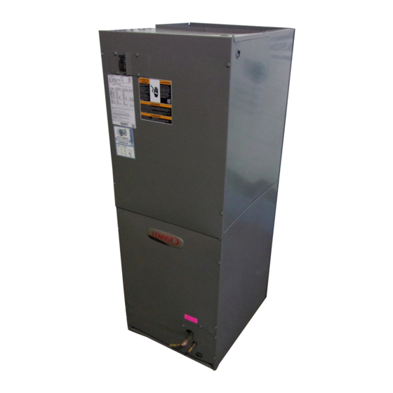
The CBX32MV is a high efficiency residential split system
blower/coil featuring a variable speed motor controlled by an
electronic blower drive control (BDC).
CBX32MV series units are designed to be matched with
Lennox two-speed or single-speed HFC−410A condensing
units and heat pumps. Several models are available in sizes
ranging from 1.5 through 5 tons. All units are equipped with
factory installed check and expansion valve for cooling or heat
pump applications.
Electric heat is available in several voltages and KW sizes,
and can be field installed in the cabinet.
Some CBX32MV applications may include the optional
®
Lennox
ComfortSense
Efficiency Plus Comfort Management Control (CCB1). The
purpose of both controls is to vary indoor blower speed in
response to indoor dehumidification demand. When a
two-speed outdoor unit is used, compressor speed can
also be controlled by the SignatureStat or CCB1 in
response to indoor dehumidification demand.
Information contained in this manual is intended for use by
experienced HVAC service technicians only.
specifications are subject to change. Procedures outlined
in this manual are presented as a recommendation only
and do not supersede or replace local or state codes.
CBX32MV (HFC−410A) SERIES UNITS
. . . . . . . . . . . . . . . . . . .
. . . . . . . . . . . . . . . . . .
. . . . .
. . . . . . . . . . . . . . . . . . . . . . .
. . . . . . . . . . . . . . . . . . . .
. . . . . . . . . . . . . . . . . .
. . . . . . . . . . . . . . . . . .
. . . . . . . . . . . . . .
7000,
SignatureStatt
Corp. 0206−L3
Revised 02−2010
1
2
2
4
10
11
11
15
17
23
30
34
35
35
36
ELECTROSTATIC DISCHARGE (ESD)
Precautions and Procedures
or
Electrostatic discharge can affect electronic
components. Take precautions during unit instal-
lation and service to protect the unit's electronic
controls. Precautions will help to avoid control
exposure to electrostatic discharge by putting
the unit, the control and the technician at the
same electrostatic potential. Neutralize electro-
All
static charge by touching hand and all tools on an
unpainted unit surface before performing any
service procedure.
Page 1
CBX32MV
WARNING
Electric shock hazard. Can cause injury
or death. Before attempting to perform
any service or maintenance, turn the
electrical power to unit OFF at discon-
nect switch(es). Unit may have multiple
power supplies.
CAUTION
2002 Lennox Industries Inc.
Advertisement
Table of Contents

Related Manuals for Lennox CBX32MV Series


Summary of Contents for Lennox CBX32MV Series
-
Page 1: Table Of Contents
(BDC). Electric shock hazard. Can cause injury CBX32MV series units are designed to be matched with or death. Before attempting to perform Lennox two-speed or single-speed HFC−410A condensing any service or maintenance, turn the units and heat pumps. -
Page 2: Model Number Identification
Model Number Identification − − − − Minor Revision Number Unit Type CB = Air Handler Refrigerant Metering Device Refrigerant Type 2 = Fixed Orifice X = R−410A 3 = TXV − Bleedport (indoor unit) 4 = TXV − Non−bleedport (indoor unit) Series 5 = TXV −... - Page 3 Specifications General Data Model Number CBX32MV-048 CBX32MV-060 CBX32MV-068 Nominal cooling capacity − tons (kW) 4 (14.1) 5 (17.6) 5+ (17.6+) Refrigerant R−410A R−410A R−410A 7/8 (22.2) 1-1/8 (28) 1-1/8 (28) Connections Suction (vapor) line − sweat in. (mm) 3/8 (9.5) 3/8 (9.5) 3/8 (9.5) Liquid line −...
- Page 4 COOL speed setting. Earlier production units continuous blower speed is approximately 50% of COOL speed setting. Harmony Zone Control applications − Low speed cooling is approximately 250 cfm (118 L/s). Lennox Harmony IIIt Zone Control applications − Low speed cooling is 300 cfm (145 L/s) CBX32MV-018/024 BLOWER MOTOR WATTS AT +" (Plus) BDC3 SETTING ( Adjust"...
- Page 5 CBX32MV-024/030 BLOWER PERFORMANCE 0 through 0.80 in. w.g. (0 through 200 Pa) External Static Pressure Range BDC3 Jumper Speed Positions HEAT" Speed COOL" Speed ADJUST" Jumper Setting 1070 1210 1100 1320 NORM 1100 1000 1200 − 1080 NOTES − The effect of static pressure, filter and electric heater resistance is included in the air volumes listed. Low speed cooling air volume is 70% of COOL speed setting.
- Page 6 Harmony Zone Control applications − Low speed cooling is approximately 380 cfm (178 L/s). Lennox Harmony IIIt Zone Control applications − minimum blower speed is 442 cfm (210 L/s). CBX32MV-036 BLOWER MOTOR WATTS AT +" (Plus) BDC3 SETTING ( Adjust"...
- Page 7 Harmony Zone Control applications − Low speed cooling is approximately 400 cfm (190 L/s). Lennox Harmony IIIt Zone Control applications − minimum blower speed is 442 cfm (210 L/s) CBX32MV-048 AND CBX32MV-060 BLOWER MOTOR WATTS AT +" (Plus) BDC3 SETTING ( Adjust"...
- Page 8 COOL speed setting. Earlier production units continuous blower speed is approximately 50% of COOL speed setting. Lennox Harmony IIIt Zone Control applications − minimum blower speed is 442 cfm (210 L/s). CBX32MV-068 BLOWER MOTOR WATTS AT +" (Plus) BDC3 SETTING ( Adjust" Jumper at +" Setting) Motor Watts @ Various External Static Pressures −...
-
Page 9: Parts Arrangement
Parts Arrangement ELECTRIC HEAT SECTION CBX32MV CONTROL BOX BLOWER COMPARTMENT BLOWER ACCESS PANEL HORIZONTAL DRAIN PAN COIL COIL ACCESS PANEL CHECK AND EXPANSION VALVE (COMPLETE WITH SCREEN) UPFLOW/DOWNFLOW DRAIN PAN FIGURE 1 CBX32MV CONTROL BOX LARGE ELECTRIC HEAT ADDITIONAL KNOCK TERMINAL SMALL ELECTRIC HEAT BLOWER... -
Page 10: I−Application
Y1 to Y2 G−Coil C−Transformer (T1) All CBX32MV series units use a single line voltage to All CBX32MV series units have dual slab coils arranged in 24VAC transformer mounted in the control box. The an "A" configuration. Each coil has two or three rows of transformer supplies power to the control circuits in the copper tubes fitted with ripple-edge aluminum fins. - Page 11 CBX32MV BLOWER MOTOR running. SHAFT Table 2 shows the recommended factory blower speed tap selections for CBX32MV series units. These settings are for nominal tonnage match−ups with the CBX32MV. When matched with other sizes, it is recommended that the CFM MOTOR be adjusted to approximately 400 CFM per ton.
-
Page 12: Adjust" 1
12 and 13 for various scenarios concerning use of EfficiencyPlus CCB1 humidity control will provide 70% of the SignatureStat and the CBX32MV series unit. the COOL CFM during first−stage cooling for two−speed outdoor units. Units built prior to August 2002, will provide either 60% (−048, −060 series units) or 65% (−036 series... -
Page 13: Jumper
CBX32MV units built prior to February 2003 #1 PIN JUMPERED 100% CFM A−Motor runs at 100% until demand is satisfied. 100% CFM (*45 seconds) B− Once demand is met, motor ramps down to off. COOLING DEMAND * CB32XMV units date coded prior to 2−2006 will delay 60 seconds 100% CFM #3 Pins Jumpered COOLING... - Page 14 70% of COOL speed for ALL model units. Reduced blower Kit #70J11 can be used to check the motor. The kit is available at the Lennox parts center. If not using the kit, speed for production prior to August 2002 is 65% of COOL for follow the procedure below.
-
Page 15: Optional Electric Heat
IV−OPTIONAL ECB29/31 ELECTRIC HEAT contacts to close. When the relay is de-energized, the disk cools and the contacts open. The relays energize different stages of heat, as well as the A−Matchups and Ratings blower. The blower is always first on and last off. Tables 4, 5 and 6 show all approved CBX32MV to ECB29 3−Circuit Breaker (CB1, CB2, and CB3) matchups and electrical ratings. - Page 16 TABLE 4 − ELECTRIC HEAT DATA SINGLE PHASE ELECTRIC HEAT CBX32MV−018/024 CBX32MV−024/030 Minimum Maximum Blower Blower Circuit Overcurrent Motor Minimum Maximum Motor No. of Volts Btuh Ampacity Protection Full Circuit Overcurrent Full Steps Input Input Input Load Ampacity Protection Load Circuit Circuit Amps...
- Page 17 TABLE 5 − ELECTRIC HEAT DATA SINGLE PHASE ELECTRIC HEAT CBX32MV−036 Minimum Maximum Circuit Overcurrent Protection Blower Volts Btuh Ampacity Motor Full Input Input Input Steps Load Amps Circuit Circuit Model Number 5 kW ECB29-5 (28K31) 12,800 − − − −...
- Page 18 TABLE 6 − ELECTRIC HEAT DATA SINGLE PHASE ELECTRIC HEAT CBX32MV−048, CBX32MV−060 and CBX32MV−068 Minimum Maximum Blower Circuit Ampacity Overcurrent Protection Volts Btuh Motor Input Input Input Full Load Circuit Circuit Circuit Circuit Circuit Circuit Steps Amps Model Number 12,800 −...
- Page 19 ECB29-5, -5CB 208/230 SINGLE−PHASE ELECTRIC HEAT VESTIBULE PARTS ARRANGEMENT ELECTRIC HEAT VESTIBULE PANEL ELECTRIC HEAT ELEMENT (HE1) PRIMARY LIMIT (S15) & SECONDARY LIMIT (S20) TERMINAL BLOCK (TB2) ELECTRIC HEAT SEQUENCER RELAY (K32) CIRCUIT BREAKER (CB1) FIGURE 7 ECB29-8 AND -8CB 208/230 SINGLE−PHASE ELECTRIC HEAT VESTIBULE PARTS ARRANGEMENT ECB29−8 CIRCUIT ELECTRIC HEAT...
- Page 20 ECB29-8,−10 208/230 THREE−PHASE ECB29-12.5CB, -15CB 208/230 SINGLE & THREE−PHASE ELECTRIC HEAT VESTIBULE PARTS ARRANGEMENT ELECTRIC HEAT ELEMENT (HE3) ELECTRIC HEAT ELECTRIC HEAT ELEMENT (HE2) ELECTRIC HEAT SEQUENCER RELAY (K33) VESTIBULE PANEL CIRCUIT BREAKER (CB1) ELECTRIC HEAT ELEMENT (HE1) PRIMARY LIMIT (S15) &...
-
Page 21: Optional Humidity Control
V− OPTIONAL HUMIDITY CONTROL (A20) When the CCB1 senses that the indoor humidity level is above the control setpoint, the control places the CBX32MV and outdoor unit in a dehumidification mode . To produce drier air, the CBX32MV will slow down the EfficiencyPlus PARTS IDENTIFICATION speed of the air crossing the indoor coil. -
Page 22: Adjust" 1
This can create a constant See tables 10 and 11 for various scenarios concerning use demand for humidity removal and may cause extended of the CCB1 humidity control and the CBX32MV series unit. compressor run times. Refer to table 7 for jumpers per ®... -
Page 23: Jumper
NOTE−The indoor blower speed is reduced in order to Basic Mode: Dehumidification only with a cooling demand. COOL is on, then D is active (reverse logic, off), and G is on slow the air speed across the indoor coil. The supply air (if not already on), Y1 and Y2 (if available) is on. - Page 24 Setting Dehumidity Levels Setting Dehumidity Levels HUMIDIFY MENU DEHUMIDIFY MENU MODE MODE DEHUMIDIFY DEHUMIDIFY MAIN MENU MAIN MENU SELECT SELECT FIGURE 15 Figure 16 Dehumidity Sensor Settings 2 − Use the up and down button to adjust the humidity level. The dehumidity sensor settings have minimum and See figure 17.
-
Page 25: Speed
TABLE 10 TYPICAL CBX32MV, CCB1 and TWO−SPEED OUTDOOR UNIT OPERATING SEQUENCE OPERATING SEQUENCE SYSTEM DEMAND SYSTEM RESPONSE *Relative Humidity Thermostat Blower CFM System Compres- Comments Step (EfficiencyPlus Demand (COOL) Condition sor Speed Lights) Acceptable (None) 40% of COOL Compressor demand and indoor blower Normal operation speed follow thermostat demand. - Page 26 TABLE 11 TYPICAL CBX32MV, CCB1 and SINGLE SPEED OUTDOOR UNIT OPERATING SEQUENCE OPERATING SEQUENCE SYSTEM DEMAND SYSTEM RESPONSE Thermostat Relative Humidity Blower CFM System Comments Step Demand (EfficiencyPlus Lights) (COOL) Condition Compressor demand and indoor blower Normal operation Acceptable (None) COOL speed follow thermostat demand.
- Page 27 TABLE 13 CBX32MV, SignatureStat or ComfortSense 7000 and TWO STAGE OUTDOOR UNIT OPERATING SYSTEM DEMAND SYSTEM RESPONSE SEQUENCE Thermostat Demand Relative Humidity Blower System Step Compressor Comments Condition Status (COOL) NO CALL FOR DEHUMIDIFICATION Normal Operation − Acceptable Compressor and indoor blower follow thermostat Normal Operation −...
-
Page 28: Configuration Modifications
VI−CONFIGURATION MODIFICATIONS UPFLOW CONFIGURATION CBX32MV unit may be installed in the upflow, downflow, horizontal right-hand discharge or horizontal left-hand discharge orientation. The units come from the factory ready for upflow or horizontal right-hand discharge installation. If the unit needs to be modified from its original configuration, use the HORIZONTAL following procedures. - Page 29 DOWNFLOW DISCHARGE CONFIGURATION DOWNFLOW DRIP SHIELDS HORIZONTAL DRAIN PAN* Coil Drip Shield UPFLOW/ *FOR OPTIMUM DOWNFLOW PERFORMANCE, DRAIN PAN REMOVE HORIZONTAL DRAIN PAN. Drip Pan FIGURE 19 FIGURE 21 6− Replace coil assembly and blower if removed. Replace coil access panel. If horizontal drain pan is not 4−...
- Page 30 NOTE−For horizontal applications in high humidity DOWNFLOW COMBUSTIBLE BASE DIMENSIONS areas, remove the downflow rail closest to the drain pan. 1-5/8 TOP VIEW (41) Removal of downflow rail will prevent sweating in high 1-5/8 humidity areas. To remove rail, remove screw from rail at 11-3/8 (41) (289)
- Page 31 E−Horizontal Left−Hand Discharge Application NOTE−For horizontal applications above the ceiling, a TOP CAP secondary drain pan is recommended. Refer to local codes. 1− Remove access panels and horizontal drip shield (−068 BACK COIL END model) from the corrugated padding between the SEAL blower and coil assembly.
-
Page 32: Start Up Operation
12− Set unit so it is sloped toward the drain pan (1/4" 4− Horizontal runs must be sloped 1" (25mm) per 10 feet [6mm]). Connect return and supply air plenums as (3.1m) of drain line to offset friction. required using sheet metal screws. 5−... -
Page 33: Operating Characteristics
VIII−TYPICAL OPERATING CHARACTERISTICS IX−MAINTENANCE A−Blower Operation and Adjustment WARNING NOTE− The following is a generalized procedure and does not apply to all thermostat controls. Electric shock hazard. Can cause injury or death. Before attempting to perform 1− Blower operation is dependent on thermostat any service or maintenance, turn the control system. - Page 34 X−WIRING SCHEMATIC AND OPERATION SEQUENCE A−CBX32MV − 208/230V SINGLE PHASE − SEQUENCE OF OPERATION 1. Line voltage is routed to transformer T1 and blower 4. Blower motor B3 is energized on heating speed after motor B3. K20−1 closes (see electric heat). 2.
- Page 35 TABLE 16 CBX32MV COOLING OPERATION AND JUMPER SUMMARY (OPTIONAL ACCESSORIES) WITHOUT SignatureStat OR CCB1 WITHOUT HARMONY THERMOSTAT UNIT JUMPERS BLOWER SPEED DEMAND DS to Y1 Single Speed Y1 to Y2 COOL Condensing Unit O to R *60%/65%/70% of COOL Two Speed DS to Y1 Condensing Unit O to R...
- Page 36 B−ECB29-5, -5CB, -8, -8CB − 208/230V SINGLE PHASE − SEQUENCE OF OPERATION 1. When there is a call for heat, W1 of the thermostat 3. Assuming the N.C. primary (S15) and secondary (S20) energizes the electric heat relay K32 with 24VAC. limit switches are closed, electric heat element HE1 is energized.
- Page 37 D−ECB29-12.5CB, -15CB − 208/230V SINGLE PHASE − SEQUENCE OF OPERATION FIRST−STAGE HEAT SECOND−STAGE HEAT (remove jumper between W2 and R) 1. When there is a call for heat, W1 of the thermostat 4. When K32-2 closes, the unit is ready for a second stage energizes the electric heat relay K32 with 24VAC.
- Page 38 F−ECB29-25CB − 208/230V SINGLE PHASE − SEQUENCE OF OPERATION FIRST−STAGE HEAT 5. When K33-1 closes, the blower (if not energized) is energized on heating speed and economizer heat relay 1. When there is a call for heat, W1 of the thermostat K43 is energized (see 208/230VAC CB schematic).
- Page 39 G−ECB29-8, -10,−15CB − 208/230V THREE PHASE − SEQUENCE OF OPERATION 1. When there is a call for heat, W1 of the thermostat energized (see unit schematic figure 26). energizes the electric heat relays K32 and K33 with 3. When K32-1, K32-2, and K33-2 closes, assuming the 24VAC.
- Page 40 H−ECB29-20CB, -25CB − 208/230V THREE PHASE − SEQUENCE OF OPERATION FIRST−STAGE HEAT SECOND−STAGE HEAT (remove jumper between W2 and R) 1. When there is a call for heat, W1 of the thermostat energizes the electric heat relays K32 and K34 with 5.