Agilent Technologies 1290 Infinity User Manual
Binary pump
Hide thumbs
Also See for 1290 Infinity:
- User manual (302 pages) ,
- Technical note (100 pages) ,
- Manual (16 pages)
Table of Contents
Advertisement
Quick Links
Advertisement
Chapters
Table of Contents

Related Manuals for Agilent Technologies 1290 Infinity


Summary of Contents for Agilent Technologies 1290 Infinity
- Page 1 Agilent 1290 Infinity Binary Pump User Manual Agilent Technologies...
- Page 2 (June 1987) or any equivalent agency regu- lation or contract clause. Use, duplication or disclosure of Software is subject to Agi- lent Technologies’ standard commercial license terms, and non-DOD Departments and Agencies of the U.S. Government will Agilent 1290 Infinity Binary Pump User Manual...
- Page 3 3 Installing the Module This chapter gives information about the preferred stack setup for your system and the installation of your Agilent 1290 Infinity Binary Pump. 4 Using the Pump This chapter explains the operational parameters of the Agilent 1290 Infinity Binary Pump.
- Page 4 8 Test Functions and Calibrations This chapter describes the tests for the module. 9 Maintenance This chapter describes the maintenance of the Agilent 1290 Infinity Binary Pump. 10 Parts and Materials for Maintenance This chapter provides information on parts for maintenance.
-
Page 5: Table Of Contents
Algae Growth in HPLC Systems Setting up the Pump with the Instrument Control Interface Purging the Pump Solvent Information Solvent Recommendation for Agilent 1290 Infinity and 1290 Infinity II and 1260 Infinity II Flexible Pumps Agilent 1290 Infinity Binary Pump User Manual... - Page 6 Replacing the Solvent Selection Valve (SSV) Changing configuration or replacing the Jet Weaver Replacing the Seal Wash Pump Releasing a Stuck Inlet Valve Remove the Pump Head Assembly Pump Head Maintenance (Tool Free) Agilent 1290 Infinity Binary Pump User Manual...
- Page 7 Cover Parts Leak Parts Fuses Accessory Kit Tools HPLC System Tool Kit 11 Identifying Cables Cable Overview Analog cables Remote Cables BCD Cables CAN/LAN Cable RS-232 Cable Kit Agilent 1200 Module to Printer Agilent 1290 Infinity Binary Pump User Manual...
- Page 8 Link configuration selection Manual Configuration PC and User Interface Software Setup Setup 14 Appendix General Safety Information The Waste Electrical and Electronic Equipment (WEEE) Directive (2002-96-EC) Radio Interference Sound Emission Agilent Technologies on Internet Agilent 1290 Infinity Binary Pump User Manual...
- Page 9 Agilent 1290 Infinity Binary Pump User Manual Introduction Features Overview of the Binary Pump Pump Principle System Overview Leak and Waste Handling This chapter gives an introduction to the pump, instrument overview and internal connectors. Agilent Technologies...
-
Page 10: Introduction Features
• High resolution piston movement control for smooth and reliable motion. For specifications, see Table 2 on page 22. This Binary pump has been introduced together with the Agilent 1290 Infinity Liquid N O T E Chromatograph. Agilent 1290 Infinity Binary Pump User Manual... -
Page 11: Overview Of The Binary Pump
Overview of the Binary Pump Overview of the Binary Pump The Agilent 1290 Infinity Binary Pump comprises two identical pumps integrated into one housing. Binary gradients are created by high-pressure mixing. A degassing unit is included for applications that require best flow stability, especially at low flow rates, for maximum detector sensitivity. -
Page 12: Pump Principle
A system pressure sensor, for monitoring the pump pressure, is attached to the purge valve, normally connected in the B-channel of the pump, before the mixing groove, in order to minimize delay volumes. Agilent 1290 Infinity Binary Pump User Manual... - Page 13 Introduction Pump Principle Figure 1 The hydraulic path Agilent 1290 Infinity Binary Pump User Manual...
- Page 14 In order to be able to control these movements a high resolution encoder unit is attached to the pump drives which resolves a revolution into 65000 steps, and each step translates to a volume of about 300 pl. Agilent 1290 Infinity Binary Pump User Manual...
-
Page 15: System Overview
The 1200 Infinity Series has been designed for safe leak and waste handling. It is important that all security concepts are understood and instructions are carefully followed. Figure 2 Leak and waste handling concept (overview - typical stack configuration as an example) Agilent 1290 Infinity Binary Pump User Manual... - Page 16 The waste tube of the purge valve (6) guides solvents to waste. The waste tube connected to the leak pan outlet on each of the bottom instruments (7) guides the solvent to a suitable waste container. Agilent 1290 Infinity Binary Pump User Manual...
-
Page 17: Site Requirements And Specifications
Agilent 1290 Infinity Binary Pump User Manual Site Requirements and Specifications Site Requirements Physical Specifications Specifications This chapter provides information on environmental requirements, physical and performance specifications. Agilent Technologies... -
Page 18: Site Requirements
➔ Make sure the power connector of the instrument can be easily reached and unplugged. ➔ Provide sufficient space behind the power socket of the instrument to unplug the cable. Agilent 1290 Infinity Binary Pump User Manual... - Page 19 Never use the power cords that Agilent Technologies supplies with this instrument for any other equipment. ➔ Never use cables other than the ones supplied by Agilent Technologies to ensure proper functionality and compliance with safety or EMC regulations. Absence of ground connection WA R N I N G The absence of ground connection can lead to electric shock or short circuit.
- Page 20 ➔ If your module was shipped in cold weather, leave it in its box and allow it to warm slowly to room temperature to avoid condensation. Agilent 1290 Infinity Binary Pump User Manual...
-
Page 21: Physical Specifications
Up to 2000 m (6562 ft) Non-operating altitude Up to 4600 m (15092 ft) For storing the module Safety standards: Installation category II, Pollution degree 2 For indoor use only. IEC, CSA, UL Agilent 1290 Infinity Binary Pump User Manual... -
Page 22: Specifications
Delay volume is then solely determined by the volume of the connection capillary. Composition range Settable range: 0 – 100 % Recommended range: 1 – 99 % or 5 µl/min per channel, whatever is greater. Agilent 1290 Infinity Binary Pump User Manual... - Page 23 Electronic records of maintenance and errors. Housing All materials recyclable. Agilent 1290 Infinity Binary Pump User Manual...
- Page 24 Site Requirements and Specifications Specifications Agilent 1290 Infinity Binary Pump User Manual...
-
Page 25: Installing The Module
Removing the Transport Foam Installing the Pump Flow Connections to the Pump Installation of Seal Wash Function This chapter gives information about the preferred stack setup for your system and the installation of your Agilent 1290 Infinity Binary Pump. Agilent Technologies... -
Page 26: Unpacking The Module
Unpacking the Module Damaged Packaging If the delivery packaging shows signs of external damage, please call your Agilent Technologies sales and service office immediately. Inform your service representative that the instrument may have been damaged during shipment. "Defective on arrival" problems C AU T I O N If there are signs of damage, please do not attempt to install the module. -
Page 27: Optimizing The Stack Configuration
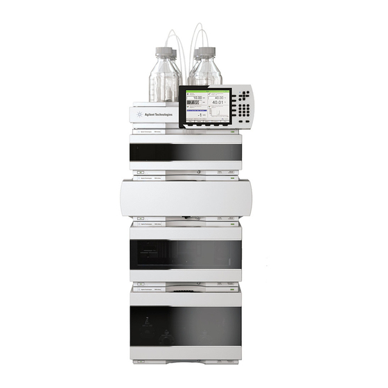
Installing the Module Optimizing the Stack Configuration Optimizing the Stack Configuration If your module is part of a complete Agilent 1290 Infinity Liquid Chromatograph, you can ensure optimum performance by installing the following configurations. These configurations optimize the system flow path, ensuring minimum delay volume. - Page 28 Installing the Module Optimizing the Stack Configuration Figure 3 Recommended stack configuration for 1290 Infinity (front view) Agilent 1290 Infinity Binary Pump User Manual...
- Page 29 Installing the Module Optimizing the Stack Configuration Figure 4 Recommended stack configuration 1290 Infinity (rear view) Agilent 1290 Infinity Binary Pump User Manual...
-
Page 30: Two Stack Configuration
A slightly longer capillary is required between the pump and autosampler. (See Figure 5 on page 30 and Figure 6 on page 31). Figure 5 Recommended two stack configuration for 1290 Infinity (front view) Agilent 1290 Infinity Binary Pump User Manual... - Page 31 Installing the Module Optimizing the Stack Configuration Figure 6 Recommended two stack configuration for 1290 Infinity (rear view) Agilent 1290 Infinity Binary Pump User Manual...
-
Page 32: Installation Information On Leak And Waste Handling
A printed copy of the guideline has been shipped with the solvent cabinet, electronic copies are available on the Internet. Recommendations for Solvent Cabinet N O T E For details, see the usage guideline for the Agilent 1200 Infinity Series Solvent Cabinets. Agilent 1290 Infinity Binary Pump User Manual... - Page 33 Leak pan's outlet port (A), leak funnel (B) and corrugated waste tube (C) Waste tube of the sampler’s needle wash Condense drain outlet of the autosampler cooler Waste tube of the purge valve Waste tube Agilent 1290 Infinity Binary Pump User Manual...
- Page 34 Do not bend tubes. ➔ Do not immerse tube end in waste liquid. ➔ Do not intubate tubes in other tubes. ➔ For correct tubing follow instructions on label attached to the module. Agilent 1290 Infinity Binary Pump User Manual...
- Page 35 Installing the Module Installation Information on Leak and Waste Handling Figure 8 Warning label (illustration for correct waste tubing) Agilent 1290 Infinity Binary Pump User Manual...
-
Page 36: Removing The Transport Foam
Installing the Module Removing the Transport Foam Removing the Transport Foam Open the front cover of the module. Carfully remove the protective foam. Close the front cover. Agilent 1290 Infinity Binary Pump User Manual... -
Page 37: Installing The Pump
Parts required Description Pump Power cord Agilent Control Software and/or Instant Pilot G4208 Preparations Locate bench space Provide power connections Unpack the pump 1 Place the module on the bench in a horizontal position. Agilent 1290 Infinity Binary Pump User Manual... - Page 38 2 Ensure the power switch on the front of the module is OFF (switch stands out). Figure 9 Front of Binary Pump 3 Connect the power cable to the power connector at the back of the 1290 Infinity Binary Pump. Agilent 1290 Infinity Binary Pump User Manual...
- Page 39 Installing the Module Installing the Pump 4 Connect the required interface cables to the rear of the 1290 Infinity Binary Pump. Figure 10 Rear of Binary Pump In an Agilent 1290 Infinity System, the individual modules are connected by CAN cables.
- Page 40 When the line power button stands out and the green light is off, the module is turned off. N O T E The module was shipped with default configuration settings. For changing these settings, N O T E refer to section Setting the 8-bit configuration switch. Agilent 1290 Infinity Binary Pump User Manual...
-
Page 41: Flow Connections To The Pump
The pump is shipped with tubing and capillary connections installed between solvent selection valve, degassing unit, pump heads, pressure sensor, purge valve, Jet Weaver, and seal wash pump. This section describes the installation of additional flow connections. Agilent 1290 Infinity Binary Pump User Manual... - Page 42 The volume of substances should be reduced to the minimum required for the analysis. ➔ Do not operate the instrument in an explosive atmosphere. 1 Remove the front cover by pressing the snap fasteners on both sides. Figure 11 Removing the Front Cover Agilent 1290 Infinity Binary Pump User Manual...
- Page 43 Infinity Binary Pump. 3 Put the four bottles into the solvent cabinet and screw a bottle head assembly onto each bottle. 4 Install the shutoff valve panel at the top left corner of the instrument. Agilent 1290 Infinity Binary Pump User Manual...
- Page 44 (usually channel A1). 6 Label the tubes accordingly using the supplied stickers and fix the tubes in the clips of solvent cabinet and 1290 Infinity Binary Pump. 7 Connect the outlet of the Jet Weaver to the autosampler.
-
Page 45: Installation Of Seal Wash Function
Figure 12 Binary Pump with Seal Wash Function The 1290 Infinity Binary Pump has a built-in seal wash function, which is recommended when using buffers or other non-volatile solvents or additives that could deposit on pistons and seals. It is used for regularly cleaning these parts automatically. - Page 46 Installing the Module Installation of Seal Wash Function Agilent 1290 Infinity Binary Pump User Manual...
-
Page 47: Using The Pump
Control Settings Method Parameter Settings Purging the Pump Solvent Information Solvent Recommendation for Agilent 1290 Infinity and 1290 Infinity II and 1260 Infinity II Flexible Pumps Normal Phase Applications Solvent Handling This chapter explains the operational parameters of the Agilent 1290 Infinity Binary Pump. -
Page 48: Magnets
Using the Pump Magnets Magnets This stack exemplarily shows the magnets' positions in the modules. Agilent 1290 Infinity Binary Pump User Manual... -
Page 49: Turn On/Off
Using the Pump Turn on/off Turn on/off Power switch: On Turn instrument On/Off with the control software. Power switch: Off Agilent 1290 Infinity Binary Pump User Manual... - Page 50 Using the Pump Turn on/off Agilent 1290 Infinity Binary Pump User Manual...
-
Page 51: Status Indicators
5. Resident mode (blinking) - for example during update of main firmware. 6. Bootloader mode (fast blinking). Try to re-boot the module or try a cold-start. Then try a firmware update. Agilent 1290 Infinity Binary Pump User Manual... -
Page 52: Leak And Waste Handling
N O T E For details, see the usage guideline for the Agilent 1200 Infinity Series Solvent Cabinets. For details on correct installation, see section Installation Information on Leak and Waste Handling in the service manual. Agilent 1290 Infinity Binary Pump User Manual... -
Page 53: Best Practices
• Purge each channel with fresh solvent at 2.5 – 3 mL/min for 5 min. • Equilibrate your system with composition of your application for 15 min. Use conditioning for 1290 Infinity II Pumps and G7104C. Weekly tasks • Change seal wash solvent (10 % / 90 % isopropanol/water) and bottle. -
Page 54: Power Up / Shut-Down The Pump
• Equilibrate your system with composition of your application for 15 min. Use conditioning for 1290 Infinity II Pumps and G7104C. Long-term shut-down of the system • Flush system with water to remove buffer. - Page 55 The seal wash function regularly cleans these parts automatically. Seal Wash Dialog in OpenLAB Software (1290 Infinity Pumps only): • Seal Wash settings are NO method parameters • Find dialog under Control •...
-
Page 56: How To Deal With Solvents
Assembly (5067-5407)) with a nominal filter pore size of 0.3 μL. Advantages of the inline filter: • Very small internal volume • Specified for working at high pressures • Possibility of back-flushing the filter Agilent 1290 Infinity Binary Pump User Manual... - Page 57 • exchange the filter frit on a regular basis. Damage to the valve C AU T I O N ➔ Use the filter flush mode only if the optional inline filter is installed. See Technote G7167-90130 for further reference. Agilent 1290 Infinity Binary Pump User Manual...
-
Page 58: Preparing The Binary Pump
0.1 M or higher are being pumped for long periods of time. • Never leave an unused pump with water in a channel for an extended period of time (2-3 days). Always flush with organic solvent or add 10 % isopropanol to water. Agilent 1290 Infinity Binary Pump User Manual... -
Page 59: Algae Growth In Hplc Systems
• Use the amber solvent bottle ( Solvent bottle, amber, 1000 mL (9301-6526)) supplied with the instrument for your aqueous mobile phase. • If possible add a few mg/L sodium azide or a few percent organic solvent to the aqueous mobile phase. Agilent 1290 Infinity Binary Pump User Manual... -
Page 60: Setting Up The Pump With The Instrument Control Interface
The Binary Pump configuration parameters are in two sections: • Communication • Options Communication: The parameters in this dialog box are detected automatically during autoconfiguration. • Device name, • Type ID, • Serial number, • Firmware revision, • Button Connection settings Agilent 1290 Infinity Binary Pump User Manual... - Page 61 Configure Solvent Type Catalogs: Displays the Solvent Type Catalogs dialog box, which allows you to import and export solvent calibration data. See “Importing Solvent Calibration Tables” on page 90. Please refer to the online help of your user interface for more detailed information. Agilent 1290 Infinity Binary Pump User Manual...
-
Page 62: The Pump User Interface (Dashboard Panel)
The pressure setpoints. The red line shows the current maximum pressure limit; the green area shows the current pressure (also shown as text). The current solvent flow rate (in mL/min) is displayed above the pressure display. Agilent 1290 Infinity Binary Pump User Manual... - Page 63 Displays the Bottle Fillings dialog box. Prepare Pump Allows you to control the Purge, Condition or the Prime function. Seal Wash Purge Allows you to refill the Seal Wash lines once the Seal Wash solvent has been changed Agilent 1290 Infinity Binary Pump User Manual...
-
Page 64: Control Settings
Conditioning may be necessary if the pump may contain air, for example after running out of solvent, after a long period of standby or after service or repair. Agilent 1290 Infinity Binary Pump User Manual... -
Page 65: Method Parameter Settings
Your instrument remains in a not ready state during the posttime to delay Off (0.0 min ). the start of the next analysis. You can use the Posttime to allow your column to equilibrate after changes in solvent composition (for example after gradient elution). Agilent 1290 Infinity Binary Pump User Manual... - Page 66 The External Contacts section enables you to set up the switching of the external contacts. N O T E The External Contacts section is present only when a BCD/external contacts board is installed. Agilent 1290 Infinity Binary Pump User Manual...
- Page 67 You can set a limit on the rate of change of the solvent flow to protect your Gradient 1000.000 mL/min/min analytical column. You can set individual values for Flow ramp up and Flow in steps of ramp down. 0.001 mL/min/min Default value: 100.000 mL/min/min Agilent 1290 Infinity Binary Pump User Manual...
- Page 68 • Change Solvent Composition - You can only use solvents, which have been enabled in the solvents section. • Function centric view - This checkbox allows you displaying parameter changes instead of a time table. Agilent 1290 Infinity Binary Pump User Manual...
-
Page 69: Purging The Pump
The pump should never be used for priming/purging empty tubings (never let the pump N O T E run dry). Use a syringe to draw enough solvent for completely filling the tubings to the pump inlet before continuing to prime with the pump. Agilent 1290 Infinity Binary Pump User Manual... - Page 70 6 Observe the pressure fluctuations. The system is air free as soon as the pressure is stable. 7 Change solvents and column according to the analytical conditions and purge the system to change solvents. Agilent 1290 Infinity Binary Pump User Manual...
-
Page 71: Solvent Information
• Avoid or minimize the use of solvents that may corrode parts in the flow path. Consider specifications for the pH range given for different materials like flow cells, valve materials etc. and recommendations in subsequent sections. Agilent 1290 Infinity Binary Pump User Manual... - Page 72 Piston/wash seals UHMW-PE, SST Pressure sensor Automatic purge valve Polyimide, SST, DLC Ultra clean tubings are available for the use with high-end MS detectors. They are also compatible to THF. Jet Weaver, Heat Exchanger Agilent 1290 Infinity Binary Pump User Manual...
- Page 73 (cresols, salicylic acid etc.). When used above room temperature, PEEK is sensitive to bases and various organic solvents, which can cause it to swell. Under such conditions normal Agilent 1290 Infinity Binary Pump User Manual...
- Page 74 Polyethylene (PE) Agilent uses UHMW (ultra-high molecular weight)-PE/PTFE blends for yellow piston and wash seals, which are used in 1290 Infinity pumps, 1290 Infinity II pumps, the G7104C and for normal phase applications in 1260 Infinity pumps. Polyethylene has a good stability for most common inorganic solvents including acids and bases in a pH range of 1 to 12.5.
- Page 75 (about pH 0.1) at room temperature is about 13 μm/year. At room temperature, titanium is resistant to concentrations of about 5 % sulfuric acid (about pH 0.3). Addition of nitric acid to hydrochloric or sulfuric acids Agilent 1290 Infinity Binary Pump User Manual...
- Page 76 Zirconium Oxide is inert to almost all common acids, bases and solvents. There are no documented incompatibilities for HPLC applications. Platinum/Iridium Platinum/Iridium is inert to almost all common acids, bases and solvents. There are no documented incompatibilities for HPLC applications. Agilent 1290 Infinity Binary Pump User Manual...
- Page 77 Sapphire, Ruby and Al -based ceramics Sapphire, ruby and ceramics based on aluminum oxide Al are inert to almost all common acids, bases and solvents. There are no documented incompatibilities for HPLC applications. Agilent 1290 Infinity Binary Pump User Manual...
-
Page 78: Solvent Recommendation For Agilent 1290 Infinity And 1290 Infinity Ii And 1260 Infinity Ii Flexible Pumps
Using the Pump Solvent Recommendation for Agilent 1290 Infinity and 1290 Infinity II and 1260 Infinity II Flexible Pumps Solvent Recommendation for Agilent 1290 Infinity and 1290 Infinity II and 1260 Infinity II Flexible Pumps While the Agilent 1290 Infinity, 1290 Infinity II, and 1260 Infinity II Flexible Pumps guarantee a high performance with a wide variety of solvents, other solvents may cause harm to the pump or to the (U)HPLC system. -
Page 79: Normal Phase Applications
Using the Pump Solvent Recommendation for Agilent 1290 Infinity and 1290 Infinity II and 1260 Infinity II Flexible Pumps Normal Phase Applications Valves for Normal Phase Applications Current passive inlet valves and outlet ball valves used with Agilent Infinity and Infinity II pumps do not work well while running nonpolar solvents for normal phase applications (for example, hexane and heptane). -
Page 80: Solvent Handling
Using the Pump Solvent Recommendation for Agilent 1290 Infinity and 1290 Infinity II and 1260 Infinity II Flexible Pumps Table 7 Recommended valves for normal phase applications Binary or High Speed Pumps Quaternary or Flexible Pumps Inlet valves 1290 Infinity Inlet Valve Type N... - Page 81 Using the Pump Solvent Recommendation for Agilent 1290 Infinity and 1290 Infinity II and 1260 Infinity II Flexible Pumps Handling of Buffers The following recommendations should be observed when using buffer solutions: • Buffers and aqueous solutions are possible sources of algae contamination, for avoiding related problems, please read “Algae Growth in HPLC...
- Page 82 Using the Pump Solvent Recommendation for Agilent 1290 Infinity and 1290 Infinity II and 1260 Infinity II Flexible Pumps Handling of Acetonitrile Acetonitrile is a solvent that is frequently used in reversed-phase chromatography. Despite of its common use, it can be a source of issues if not handled correctly.
-
Page 83: Optimizing Performance
Agilent 1290 Infinity Binary Pump User Manual Optimizing Performance Delay Volume and Extra-Column Volume Delay Volume How to Configure the Optimum Delay Volume How to Achieve Higher Resolution Using Solvent Calibration Tables This chapter gives hints on how to optimize the performance or use additional devices. -
Page 84: Delay Volume And Extra-Column Volume
The delay volume in a system includes the volume in the pump from the point of mixing, connections between pump and autosampler, volume of the flow path through the autosampler and connections between autosampler and column. Agilent 1290 Infinity Binary Pump User Manual... -
Page 85: How To Configure The Optimum Delay Volume
(for example A versus B), that differ strongly in their UV/Vis absorption, for example by using trifluoroacetic acid (TFA) as a modifier, which has a high absorbance. Agilent 1290 Infinity Binary Pump User Manual... - Page 86 The 380 μL Jet Weaver strongly improves mixing and therefore reduces baseline noise and improves sensitivity in detection. Patented Agilent microfluidic technology offers high mixing performance at a low internal volume of 380 μL. Agilent 1290 Infinity Binary Pump User Manual...
-
Page 87: How To Achieve Higher Resolution
The resolution equation shows that the next most significant term is the plate count or efficiency, N, and this can be optimized in a number of ways. N is inversely proportional to the particle size and directly proportional to the Agilent 1290 Infinity Binary Pump User Manual... - Page 88 = time length of gradient (or segment of gradient) (min), • F = flow (ml/min), • V = column delay volume, • Δ%B = change in fraction of solvent B during the gradient, • S = constant (ca. 4-5 for small molecules). Agilent 1290 Infinity Binary Pump User Manual...
- Page 89 40 °C) can generate higher peak capacity than a longer STM column by virtue of running it faster. (Refer to Petersson et al., J.Sep.Sci, 31, 2346-2357, 2008, Maximizing peak capacity and separation speed in liquid chromatography). Agilent 1290 Infinity Binary Pump User Manual...
-
Page 90: Using Solvent Calibration Tables
5 Navigate to the location of the solvent calibration table and click Open. The new solvent will now appear in the Solvent Type Catalogs. The imported solvent is now available for selection as a solvent type in the pump's method parameters. Agilent 1290 Infinity Binary Pump User Manual... -
Page 91: Troubleshooting And Diagnostics
Agilent 1290 Infinity Binary Pump User Manual Troubleshooting and Diagnostics Available Tests vs User Interfaces Agilent Lab Advisor Software Overview about the troubleshooting and diagnostic features. Agilent Technologies... -
Page 92: Available Tests Vs User Interfaces
• Preferred tool should be the Agilent Lab Advisor software, see “Agilent Lab Advisor Software” on page 93. • The Agilent ChemStation may not include any maintenance/test functions. • Screenshots used within these procedures are based on the Agilent Lab Advisor software. Agilent 1290 Infinity Binary Pump User Manual... -
Page 93: Agilent Lab Advisor Software
The tests and diagnostic features that are provided by the Agilent Lab Advisor software may differ from the descriptions in this manual. For details, refer to the Agilent Lab Advisor software help files. Agilent 1290 Infinity Binary Pump User Manual... - Page 94 Troubleshooting and Diagnostics Agilent Lab Advisor Software Agilent 1290 Infinity Binary Pump User Manual...
-
Page 95: Error Information
Agilent 1290 Infinity Binary Pump User Manual Error Information What Are Error Messages General Error Messages Timeout Shutdown Remote Timeout Lost CAN Partner Leak Sensor Short Leak Sensor Open Compensation Sensor Open Compensation Sensor Short Fan Failed Leak Open Cover... - Page 96 Seal wash pump was missing when tried to turn on This chapter describes the meaning of error messages, and provides information on probable causes and suggested actions how to recover from error conditions. Agilent 1290 Infinity Binary Pump User Manual...
-
Page 97: What Are Error Messages
In all cases, error propagation is done via the CAN bus or via an APG/ERI remote cable (see documentation for the APG/ERI interface). Agilent 1290 Infinity Binary Pump User Manual... -
Page 98: General Error Messages
Check the logbook for the occurrence and A not-ready condition was present during a source of a not-ready condition. Restart the sequence or multiple-injection run for a analysis where required. period longer than the timeout threshold. Agilent 1290 Infinity Binary Pump User Manual... -
Page 99: Shutdown
Check the vacuum degasser for an error The degasser failed to generate sufficient condition. Refer to the Service Manual for the vacuum for solvent degassing. degasser or the pump that has the degasser built-in. Agilent 1290 Infinity Binary Pump User Manual... -
Page 100: Remote Timeout
Exchange the CAN cable. Defective CAN cable. Switch off the system. Restart the system, and Defective main board in another module. determine which module or modules are not recognized by the system. Agilent 1290 Infinity Binary Pump User Manual... -
Page 101: Leak Sensor Short
Leak sensor not connected to the main representative. board. Please contact your Agilent service Defective leak sensor. representative. Please contact your Agilent service Leak sensor incorrectly routed, being representative. pinched by a metal component. Agilent 1290 Infinity Binary Pump User Manual... -
Page 102: Compensation Sensor Open
Please contact your Agilent service Loose connection between the power representative. switch board and the main board Please contact your Agilent service Defective power switch assembly representative. Please contact your Agilent service Defective main board. representative. Agilent 1290 Infinity Binary Pump User Manual... -
Page 103: Compensation Sensor Short
Please contact your Agilent service Defective power switch assembly representative. Please contact your Agilent service Loose connection between the power representative. switch board and the main board Please contact your Agilent service Defective main board. representative. Agilent 1290 Infinity Binary Pump User Manual... -
Page 104: Fan Failed
Probable cause Suggested actions Please contact your Agilent service Fan cable disconnected. representative. Please contact your Agilent service Defective fan. representative. Please contact your Agilent service Defective main board. representative. Agilent 1290 Infinity Binary Pump User Manual... -
Page 105: Leak
Error ID: 0205 The top foam has been removed. Probable cause Suggested actions Please contact your Agilent service Foam not activating the sensor. representative. Please contact your Agilent service Defective sensor or main board. representative. Agilent 1290 Infinity Binary Pump User Manual... -
Page 106: Cover Violation
Probable cause Suggested actions Please contact your Agilent service The top foam was removed during representative. operation. Please contact your Agilent service Foam not activating the sensor. representative. Agilent 1290 Infinity Binary Pump User Manual... -
Page 107: Pump Error Messages
• Parameter: None Probable cause Suggested actions Check for leaks. Leak Check bottle filling. Bottle empty Check solvent. Wrong solvent (viscosity) Check flow rate and lower pressure limit. Inappropriate setting Replace column. Column degradation Agilent 1290 Infinity Binary Pump User Manual... -
Page 108: Target Pressure Not Reached For Binary Pump Degasser
Please contact your Agilent service Leak in degasser chamber or degasser representative. tubing. Please contact your Agilent service Defect vacuum pump. representative. Block unused degasser channels. Degasser chamber empty or connected to air. Agilent 1290 Infinity Binary Pump User Manual... -
Page 109: Solvent Counter Exceeded Limit
• Parameter: None Probable cause Suggested actions Empty waste container. The waste container is full. • Reset waste counter. Inappropriate setting for waste counter. • Adjust waste counter limit. Agilent 1290 Infinity Binary Pump User Manual... -
Page 110: Flow Rate Limit Exceeded
The binary pump has been shut down by the control software or control module during an analysis. • Parameter: 0 for off, 1 for standby. Probable cause Suggested actions Restart pump. Pump has been shut down. Agilent 1290 Infinity Binary Pump User Manual... -
Page 111: Reading The Pump Encoder Tag Failed
• Parameter: 1 – 4 referring to pump drive Probable cause Suggested actions Please contact your Agilent service Defect connection between encoder and representative. main board. Please contact your Agilent service Defect tag Defect connection between tag representative. and encoder. Agilent 1290 Infinity Binary Pump User Manual... -
Page 112: Pump Drive Blocked Or Encoder Failed
Please contact your Agilent service Wrong/missing connection of pump drive representative. to main board. Drive Encoder failed Error ID: 22408 Drive encoder failed during pump drive calibration. Probable cause Suggested actions Contact Agilent support. Internal error. Agilent 1290 Infinity Binary Pump User Manual... -
Page 113: Drive Current Too High
• Parameter: 1 – 4 referring to pump drive Probable cause Suggested actions Check for blockage of e.g. outlet valve filter frit, Blockage of system before pressure sensor. purge valve, heat exchanger. Please contact your Agilent service Drive motor defect. representative. Agilent 1290 Infinity Binary Pump User Manual... -
Page 114: Overcurrent Of Solvent Selection Valve (Ssv)
• Parameter: 1 – 4 referring to pump drive Probable cause Suggested actions Please contact your Agilent service Defect connection between main board and representative. pump drive encoder. Please contact your Agilent service Defect encoder. representative. Agilent 1290 Infinity Binary Pump User Manual... -
Page 115: Pump Drive Encoder Defect
Suggested actions Check cable connection. Reading of purge valve tag failed. Replace purge valve head. Purge valve head tag defect or empty. Please contact your Agilent service Purge valve tag reader is defect. representative. Agilent 1290 Infinity Binary Pump User Manual... -
Page 116: Pump Drive Encoder Rollover
Error ID: 22426 Insufficient power of drive encoder LED. • Parameter: 1 – 4 referring to pump drive Probable cause Suggested actions Please contact your Agilent service Pump drive encoder is defect. representative. Agilent 1290 Infinity Binary Pump User Manual... -
Page 117: Drive Encoder Error
Blockage of flow path between primary pump head and pressure sensor, e.g. of the • Please contact your Agilent service heat exchanger. representative. Please contact your Agilent service Primary pump drive is defect. representative. Agilent 1290 Infinity Binary Pump User Manual... -
Page 118: Current Of Secondary Pump Drive Too High
Error ID: 22437 The pump drive encoder has generated no signal. • Parameter: 1 – 4 referring to pump drive Probable cause Suggested actions Please contact your Agilent service Pump drive encoder is defect. representative. Agilent 1290 Infinity Binary Pump User Manual... -
Page 119: Pump Drive Error
Suggested actions Please contact your Agilent service Wiper shifted representative. Replace, clean or repair pump head. Pump head blocks piston movement Please contact your Agilent service Pump drive motor is mechanically blocked. representative. Agilent 1290 Infinity Binary Pump User Manual... -
Page 120: Pump Drive Stop Not Found
Error ID: 22443 Pressure sensor calibration wrong or missing. • Parameter: None Probable cause Suggested actions • Replace pressure sensor. Pressure sensor calibration wrong or missing. • Please contact your Agilent service representative. Agilent 1290 Infinity Binary Pump User Manual... -
Page 121: Seal Wash Pump Was Missing When Tried To Turn On
Probable cause Suggested actions Check cable connection. Defect cable connection to seal wash pump. Please contact your Agilent service Defect seal wash pump motor. representative. Please contact your Agilent service Defective main board. representative. Agilent 1290 Infinity Binary Pump User Manual... - Page 122 Error Information Pump Error Messages Agilent 1290 Infinity Binary Pump User Manual...
-
Page 123: Test Functions And Calibrations
Agilent 1290 Infinity Binary Pump User Manual Test Functions and Calibrations Introduction Pump Leak Rate Test Troubleshooting the Pump Leak Rate Test System Pressure Test This chapter describes the tests for the module. Agilent Technologies... -
Page 124: Introduction
• System pressure test • Monitoring of values • Pressure • Pressure ripple • Flow (in case of operating pressure) For details on the use of the interface refer to the interface documentation. Agilent 1290 Infinity Binary Pump User Manual... -
Page 125: Pump Leak Rate Test
• The allowed leak limit for the primary piston is ≤30 μL/min A report can be displayed, saved or printed by opening it with the Print Result button at the lower right of the screen. Agilent 1290 Infinity Binary Pump User Manual... - Page 126 If the test does not pass, check the system for leaks or call a local Agilent representative. Figure 14 on page 126 and Figure 15 on page 127 show a typical test run. Figure 14 Static (secondary) Leak Test Agilent 1290 Infinity Binary Pump User Manual...
- Page 127 Test Functions and Calibrations Pump Leak Rate Test Figure 15 Dynamic (primary) Leak Test Agilent 1290 Infinity Binary Pump User Manual...
- Page 128 • Leak in Inlet Valve • Check for moving air bubbles in tubing directly to the Inlet Valve • Purge the lines with water to remove dirt • Knock at the valve, clean or replace it Agilent 1290 Infinity Binary Pump User Manual...
- Page 129 Remove the SW tubes from the support ring and check for leaks • Replace the piston seals and clean the pistons • Ensure that seals are lubricated when pushed in • Use abrasive mesh >5000 grit Agilent 1290 Infinity Binary Pump User Manual...
-
Page 130: System Pressure Test
If the test does not pass, check the system for leaks or call a local Agilent representative. Figure 16 on page 131 shows a typical test run. Agilent 1290 Infinity Binary Pump User Manual... - Page 131 Test Functions and Calibrations System Pressure Test Figure 16 System Pressure Test Agilent 1290 Infinity Binary Pump User Manual...
- Page 132 Test Functions and Calibrations System Pressure Test Agilent 1290 Infinity Binary Pump User Manual...
-
Page 133: Maintenance
Agilent 1290 Infinity Binary Pump User Manual Maintenance Introduction to Maintenance Warnings and Cautions Overview of Maintenance Cleaning the Module Installing Fittings and Capillaries Replacing the Shutoff Valve Panel Replacing the Pressure Sensor Replacing the Inlet valve Replacing the Outlet Valve... - Page 134 Maintenance System Pressure Test Replacing Module Firmware Preparing the Pump Module for Transport This chapter describes the maintenance of the Agilent 1290 Infinity Binary Pump. Agilent 1290 Infinity Binary Pump User Manual...
-
Page 135: Introduction To Maintenance
Figure 17 on page 135 shows the main user accessible assemblies of the Agilent 1290 Infinity Binary Pump. These parts can be accessed from the front (simple repairs) and don’t require to remove the pump from the system stack. Figure 17... - Page 136 A “typical” application can be characterized as follows: • pressure range 100 – 800 bar, • flow rates 0.5 – 3.5 mL/min, • typical solvents used in reversed phase LC. Agilent 1290 Infinity Binary Pump User Manual...
-
Page 137: Warnings And Cautions
C AU T I O N ➔ If you connect external equipment to the instrument, make sure that you only use accessory units tested and approved according to the safety standards appropriate for the type of external equipment. Agilent 1290 Infinity Binary Pump User Manual... -
Page 138: Overview Of Maintenance
Maintenance Overview of Maintenance Overview of Maintenance The following pages describe maintenance (simple repairs) of the module that can be carried out without opening the main cover. Agilent 1290 Infinity Binary Pump User Manual... -
Page 139: Cleaning The Module
WA R N I N G hazard and damage the module ➔ Do not use an excessively damp cloth during cleaning. ➔ Drain all solvent lines before opening any connections in the flow path. Agilent 1290 Infinity Binary Pump User Manual... -
Page 140: Installing Fittings And Capillaries
The lifetime of a fitting depends on how firmly it has been tightened; firm tightening N O T E reduces the lifetime. If fitting has been overtightened, replace it. 1 Install fittings and capillaries. 2 Tighten fittings and capillaries. Agilent 1290 Infinity Binary Pump User Manual... -
Page 141: Replacing The Shutoff Valve Panel
Unscrew tubing connections between shutoff valves, If a single valve shall be replaced, it can be pulled to the solvent bottles and the solvent selection valve. front for removing it from its mounting Agilent 1290 Infinity Binary Pump User Manual... - Page 142 Maintenance Replacing the Shutoff Valve Panel Remove the shutoff valve panel by pulling it downwards After replacing the panel or after completion of other maintenance, re-install the panel and all flow connections. Agilent 1290 Infinity Binary Pump User Manual...
-
Page 143: Replacing The Pressure Sensor
Turn off pump flow, switch off pump This procedure describes how to replace the pressure sensor. N O T E In case the cable to the sensor shall be replaced as well, please contact your Agilent service representative. Agilent 1290 Infinity Binary Pump User Manual... - Page 144 Carefully pull out the pressure sensor for about 2 cm. Connect the new pressure sensor to the pressure sensor Then unscrew the cable from the pressure sensor. connector. Agilent 1290 Infinity Binary Pump User Manual...
- Page 145 Replacing the Pressure Sensor Fix the pressure sensor to the instrument chassis. Connect the capillaries from the valve to the pressure sensor: connect port 3 to the pressure sensor inlet and port 2 to the outlet. Agilent 1290 Infinity Binary Pump User Manual...
-
Page 146: Replacing The Inlet Valve
For best performance and life time and for avoiding leaks, use a torque wrench set to N O T E 10 Nm for fixing the inlet valve. Close the shut off valves to avoid solvent leaks. Unscrew the tubing at the inlet valve. Agilent 1290 Infinity Binary Pump User Manual... - Page 147 Install inlet valve and tighten it at 10 Nm with a torque remove it. wrench (14 mm). Attach the inlet tubing at the inlet valve. Open the shut off valves and purge the system to remove air. Agilent 1290 Infinity Binary Pump User Manual...
-
Page 148: Replacing The Outlet Valve
Outlet valve (primary pump head) G4220-20020 Internal gold seal for Outlet Valve Close the shut off valves to avoid solvent leaks. Lift up the capillary and remove it from the primary pump head. Agilent 1290 Infinity Binary Pump User Manual... - Page 149 10 Nm and close the outlet valve. outlet valve. Using a torque wrench with a 2.5 mm hex bit, set 3 Nm and close the hex screw at the top of the outlet. Agilent 1290 Infinity Binary Pump User Manual...
- Page 150 Maintenance Replacing the Outlet Valve Open the shut off valves and purge the system to remove air. Agilent 1290 Infinity Binary Pump User Manual...
-
Page 151: Replacing The Solvent Selection Valve (Ssv)
SSV to shutoff valve or degassing unit Close shut-off valve. Remove tubing connections Push down the SSV panel for removing it. between the SSV and the solvent shut-off valves and the SSV and the degassing unit inlets. Agilent 1290 Infinity Binary Pump User Manual... - Page 152 Install a new SSV by inserting the connector and clipping the bottom of the connector. the SSV panel to the module top panel. Then re-install all tubing connections, open shut-off valve and purge valve. Agilent 1290 Infinity Binary Pump User Manual...
-
Page 153: Changing Configuration Or Replacing The Jet Weaver
¼ inch wrench 3 mm hex key Parts required Description G4220-60006 Jet Weaver 35 µL/100 µL G4220-60012 Jet Weaver 380 µL (OPTIONAL) G4220-87000 Capillary ST 0.17 mm x 300 mm Valve to Jet Weaver Agilent 1290 Infinity Binary Pump User Manual... - Page 154 Agilent 1290 Infinity System Manual. The optional Jet Weaver ( Jet Weaver 380 µL (G4220-60012)) is recommended for applications which are challenging with respect to mixing noise (e.g. TFA applications) and has just one side. Agilent 1290 Infinity Binary Pump User Manual...
- Page 155 The inlet at the bottom of the Jet Weaver is connected to the central port of the pump valve by a capillary (length 300 mm, 0.17 mm i.d.). The outlet at the top is connected to the autosampler. Agilent 1290 Infinity Binary Pump User Manual...
-
Page 156: Replacing The Seal Wash Pump
For removing the seal wash pump, press the clips (1) and Insert the pump clips to the holes in the binary pump pull the pump to the front (2). housing. Agilent 1290 Infinity Binary Pump User Manual... -
Page 157: Releasing A Stuck Inlet Valve
N O T E least 10 % IPA to prevent inlet valves from getting stuck. Remove the capillary connection from the outlet of the Unscrew the tubing at the inlet valve. secondary pump head. Agilent 1290 Infinity Binary Pump User Manual... - Page 158 Reconnect tubing to inlet valve. fill it with solvent. Unscrew tubing at degassing unit and attach the syringe Push solvent with syringe until it comes out at the top of to it. the High Pressure Filter Assembly. Agilent 1290 Infinity Binary Pump User Manual...
- Page 159 Maintenance Releasing a Stuck Inlet Valve Detach the syringe and reconnect the tubing into the Reinstall the capillary connection to the High Pressure degassing unit. Filter Assembly. Purge the system to remove air. Agilent 1290 Infinity Binary Pump User Manual...
-
Page 160: Remove The Pump Head Assembly
One pump head assembly consists of two pump heads, which are both removed at the same time. In Lab Advisor go to Service & Diagnostics > Close the shut-off valve of the respective pump channel. Remove/Install Pump Head and follow instructions given on the screen. Agilent 1290 Infinity Binary Pump User Manual... - Page 161 Counter the lock screw of the heat exchanger capillary Loosen the high pressure filter. Keep the filter installed while loosening the outlet valve. Keep the outlet valve to the pump head assembly. installed to the pump head assembly. Agilent 1290 Infinity Binary Pump User Manual...
- Page 162 N O T E Open all screws step by step, not screw by screw. Remove the seal wash tubing interconnecting the two pump heads. Agilent 1290 Infinity Binary Pump User Manual...
-
Page 163: Pump Head Maintenance (Tool Free)
Pump Head Maintenance (Tool Free) Pump Head Maintenance (Tool Free) Infinity II Flexible Pumps (G7104A/C) and 1290 Infinity II High Speed Pumps (G7120A) are equipped with Long Life Pump Heads. Long Life Pump Heads offer a significantly increased lifetime of pistons and seals compared to other pump heads. -
Page 164: Disassemble Pump Heads
N O T E A gold seal between outlet valve and heat exchanger capillary is used for a tight connection. Agilent 1290 Infinity Binary Pump User Manual... - Page 165 Binary/High Speed Pumps only: Remove the high primary pump head. pressure filter from the secondary pump head. N O T E Clean the valves by sonication, if appropriate. A good cleaning solution is 50 % isopropanol in water. Agilent 1290 Infinity Binary Pump User Manual...
- Page 166 Remove the piston by pressing it out of the seal holder from the pump chambers. with a finger. Remove the seal holder from the spring housing. Screw the pin of the seal handling device into the piston seal. Agilent 1290 Infinity Binary Pump User Manual...
- Page 167 The side with the backup ring has a bigger diameter and a sharp edge to hold the piston seal. The other side has no sharp edge and holds the smaller wash seal. Agilent 1290 Infinity Binary Pump User Manual...
- Page 168 Maintenance Pump Head Maintenance (Tool Free) Repeat for the other seal holder. Clean the piston with abrasive paper. Rinse pump heads and pistons with isopropanol. Agilent 1290 Infinity Binary Pump User Manual...
-
Page 169: Replace The Heat Exchanger
➔ The heat exchanger does not need to be removed for pump head maintenance. Remove the 19 mm screw at the front of the secondary Remove the front plate. pump head. Agilent 1290 Infinity Binary Pump User Manual... - Page 170 If removed, first insert the spacer fitting. Then insert the Use the 19 mm screw for fixing the front plate. new heat exchanger to the opening in the pump head and lift it over the pins. Insert and fix the screw. Agilent 1290 Infinity Binary Pump User Manual...
-
Page 171: Assemble Pump Heads
Pump Head Holder 5067-6197 Seal Handling Device Isopropanol Parts required Description 0905-1719 PE Seal 0905-1175 Wash seal (PTFE) Seals must be exchanged in both primary and secondary pump heads. N O T E Agilent 1290 Infinity Binary Pump User Manual... - Page 172 Seal Handling Device. The metal spring of the piston seal must be visible. Take care that the Seal Handling Device is seating flush Repeat for the other pump chamber. and press the seal into the pump chamber. Agilent 1290 Infinity Binary Pump User Manual...
- Page 173 Repeat for the other seal holder. and press the wash seal into the seal holder. N O T E The Seal Handling Device has a cavity to fit over the pins of the seal wash tubings. Agilent 1290 Infinity Binary Pump User Manual...
- Page 174 Mind the correct orientation: The backup ring must Both spring housings are identical, there is no risk face upwards and the seal holder must sit correcly. when mixing them, but make sure that the seal holder is oriented correctly. Agilent 1290 Infinity Binary Pump User Manual...
- Page 175 Mount the pump head to the module. Do not fix the to approx. 5 Nm in a crosswise manner. screws at this stage! N O T E When the wrench clicks, the set torque is reached. Do not overtighten the screws. Agilent 1290 Infinity Binary Pump User Manual...
- Page 176 Counter the outlet valve and tighten the lock screw of Attach the seal wash tubing interconnecting the two the heat exchanger capillary with a torque wrench set to pump heads. approx. 3 Nm. Agilent 1290 Infinity Binary Pump User Manual...
- Page 177 Maintenance Pump Head Maintenance (Tool Free) Insert the screws that later fix the pump head assembly to the module housing. Agilent 1290 Infinity Binary Pump User Manual...
-
Page 178: Install The Pump Head Assembly
Install the pump head assembly by fixing the 4 screws using a 4 mm hex key and a torque wrench, which are included to the 1290 Infinity Service Kit p/n 5067-4699 set to 5 Nm. Install screws step by step, not screw by screw. - Page 179 Open the shut-off valves. • Channel A (left pump head assembly) is connected to port 4, channel B (right pump head assembly) to Perform a Pump Leak Rate Test. port 1. Agilent 1290 Infinity Binary Pump User Manual...
-
Page 180: Replacing The Purge Valve Head
The valve drive contains sensitive optical parts. Pollution of these parts can impair the accurate selection of valve ports and therefore bias measurement results. ➔ Protect the optical parts from dust and other pollutions. Agilent 1290 Infinity Binary Pump User Manual... - Page 181 Screw the valve head onto by pulling it to the front. the valve drive using the union nut. Agilent 1290 Infinity Binary Pump User Manual...
- Page 182 Port 4 is connected the outlet of the secondary pump head of channel A • Ports 5 and 6 are connected to waste capillaries • The central port is connected to the Jet Weaver inlet Agilent 1290 Infinity Binary Pump User Manual...
-
Page 183: Replacing Parts Of The High Pressure Filter Assembly
B. In both cases, maintenance is done only at the secondary pump head outlet, which hosts the filter frit. When replacing a PTFE frit, consider replacing the seal cap as well in order to prevent N O T E leaks. Agilent 1290 Infinity Binary Pump User Manual... - Page 184 Replace the filter frit and seal cap as desired. Please Re-install the filter assembly using the torque wrench note the correct orientation of the filter frit. (14 mm hex bit) set to 16 Nm. Agilent 1290 Infinity Binary Pump User Manual...
-
Page 185: Installing The Valve Rail Kit
1 The valve rail is fixed to the pump cover by 4 screws. The position of the lower screws is marked on the module cover. First tighten these screws, and then tighten the upper screws. Agilent 1290 Infinity Binary Pump User Manual... -
Page 186: Replacing The Main Power Fuses
Only use the fuses specified for this instrument. The use of other fuses or materials is prohibited. There are more fuses inside the instrument. N O T E If replacing the main power fuse does not resolve the issue, please contact your Agilent service representative. Agilent 1290 Infinity Binary Pump User Manual... - Page 187 Use a screwdriver for removing the main fuse carrier Install the new fuse 10A to the carrier and insert the from the compartment next to the main power plug. carrier to the fuse compartment. Remove the fuse from the carrier. Agilent 1290 Infinity Binary Pump User Manual...
-
Page 188: Replacing Module Firmware
Update Tool and the documentation from the Agilent web. • http://www.agilent.com/en-us/firmwareDownload?whid=69761 2 For loading the firmware into the module follow the instructions in the documentation. Module Specific Information There is no specific information for this module. Agilent 1290 Infinity Binary Pump User Manual... -
Page 189: Preparing The Pump Module For Transport
For shipping the module, insert the Protective Foam to protected the module from mechanical damage. ➔ Be careful not to damage tubing or capillary connections while inserting the module in the Protective Foam. Agilent 1290 Infinity Binary Pump User Manual... - Page 190 Use a syringe for removing liquid from the solvent tubings between solvent reservoir, shutoff valve panel, solvent selection valve, degassing unit and pump inlets. Switch the solvent selection valve if applicable. Agilent 1290 Infinity Binary Pump User Manual...
- Page 191 Maintenance Preparing the Pump Module for Transport 2 Remove tubing and capillary connections to other modules and the solvent cabinet. Remove tubing plugs. Agilent 1290 Infinity Binary Pump User Manual...
- Page 192 Preparing the Pump Module for Transport 3 Remove the shutoff valve panel by pulling it downwards 4 You may keep internal tubing and capillary connections. 5 Remove cable connections to other modules. Remove the module from the stack. Agilent 1290 Infinity Binary Pump User Manual...
- Page 193 6 Carefully insert the Protective Foam to the front part of the instrument. Do not damage any tubing or capillary connections. 7 Close the front cover. 8 For transport or shipment, put the module and accessory kit to the original shipment box. Agilent 1290 Infinity Binary Pump User Manual...
- Page 194 Maintenance Preparing the Pump Module for Transport Agilent 1290 Infinity Binary Pump User Manual...
-
Page 195: Parts And Materials For Maintenance
Agilent 1290 Infinity Binary Pump User Manual Parts and Materials for Maintenance Overview of Maintenance Parts Flow Connections Solvent Cabinet Kit Seal Wash Option Pump Heads Pump Head Assembly Parts Primary Pump Head Parts Secondary Pump Head Parts Purge Valve... -
Page 196: Overview Of Maintenance Parts
Parts and Materials for Maintenance Overview of Maintenance Parts Overview of Maintenance Parts Figure 19 Overview of main assemblies Agilent 1290 Infinity Binary Pump User Manual... - Page 197 G4280-60029 Solvent selection valve 5065-4445 Peristaltic pump with Pharmed tubing G4220-60001 Pressure sensor 1200 bar 5067-4119 Purge valve head G4220-60350 Long Life Pump Head Channel A G4220-60360 Long Life Pump Head Channel B Agilent 1290 Infinity Binary Pump User Manual...
-
Page 198: Flow Connections
Parts and Materials for Maintenance Flow Connections Flow Connections Figure 20 Flow connections of the pump Agilent 1290 Infinity Binary Pump User Manual... - Page 199 Tubing Kit 140 mm - Ultra Clean Tubing (tubes from SSV to shutoff valve or degassing unit to MCGV) G4220-60017 Bottle Head Assembly Ultra Clean Tubing (bottle heads and tubing to shutoff panel/degasser) Agilent 1290 Infinity Binary Pump User Manual...
-
Page 200: Solvent Cabinet Kit
Solvent bottle, amber 5067-4124 Shutoff valve G4220-60007 Bottle Head Assembly G4220-60035 Tubing kit 140 mm, 2/pk SSV to shutoff valve or degassing unit G4220-40004 Shutoff valve panel 5042-9967 Tubing clip (set of 5 clips) Agilent 1290 Infinity Binary Pump User Manual... -
Page 201: Seal Wash Option
Parts and Materials for Maintenance Seal Wash Option Seal Wash Option Figure 21 Seal wash pump Description 5065-4445 Peristaltic pump with Pharmed tubing 5065-9978 Tubing, 1 mm i.d., 3 mm o.d., silicone, 5 m Agilent 1290 Infinity Binary Pump User Manual... -
Page 202: Pump Heads
For parts information on other pump head types, please refer to Agilent 1290 Infinity II Easy Maintenance Pump Head Technical Note (01200-90120) and to Agilent 1290 Infinity Pump Head Maintenance Technical Note (G4220-90122). Agilent 1290 Infinity Binary Pump User Manual... -
Page 203: Pump Head Assembly Parts
Inlet Valve Quaternary Pump/Flexible Pump G4220-60028 Outlet valve (primary pump head) G4220-20020 Internal gold seal for Outlet Valve (not shown) 5042-9966 Cap Outlet Valve G1312-60001 Adapter G4220-81013 Heat Exchanger G4220-40001 Link Plate 0960-2971 RF Transponder Agilent 1290 Infinity Binary Pump User Manual... -
Page 204: Primary Pump Head Parts
Item Description 5067-5975 Plunger Assy ZrO 0515-6154 Screw-Socket-HD-Cap Hex-Recess M5X0.8 40 G4220-60046 Preload-Support Assembly LL 0905-1175 Wash seal (PTFE) G4220-60616 Seal Holder Integrated Assembly EM/LL 0905-1719 PE Seal G4220-60533 Body Head Primary EM/LL Agilent 1290 Infinity Binary Pump User Manual... -
Page 205: Secondary Pump Head Parts
Wash seal (PTFE) G4220-60616 Seal Holder Integrated Assembly EM/LL 0905-1719 PE Seal G4220-25513 Body Head Secondary EM/LL G4220-20001 Spacer Fitting G4220-20028 Headless screw for 1290 Infinity pump heads G4220-20000 G4220-20003 Pump Head Screw Agilent 1290 Infinity Binary Pump User Manual... -
Page 206: Purge Valve
Parts and Materials for Maintenance Purge Valve Purge Valve Figure 23 Purge valve parts Agilent 1290 Infinity Binary Pump User Manual... - Page 207 Parts and Materials for Maintenance Purge Valve Item Description 5067-4119 Purge valve head 1535-4857 Stator screws 5068-0004 Purge Valve Stator 5068-0005 Purge Valve Rotor Seal, polyimide, 1200 bar 1535-4045 Bearing ring Agilent 1290 Infinity Binary Pump User Manual...
-
Page 208: Cover Parts
Parts and Materials for Maintenance Cover Parts Cover Parts Figure 24 Cover Parts Figure 25 Tubing plug and tubing grommet Agilent 1290 Infinity Binary Pump User Manual... - Page 209 5067-4613 Cabinet Kit (Side Covers left/right, Top Cover, Tubing Plug, Base Cover and Leak Seal) 5042-9949 Tubing Plug, Plastic 5042-9972 Tubing grommet 5067-4612 Front Cover 1290 Infinity Binary Pump 5067-4634 Valve Rail Kit Agilent 1290 Infinity Binary Pump User Manual...
-
Page 210: Leak Parts
Parts and Materials for Maintenance Leak Parts Leak Parts Figure 26 Leak funnel Description 5041-8388 Leak funnel Agilent 1290 Infinity Binary Pump User Manual... -
Page 211: Fuses
Parts and Materials for Maintenance Fuses Fuses Item Description 2110-1004 Fuse 10 A t Agilent 1290 Infinity Binary Pump User Manual... -
Page 212: Accessory Kit
Capillary ST 0.17 mm x 900 mm SI/SX ps-ps 9301-1337 Syringe adapter 01200-90091 1290 Infinity Pump Quick Reference Sheet 01200-90131 RFID Tag Assembly Version TechNote ENG 5067-6197 Seal Handling Device 5043-1400 Pump Head Holder Agilent 1290 Infinity Binary Pump User Manual... -
Page 213: Tools
G6500-88888 Hexalobular Key Set 8710-0803 Wrench 9/16 inch, 7/16 inch The 1290 Infinity pump service kit (5067-4699) includes pump head alignment tool and items 1 – 4. Figure 27 Pump head alignment tool Agilent 1290 Infinity Binary Pump User Manual... - Page 214 Parts and Materials for Maintenance Tools Figure 28 Replacement kit for 1290 Infinity pump head alignment tool (piston/handle) Figure 29 HPLC System Tool Kit Agilent 1290 Infinity Binary Pump User Manual...
-
Page 215: Hplc System Tool Kit
Parts and Materials for Maintenance HPLC System Tool Kit HPLC System Tool Kit Agilent 1290 Infinity Binary Pump User Manual... - Page 216 Parts and Materials for Maintenance HPLC System Tool Kit Agilent 1290 Infinity Binary Pump User Manual...
-
Page 217: Identifying Cables
Agilent 1290 Infinity Binary Pump User Manual Identifying Cables Cable Overview Analog cables Remote Cables BCD Cables CAN/LAN Cable RS-232 Cable Kit Agilent 1200 Module to Printer This chapter provides information on cables used with the Agilent 1200 Infinity Series modules. -
Page 218: Cable Overview
Identifying Cables Cable Overview Cable Overview Never use cables other than the ones supplied by Agilent Technologies to ensure proper N O T E functionality and compliance with safety or EMC regulations. Analog cables Description 35900-60750 Agilent module to 3394/6 integrators... - Page 219 It is also called "Null Modem Cable" with full handshaking where the wiring is made between pins 1-1, 2-3, 3-2, 4-6, 5-5, 6-4, 7-8, 8-7, 9-9. 5181-1561 RS-232 cable, 8 m Agilent 1290 Infinity Binary Pump User Manual...
-
Page 220: Analog Cables
The other end depends on the instrument to which connection is being made. Agilent Module to 3394/6 Integrators p/n 35900-60750 Pin 3394/6 Pin Agilent Signal Name module Not connected Shield Analog - Center Analog + Agilent 1290 Infinity Binary Pump User Manual... - Page 221 Pin BNC Pin Agilent Signal Name module Shield Shield Analog - Center Center Analog + Agilent Module to General Purpose p/n 01046-60105 Pin Agilent Signal Name module Not connected Black Analog - Analog + Agilent 1290 Infinity Binary Pump User Manual...
-
Page 222: Remote Cables
Identifying Cables Remote Cables Remote Cables One end of these cables provides a Agilent Technologies APG (Analytical Products Group) remote connector to be connected to Agilent modules. The other end depends on the instrument to be connected to. Agilent Module to 3396A Integrators... - Page 223 Start 4 - Blue Shut down 5 - Pink connected 6 - Yellow Power on High 7 - Red Ready High 8 - Green Stop 9 - Black Start request 13, 15 connected Agilent 1290 Infinity Binary Pump User Manual...
- Page 224 Wire Color Pin Agilent Signal Name Active module (TTL) White Digital ground Brown Prepare run Gray Start Blue Shut down Pink connected Yellow Power on High Ready High Green Stop Black Start request Agilent 1290 Infinity Binary Pump User Manual...
-
Page 225: Bcd Cables
BCD 0 Orange BCD 3 BCD 2 Brown BCD 1 Gray Digital ground Gray Gray/pink BCD 11 Red/blue BCD 10 White/green BCD 9 Brown/green BCD 8 not connected not connected + 5 V Agilent 1290 Infinity Binary Pump User Manual... - Page 226 Agilent Module to 3396 Integrators p/n 03396-60560 Pin 3396 Pin Agilent Signal Name BCD Digit module BCD 5 BCD 7 BCD 6 BCD 4 BCD0 BCD 3 BCD 2 BCD 1 Digital ground + 5 V Agilent 1290 Infinity Binary Pump User Manual...
-
Page 227: Can/Lan Cable
CAN cable, Agilent module to module, 1 m LAN Cables Description 5023-0203 Cross-over network cable, shielded, 3 m (for point to point connection) 5023-0202 Twisted pair network cable, shielded, 7 m (for point to point connection) Agilent 1290 Infinity Binary Pump User Manual... -
Page 228: Rs-232 Cable Kit
It is also called "Null Modem Cable" with full handshaking where the wiring is made between pins 1-1, 2-3, 3-2, 4-6, 5-5, 6-4, 7-8, 8-7, 9-9. 5181-1561 RS-232 cable, 8 m Agilent 1290 Infinity Binary Pump User Manual... -
Page 229: Agilent 1200 Module To Printer
Agilent 1200 Module to Printer Description 5181-1529 Cable Printer Serial & Parallel, is a SUB-D 9 pin female vs. Centronics connector on the other end (NOT FOR FW UPDATE). For use with G1323 Control Module. Agilent 1290 Infinity Binary Pump User Manual... - Page 230 Identifying Cables Agilent 1200 Module to Printer Agilent 1290 Infinity Binary Pump User Manual...
-
Page 231: Hardware Information
Agilent 1290 Infinity Binary Pump User Manual Hardware Information Firmware Description Electrical Connections Rear View of the Module Interfaces Overview Interfaces Setting the 8-bit Configuration Switch Special Settings Instrument Layout Early Maintenance Feedback This chapter describes the pump in more detail on hardware and electronics. -
Page 232: Firmware Description
• run synchronization through APG remote, • error handling, • diagnostic functions, • or module specific functions like • internal events such as lamp control, filter movements, • raw data collection and conversion to absorbance. Agilent 1290 Infinity Binary Pump User Manual... - Page 233 Update of main system can be done in the resident system only. Update of the resident N O T E system can be done in the main system only. Main and resident firmware must be from the same set. Figure 30 Firmware Update Mechanism Agilent 1290 Infinity Binary Pump User Manual...
- Page 234 All this specific information is described in the documentation provided with the firmware update tools. The firmware update tools, firmware and documentation are available from the Agilent web. • http://www.agilent.com/en-us/firmwareDownload?whid=69761 Agilent 1290 Infinity Binary Pump User Manual...
-
Page 235: Electrical Connections
There are no externally accessible fuses, because automatic electronic fuses are implemented in the power supply. Never use cables other than the ones supplied by Agilent Technologies to ensure proper N O T E functionality and compliance with safety or EMC regulations. -
Page 236: Rear View Of The Module
Hardware Information Electrical Connections Rear View of the Module Figure 31 Rear of Binary Pump Agilent 1290 Infinity Binary Pump User Manual... -
Page 237: Interfaces
G1364C FC-AS G1330B/K1330B μ CAN-DC- OUT for CAN G1364D FC- slaves G1367E HiP ALS K1367E HiP ALS Clinical Ed. G1377A HiP micro ALS G2258A DL ALS G5664A Bio-inert FC-AS G5667A Bio-inert Autosampler G4226A ALS Agilent 1290 Infinity Binary Pump User Manual... - Page 238 G1321C FLD G1362A RID G4280A ELSD EXT Contact AUTOZERO Others G1170A Valve Drive G1316A/C TCC K1316C TCC Clinical Ed. G1322A DEG K1322A DEG Clinical Ed. G1379B DEG G4225A DEG K4225A DEG Clinical Ed. Agilent 1290 Infinity Binary Pump User Manual...
- Page 239 • CAN connectors as interface to other modules • LAN connector as interface to the control software • RS-232C as interface to a computer • REMOTE connector as interface to other Agilent products • Analog output connector(s) for signal output Agilent 1290 Infinity Binary Pump User Manual...
-
Page 240: Overview Interfaces
There is no configuration possible on main boards with on-board LAN. These are N O T E pre-configured for • 19200 baud, • 8 data bit with no parity and • one start bit and one stop bit are always used (not selectable). Agilent 1290 Infinity Binary Pump User Manual... - Page 241 RS-232C Connection Table Direction Function Ground Figure 32 RS-232 Cable Analog Signal Output The analog signal output can be distributed to a recording device. For details refer to the description of the module’s main board. Agilent 1290 Infinity Binary Pump User Manual...
- Page 242 APG Remote The APG Remote connector may be used in combination with other analytical instruments from Agilent Technologies if you want to use features as common shut down, prepare, and so on. Remote control allows easy connection between single instruments or systems to ensure coordinated analysis with simple coupling requirements.
- Page 243 The module includes a DC-Out (24 VDC) power line that is intended to be used with certain modules that operate as CAN slaves, for example external valves. The line has a limited output of 0.5 A (1.7 A as of August 2011) and is self resetting. Agilent 1290 Infinity Binary Pump User Manual...
-
Page 244: Setting The 8-Bit Configuration Switch
• For boot/test modes switches 1+2 must be UP plus required mode. For normal operation use the default (best) settings. N O T E Figure 33 Location of Configuration Switch (example shows a G4212A DAD) Agilent 1290 Infinity Binary Pump User Manual... - Page 245 When selecting the mode TEST, the LAN settings are: Auto-Negotiation & Using Stored. N O T E For explanation of "Boot Resident System" and "Revert to Default Data (Coldstart)" refer N O T E “Special Settings” on page 246. Agilent 1290 Infinity Binary Pump User Manual...
-
Page 246: Special Settings
Forced cold start erases all methods and data stored in the non-volatile memory. Exceptions are calibration settings, diagnosis and repair log books which will not be erased. ➔ Save your methods and data before executing a forced cold start. Agilent 1290 Infinity Binary Pump User Manual... - Page 247 Setting the 8-bit Configuration Switch If you use the following switch settings and power the instrument up again, a forced cold start has been completed. Table 14 Forced Cold Start Settings (On-board LAN) Mode Select TEST/BOOT Agilent 1290 Infinity Binary Pump User Manual...
-
Page 248: Instrument Layout
• the plastic layers help cushion the electronic and mechanical parts from physical shock, and • the metal inner cabinet shields the internal electronics from electromagnetic interference and also helps to reduce or eliminate radio frequency emissions from the instrument itself. Agilent 1290 Infinity Binary Pump User Manual... -
Page 249: Early Maintenance Feedback
EMF limits, and then reset the EMF counters to zero. The next time the EMF counters exceed the new EMF limits, the EMF flag will be displayed, providing a reminder that maintenance needs to be scheduled. Agilent 1290 Infinity Binary Pump User Manual... - Page 250 Hardware Information Early Maintenance Feedback Agilent 1290 Infinity Binary Pump User Manual...
- Page 251 Agilent 1290 Infinity Binary Pump User Manual LAN Configuration What You Have to Do First TCP/IP parameter configuration Configuration Switch Initialization mode selection Dynamic Host Configuration Protocol (DHCP) General Information (DHCP) Setup (DHCP) Link configuration selection Manual Configuration With Telnet...
-
Page 252: Lan Configuration What You Have To Do First
252) to • the PC network card using a crossover network cable (point-to-point) or • a hub or switch using a standard LAN cable. Figure 35 Location of LAN interfaces and MAC label Agilent 1290 Infinity Binary Pump User Manual... -
Page 253: Tcp/Ip Parameter Configuration
TCP/IP parameters after power-on. The parameters may be derived from non-volatile memory or initialized with known default values. The initialization mode is selected by the configuration switch, see Table 16 page 255. Agilent 1290 Infinity Binary Pump User Manual... -
Page 254: Configuration Switch
To perform any LAN configuration, SW1 and SW2 must be set to OFF. N O T E Table 15 Factory Default Settings Link Configuration speed and duplex mode determined by auto-negotiation, for details see “Link configuration selection” on page 260 Agilent 1290 Infinity Binary Pump User Manual... -
Page 255: Initialization Mode Selection
Using Default When Using Default is selected, the factory default parameters are taken instead. These parameters enable a TCP/IP connection to the LAN interface without further configuration, see Table 17 on page 256. Agilent 1290 Infinity Binary Pump User Manual... - Page 256 In the Using Default mode, the parameters stored in the memory of the module are not N O T E cleared automatically. If not changed by the user, they are still available, when switching back to the mode Using Stored. Agilent 1290 Infinity Binary Pump User Manual...
-
Page 257: Dynamic Host Configuration Protocol (Dhcp)
2 It may be necessary to fully qualify the hostname with the DNS suffix, e.g. 0030d3177321.country.company.com. 3 The DHCP server may reject the hostname proposed by the card and assign a name following local naming conventions. Agilent 1290 Infinity Binary Pump User Manual... -
Page 258: Setup (Dhcp)
0030d3177321. On the Local Controller the MAC address can be found under Details in the LAN section. Figure 40 LAN Setting on Instant Pilot Agilent 1290 Infinity Binary Pump User Manual... - Page 259 Lab Advisor, Firmware Update Tool) and use MAC address as host name, e.g. 0030d3177321. The LC system should become visible in the control software (see Note in section “General Information (DHCP)” on page 257). Agilent 1290 Infinity Binary Pump User Manual...
-
Page 260: Link Configuration Selection
Link Configuration speed and duplex mode determined by auto-negotiation manually set to 10 Mbps, half-duplex manually set to 10 Mbps, full-duplex manually set to 100 Mbps, half-duplex manually set to 100 Mbps, full-duplex Agilent 1290 Infinity Binary Pump User Manual... -
Page 261: Manual Configuration
Therefore, manual configuration can be done at any time. A power cycle is mandatory to make the stored parameters become the active parameters, given that the initialization mode selection switches are allowing Figure 41 Manual Configuration (Principle) Agilent 1290 Infinity Binary Pump User Manual... -
Page 262: With Telnet
Handheld Controller, or the default IP address (see “Configuration Switch” on page 254). When the connection was established successfully, the module responds with the following: Figure 43 A connection to the module is made Agilent 1290 Infinity Binary Pump User Manual... - Page 263 Then press [Enter], where parameter refers to the configuration parameter you are defining, and value refers to the definitions you are assigning to that parameter. Each parameter entry is followed by a carriage return. Agilent 1290 Infinity Binary Pump User Manual...
- Page 264 Initialization mode is Using Stored active TCP/IP settings stored TCP/IP settings in non-volatile memory connected to PC with controller software (e.g. Agilent ChemStation), here not connected Figure 46 Telnet - Change IP settings Agilent 1290 Infinity Binary Pump User Manual...
- Page 265 If the Initialization Mode Switch is changed now to “Using Stored” mode, the instrument N O T E will take the stored settings when the module is re-booted. In the example above it would be 134.40.27.99. Agilent 1290 Infinity Binary Pump User Manual...
-
Page 266: With The Instant Pilot (G4208A)
Instant Pilot - LAN Configuration 5 Press the Edit button (only visible if not in Edit mode), perform the required changes and press the Done button. 6 Leave the screen by clicking Exit. Agilent 1290 Infinity Binary Pump User Manual... -
Page 267: Pc And User Interface Software Setup Setup
This procedure describes the change of the TCP/IP settings on your PC to match the module’s default parameters in a local configuration (see also “Initialization mode selection” on page 255). Figure 49 Changing the TCP/IP settings of the PC Agilent 1290 Infinity Binary Pump User Manual... -
Page 268: User Interface Software Setup
LAN Configuration PC and User Interface Software Setup Setup User Interface Software Setup Install you user interface software according the provided User Interface Software Setup Guide. Agilent 1290 Infinity Binary Pump User Manual... -
Page 269: Appendix
Agilent 1290 Infinity Binary Pump User Manual Appendix General Safety Information The Waste Electrical and Electronic Equipment (WEEE) Directive (2002-96-EC) Radio Interference Sound Emission Agilent Technologies on Internet This chapter provides addition information on safety, legal and web. Agilent Technologies... -
Page 270: General Safety Information
C AU T I O N alerts you to situations that could cause loss of data, or damage of equipment. ➔ Do not proceed beyond a caution until you have fully understood and met the indicated conditions. Agilent 1290 Infinity Binary Pump User Manual... - Page 271 Make sure that only fuses with the required rated current and of the specified type (normal blow, time delay, and so on) are used for replacement. The use of repaired fuses and the short-circuiting of fuse holders must be avoided. Agilent 1290 Infinity Binary Pump User Manual...
- Page 272 When working with solvents, observe appropriate safety procedures (for example, goggles, safety gloves and protective clothing) as described in the material handling and safety data sheet by the solvent vendor, especially when toxic or hazardous solvents are used. Agilent 1290 Infinity Binary Pump User Manual...
-
Page 273: The Waste Electrical And Electronic Equipment (Weee) Directive (2002-96-Ec)
Do not dispose of in domestic household waste N O T E To return unwanted products, contact your local Agilent office, or see http://www.agilent.com for more information. Agilent 1290 Infinity Binary Pump User Manual... -
Page 274: Radio Interference
Appendix Radio Interference Radio Interference Never use cables other than the ones supplied by Agilent Technologies to ensure proper functionality and compliance with safety or EMC regulations. Test and Measurement If test and measurement equipment is operated with equipment unscreened... -
Page 275: Sound Emission
This product has a sound pressure emission (at the operator position) < 70 dB. • Sound Pressure Lp < 70 dB (A) • At Operator Position • Normal Operation • According to ISO 7779:1988/EN 27779/1991 (Type Test) Agilent 1290 Infinity Binary Pump User Manual... -
Page 276: Agilent Technologies On Internet
Appendix Agilent Technologies on Internet Agilent Technologies on Internet For the latest information on products and services visit our worldwide web site on the Internet at: http://www.agilent.com Agilent 1290 Infinity Binary Pump User Manual... - Page 277 Agilent 1290 Infinity Binary Pump User Manual...
- Page 278 PC and User Interface Software failed Setup reading the pump encoder tag TCP/IP parameter configuration failed handling acetonitrile Agilent 1290 Infinity Binary Pump User Manual...
-
Page 279: Features
Altitude pump drive encoder defect general information operating temperature pump drive encoder error standards optimization pump drive encoder rollover symbols achieving higher resolution pump drive error seal wash function stack configuration Agilent 1290 Infinity Binary Pump User Manual... - Page 280 TCP/IP parameter configuration telnet configuration temperature sensor tests pump leak rate test Agilent 1290 Infinity Binary Pump User Manual...
- Page 281 Index Agilent 1290 Infinity Binary Pump User Manual...
- Page 282 In This Book This manual contains technical reference information about the Agilent 1290 Infinity Binary Pump G4220A: • introduction and specifications, • installation, • using and optimizing, • troubleshooting and diagnose, • maintenance, • parts identification, • hardware information, •...