Lennox G32V Series Service Literature
Hide thumbs
Also See for G32V Series:
- User's information manual (6 pages) ,
- User's information manual (6 pages)
Table of Contents
Advertisement
Service Literature
G32V series units are high−efficiency upflow gas furnaces manufactured with
DuralokPlust aluminized steel clamshell-type heat exchangers. G32V units
are available in heating capacities of 75,000 to 125,000 Btuh and cooling ap-
plications up to 5 tons. Refer to Engineering Handbook for proper sizing.
Units are factory equipped for use with natural gas. LP kits are available. All
G32V−1 through −4 units feature the Lennox SureLightT silicon nitride ignition
system. G32V−5 and later units feature the two stage variable speed SureLight
integrated control board.The G32V units meet the California Nitrogen Oxides
(NO
) Standards and California Seasonal Efficiency requirements without mod-
x
ification. All units use a two−stage gas valve along with a two−stage combustion
air blower. The gas valve is redundant to assure safety shut−off as required by
A.G.A. or C.G.A.
All G32V units are equipped with an electronic variable speed (VSM) fan mo-
tor. The VSM consists of an ICM2 motor and control module assembly. The
VSM maintains a specified air volume throughout the entire external static
range.
Information contained in this manual is intended for use by qualified service
technicians only. All specifications are subject to change. Procedures outlined
in this manual are presented as a recommendation only and do not supersede
or replace local or state codes. In the absence of local or state codes, the
guidelines and procedures outlined in this manual (except where noted) are
recommended only.
G32V SERIES UNITS
Page 1
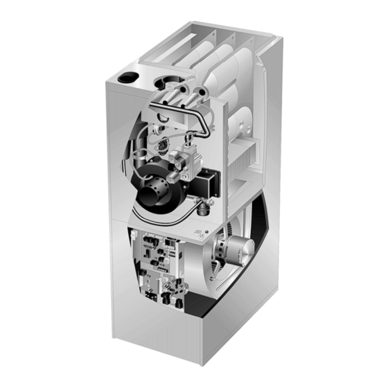
G32V FURNACEY
AG32V HEAT EXCHANGE ASSEMBLY
Combustion Process:
1. A call for heat starts the combustion air blower.
2. Outdoor air is drawn through pipe into the burner
compartment where it mixes with gas in a con-
ventional style inshot burner.
3. The SureLight ignition system lights the burners.
4. Combustion products are drawn downward
through the heat exchanger. Heat is extracted
as indoor air passes across the outside surface
of the metal.
5. Latent heat is removed from the combustion
products as air passes through the coil. Conden-
sate (water) is formed as the combustion prod-
ucts cool.
6. As the combustion products exit the coil, con-
densate is collected and drained away.
7. Combustion products are pulled from the heat
exchanger and forced into the flue.
G32V
Corp. 9816−L10
Revised 02−2004
© 1998 Lennox Industries Inc.
Litho U.S.A.
Advertisement
Table of Contents

Related Manuals for Lennox G32V Series


Summary of Contents for Lennox G32V Series
- Page 1 Revised 02−2004 Service Literature G32V SERIES UNITS G32V series units are high−efficiency upflow gas furnaces manufactured with DuralokPlust aluminized steel clamshell-type heat exchangers. G32V units are available in heating capacities of 75,000 to 125,000 Btuh and cooling ap- plications up to 5 tons. Refer to Engineering Handbook for proper sizing.
-
Page 2: Table Of Contents
TABLE OF CONTENTS Specifications ....... . . III Start Up . -
Page 3: Specifications
SPECIFICATIONS Model No. G32V3−75 G32V5−100 G32V5−125 Input Btuh (kW) − High 75,000 (22.0) 100,000 (29.3) 125,000 (36.6) Input Btuh (kW) − Low 51,000 (14.9) 68,000 (19.9) 85,000 (24.9) Output Btuh (kW) − High 67,500 (19.8) 90,000 (26.4) 112,500 (32.9) Output Btuh (kW) − Low 45,900 (13.4) 61,200 (17.9) 76,500 (22.4) -
Page 4: Blower Data
NOTE − Continuous Fan only speed is approximately 800 cfm (380 L/s) − non adjustable. NOTE − Lennox Harmony IIt zone control applications − MAX CFM is determined by COOL jumper placement with a minimum of approximately 850 cfm (400 L/s) for all positions. - Page 5 NOTE − Continuous Fan only speed is approximately 1150 cfm (545 L/s) − non adjustable. NOTE − Lennox Harmony IIt zone control applications − MAX CFM is determined by COOL jumper placement with a minimum of approximately 1140 cfm (540 L/s) for all positions.
- Page 6 NOTE − Continuous Fan only speed is approximately 1150 cfm (545 L/s) − non adjustable. NOTE − Lennox Harmony IIt zone control applications − MAX CFM is determined by COOL switch setting with a minimum of approximately 1140 cfm (540 L/s) for all positions.
-
Page 7: High Altitude
HIGH ALTITUDE INFORMATION No gas pressure adjustment is needed when operating from 0 to 4500 ft. (0 to 8 m). See below for correct manifold pressures for altitudes greater that 4500 ft. (1372 m) for natural and L.P. gas. Manifold Absolute Pressure (outlet) in. w.g. (kPa) Model No. -
Page 8: Parts Arrangement
G32V PARTS ARRANGEMENT FLUE COLLAR TOP CAP FRESH AIR WARM INTAKE FITTING HEADER GLASS FIBER GASKET (COLLECTOR) BURNER BOX ASSEMBLY CABINET PATCH PLATE WITH BARBED FITTING AND FLAME PATCH ROLL−OUT SWITCH PLATE FLUE DuralokPlus TRANSITION HEAT EXCHANGER ASSEMBLY LOW HEAT DIFFERENTIAL PRESSURE FLAME SIGHT... - Page 9 G32V HEAT EXCHANGER FRESH AIR INTAKE SURELIGHT IGNITOR LENNOX DURALOKPLUS FITTING CORBEL ORIFICE HEAT EXCHANGER ASSEMBLY BURNER BURNER BOX CUPS ACCESS COVER MANIFOLD GAS VALVE WARM HEADER COMBUSTION AIR (COLLECTOR) BLOWER MOTOR COMBUSTION COLD HEADER AIR BLOWER (COLLECTOR ) CONDENSER COIL...
-
Page 10: I Unit Components
MAKE-UP BOX INSTALLATION OUTSIDE INSTALLATION Box may be installed inside or outside cabinet and INSIDE INSTALLATION may be installed on left side or right side of cabinet MAKE-UP BOX STAR WASHERS MAKE-UP BOX MUST BREAK PAINT ON UNIT CABINET FOR PROPER GROUND. -
Page 11: Surelight Ignition System
13/32’ result if repair is attempted. 4.SureLight Ignition System A92 G32V−1 through −4 units are equipped with the Lennox SureLight ignition system. The system consists of ignition control board (figure 8 with control terminal designations in table 1) and ignitor (figure 9). The board and ignitor work in combination to ensure furnace ignition and ignitor dura- bility. - Page 12 TABLE 7 SURELIGHT CONTROL TERMINAL DESIGNATIONS ACB COOL NOT USED ACB HEAT NOT USED PARK NOT USED ACB LOW NOT USED ACCESSORY TERMINAL (LINE VOLT) 120VAC TRANSFORMER 120VAC HOT INPUT HTG ACC HEAT ONLY ACCESSORY (LINE VOLT) NEUTRALS 120VAC NEUTRALS 24VAC HOT 24VAC HOT FROM TRANSFORMER 24VAC RTN...
-
Page 13: Two−Stage Ignition Control
Electronic Ignition (See Ignition Sequence Below) 5. Two−Stage Control (A86) On a call for heat the SureLight control monitors the com- G32V−1 through −4 units bustion air blower pressure switch. The control will not be- G32V−1 through −4 units are equipped with a two−stage gin the heating cycle if the pressure switch is closed (by−... -
Page 14: Vsp2−1
6.VSP2−1 Blower Control Board (A24) G32V −1 / −3 units TWO−STAGE CONTROL BOARD G32V units are equipped with a variable speed motor that is capable of maintaining a specified CFM throughout the ex- ternal static range. The unit uses the VSP2−1 variable speed control board, located in the blower compartment, which controls the blower speed and provides diagnostic W2 TIMED ON... - Page 15 IMPORTANT VSP2−1 BLOWER CONTROL BOARD (A24) 24 VAC half wave rectified (DC pulse), when measured with a meter, may appear as a lower HIGH ADJUST HEAT or higher voltage depending on the make of the TEST meter. Rather than attempting to measure the −...
- Page 16 NOTE−On Harmony II zoning applications in the heating mode, When W1 is energized, the LOW jumper selections are ac- the highest speed obtainable is the same as the highest cool- tivated. The HEAT jumper selections are activated when ing speed selection. Also, the heating speed (heat jumper posi- W2 is energized.
- Page 17 NOTE If fan OFF" time is too low, residual heat in heat in relation to specific modes of operation. Some informa- exchanger may cause primary limit S10 to trip resulting tion has been repeated from the previous section to provide in frequent cycling of blower.
-
Page 18: Vsp3−1
7.VSP3−1 Blower Control Board (A24) Diagnostic LEDs located on the VSP3−1 control board are pro- G32V−4 Units vided to aid in identifying the unit’s mode of operation. Certain scenarios will arise depending on the jumper positions. Refer G32V−4 units are equipped with a variable speed motor that to figure 14 for identification. - Page 19 Diagnostic LED Lights VSP3−1 BLOWER CONTROL BOARD (A24) DS3 ON/OFF ON/OFF−DS3 indicates there is a demand for the blower motor to run. When the ON/OFF LED−DS3 is lit, a demand DELAY COOL ADJUST HEAT is being sent to the motor. In heating mode only, there is a TEST −...
- Page 20 TABLE 13 #1 PIN JUMPERED VSP FACTORY SETTINGS FOR G32V−4 UNITS A − Motor runs at 100% until demand is satisfied. B − Once demand is met, motor ramps down to off. MODEL DELAY COOL ADJUST HEAT NUMBER G32V3−75 NORM 100% CFM COOLING G32V5−100...
- Page 21 TABLE 14 G32V−4 UNITS WITH CCB1, & TWO−SPEED OUTDOOR UNIT OPERATING SEQUENCE Operating Sequence System Demand System Response System Thermostat *Relative Humidity ***Compressor Blower CFM Step Comments Condition Demand (EfficiencyPlus Lights) Speed (COOL) 55% of Acceptable (None) Compressor demand and indoor HIGH COOL Normal operation Normal operation...
-
Page 22: Surelight Two Stage Variable Speed Control
(first stage) heat speed. G32V−75 Only G32V−5 and later units are equipped with the Lennox two− At the beginning of the heat cycle the SureLight control stage, variable speed integrated SureLight control board. monitors the first and second stage combustion air inducer The system consists of a ignition / blower control board prove switches. - Page 23 Once the prove switch (first stage prove switch for G32V−75) is determined to be open, the combustion air in- ducer is energized on low (first stage) heat speed. When the differential in the prove switch is great enough, the TW0−STAGE, VARIABLE SPEED INTEGRATED prove switch closes and a 15−second pre−purge begins.
- Page 24 TABLE 16 TABLE 18 Two Stage Ignition / Blower Control Terminals SureLight Board 12Pin Terminal Designation LINE Line 120VAC Neutral PIN # Function XFMR Transformer 120VAC Neutral Gas Valve High Fire Electronic Air Cleaner 120VAC Neutral Second Stage Prove Switch (G32V−75) CIRC Indoor Blower 120VAC Neutral Not Used...
- Page 25 (2) second pauses. One blink equals roughly 100 CFM. DS7−ON indicaties the DS to R" jumper has not been cut. When the jumper is cut the system will be operating with LENNOX HARMONY IIt (See Harmony Installation Instructions) or with YELLOW the CCB1 Efficiency Plus control.
- Page 26 Dip Switch Settings Switches 7 and 8 −− Blower Speed Adjustment −− Switches 1 and 2 −− Blower Off Delay −− The blower−on Switches 7 and 8 are used to select blower speed adjust- delay of 45 seconds is not adjustable. The blower−off delay ment settings.
- Page 27 G32V units manufactured before April 2003 G32V units manufactured April 2003 and later Ramping Option A (Factory Selection) Ramping Option A (Factory Selection) D Motor runs at 50% for 1/2 minute. S Motor runs at 50% for 30 seconds. D Motor then runs at 82% for approximately 7−1/2 min- S Motor then runs at 82% for approximately 7−1/2 min- utes.
- Page 28 Switches 11 and 12 −− Heating Mode Blower Speed −− On−Board Jumper W951 On−board jumper W951, which connects terminals R and O Switches 11 and 12 are used to select heating mode blower on the integrated control board, must be cut when the fur- motor speed.
- Page 29 TABLE 28 G32V−5, CCB1 and Two−Speed Outdoor Unit OPERATING MODE SYSTEM DEMAND SYSTEM RESPONSE System Thermostat *Relative Humidity ****Compressor Blower CFM Comments Condition Demand (EfficiencyPlus Lights) Speed (COOL) 55% of Compressor demand and indoor No demand. Acceptable HIGH COOL Normal operation Normal operation blower speed controlled by blower speed controlled by...
-
Page 30: Blower Compartment
COIL WHEEL MOTOR (B6) CHOKE G32V series blower motor ratings are listed in table 29. (L13) All G32V blower motors use single phase power. An ex- To Remove Blower From Unit: Remove Bolts and Wiring Jackplugs. Then Slide Out Front of Unit. - Page 31 When Harmony is used, speed taps are overridden and a TABLE 29 ELECTRONICALLY CONTROLLED BLOWER MOTOR PWM signal generated by the Harmony controller continuously CCW ROTATION varies motor speed based upon zone demands. Unit Volts Phase Initial Power Up G32V3 When line voltage is applied to B3, there will be a large inrush G32V5 of power lasting less than 1/4 second.
- Page 32 MOTOR SPEED CONTROL WITH D.C. PULSE-WIDTH MODULATION Motor speed is determined by the size of the electrical pulse sent to the motor windings. The longer the pulse, the faster the motor. OUTPUT FROM CONTROLLER TO MOTOR WINDINGS WINDINGS TURNED OFF WINDINGS TURNED ON Ç...
- Page 33 External Operation (Speed Tap Priority) DANGER Figure 22 shows the two quick-connect jacks (J48 and J49) which connect the motor to the G32V. Jack J48 is the power Do not attempt to repair electronically controlled plug and jack J49 connects the unit controls to the motor. blower motor or VSP.
-
Page 34: Heating
Each orifice and burner are sized specifically to the unit. Re- sensed in the heat exchanger, the limit will open. If the limit fer to Lennox Repair Parts Listing for correct sizing informa- is tripped, the furnace control energizes the supply air blow- tion. - Page 35 6.Gas Valve WHITE RODGERS 36E SERIES GAS VALVE PROPANE GAS The G32V uses gas valves manufactured by White Rodg- HIGH HEAT MANIFOLD ers or Honeywell. The valves are two-stage internally re- PRESSURE dundant to assure safety shut−off. If the gas valve must be ADJUSTMENT ON SIDE replaced, the same type valve must be used.
- Page 36 (Combustion Air Prove Switch) .40 $ .05 S102 75,000 75,000 All G32V series units are equipped with a proving switch .20 $ .05 btuh S128 S102 located on the vestibule panel.The G32V−75 unit only, is equipped with a second prove switch S128. The switches 100,000 .25 $ .05...
- Page 37 CHART REPESENTS NORMAL OPERATING CHARACTERISTICS OF THE PRESSURE SWITCH ONLY AND SHOULD NOT BE USED FOR TROUBLSHOOTING −1.2 DIFFERENTIAL SWITCH CLOSED −1.0 −0.8 −0.6 DIFFERENTIAL SWITCH OPEN (Furnace will not operate) −0.4 −0.2 −0.2 −0.4 −0.6 −0.8 −1.0 −1.2 BURNER BOX STATIC PRESSURE FIGURE 32 Temporarily jumpering the pressure switch when trouble- Measuring pressure differential...
-
Page 38: Placement And Installation
9 − Operate unit and observe draft gauge reading. Read- 6 − Promptly apply solvent cement to end of pipe and in- ings will change as heat exchanger warms. side socket surface of fitting. Cement should be ap- a. Take one reading immediately after startup. plied lightly but uniformly to inside of socket. - Page 39 Intake Piping 1 − Seal any unused openings in the common venting sys- tem. 1 − Cement intake piping in slip connector located at top of unit. 2 − Visually inspect the venting system for proper size and 2 − Route piping to outside of structure. Continue with horizontal pitch and determine there is no blockage or installation following instructions given in exhaust and restriction, leakage, corrosion and other deficiencies...
- Page 40 Heating cable installation prove the velocity of exhaust away from the intake pip- kit is available from Lennox. See Condensate Piping sec- ing. tion for part numbers.
- Page 41 7 − On field supplied terminations, a minimum separation IMPORTANT distance between the end of the exhaust pipe and the For Canadian Installations Only: end of the intake pipe is 8" (203mm). In accordance to CAN/CGA−B149.1 and .2, the minimum allowed distance between the combus- 8 −...
- Page 42 the Natural Gas and Propane Installation Instructions in 10− Suspend piping using hangers at a minimum of every 5 Canada for details. The termination should be at least feet (1.52m) for schedule 40 PVC and every 3 feet 12" (305mm) from any opening through which flue (.91m) for ABS−DWV, PVC−DWV, SPR−21 PVC, and products could enter the building.
- Page 43 EXHAUST Front View (229) (127) VENT Front View EXHAUST VENT (305) NOTE−Enclosed exhaust 5−1/2 INTAKE VENT pipe is insulated with 1/2" (140) INTAKE (13mm) foam insulation. VENT If intake and exhaust pipes are reversed, slit (864) 18 MAX. and remove foam insula- (457) tion and reapply to other Inches (mm)
- Page 44 Heating cable Install the nipple/adapter assembly from the outside kit is available from Lennox in various lengths; 6ft. of the cabinet and insert the adapter into the threaded (1.8m) − kit no. 18K48; 24ft. (7.3m) − kit no. 18K49; and opening in the condensate trap.
- Page 45 G32V CONDENSATE REMOVAL PROCESSB Condensate Removal Process: 1. Condensate mixed with flue products exits DETAIL OF the coil and enters the cold header box. FLUE TRAPB 2. Condensate and flue products are separated. Flue products are drawn into the combustion air blower while condensate is drained into the COLD header box condensate trap.
-
Page 46: Start Up
III−START-UP How To Operate Gas Valve (Figure 50) A−Preliminary and Seasonal Checks WARNING 1 − Inspect electrical wiring, both field and factory installed for loose connections. Tighten as required. 2 − Check voltage at disconnect switch. Voltage must be If you do not follow these instructions exactly, a within range listed on the nameplate. -
Page 47: Heating System Service Checks
12− If the appliance will not operate, follow the instructions TABLE 32 Propane Gas To Turn Off Gas To Unit" and call your service techni- Hi Fire CO Low Fire CO cian or gas supplier. G32VUnit G32VUnit Min Vent Max Vent Min Vent Max Vent Turning Off Gas To Unit... - Page 48 Use of a specialty BARB Gas Leak Detector is strongly recommended. It is available through Lennox under part number 31B2001. BURNER Do not use matches, candles, flame or any other source of SENSING ignition to check for gas leaks.
-
Page 49: Typical Operating Characteristics
SureLight control. Use a flame signal transducer (part 2 − Set thermostat to highest setting. number 78H5401) available from Lennox to measure the 3 − After plenum thermometers have reached their highest flame signal, if meter used will not read microamp signal. -
Page 50: Maintenance
418 and is available as Lennox part no. P-8-5069. 13− Drain condensate trap. Disconnect condensate line 3 − If replacement is necessary, order Lennox part no. from the outside of unit. Remove condensate line from 31J81 for 14" x 25" (356 x 635mm) filter for condensate trap by turning the adapter fitting counter- G32VQ3−75 units and P-8-7831 for 20"... - Page 51 34− Re-install electrical connections to gas valve. Brown 16− Disconnect 9-pin plug from the blower compartment at the blower deck. wire to H1, yellow wire to C2 and orange wire to M. Re- connect wires to flame roll-out switch. 17− Remove 9-pin plug above the blower deck. NOTE −...
- Page 52 NOTE − Ignitor must be installed on the opposite side of C−Supply Air Blower the burner from the metal button protrusions. Screws 1 − Check and clean blower housing and blower wheel. which attached the ignitor bracket must be installed from 2 −...
-
Page 53: Wiring Diagrams And Operating Sequence
VII−WIRING DIAGRAM & SEQUENCE OF OPERATION G32V −1 UNITS SCHEMATIC WIRING DIAGRAM Page 53... -
Page 54: G32V−3
G32V −3 UNITS SCHEMATIC WIRING DIAGRAM Page 54... -
Page 55: G32V−4
G32V −4 UNITS SCHEMATIC WIRING DIAGRAM Page 55... - Page 56 A−Sequence of Operation 2 − SureLight control energizes ignitor. A 20−second warm−up period begins. Ignitor operation will vary between SureLight boards. Board 3 − Gas valve is energized on first stage. Gas valve opens 63K89, 56L83 and 24L85 will energize ignitor for the first for a 4−second trial for ignition.
- Page 57 HEATING SEQUENCE OF OPERATION NOTE: LED REFERS TO SURELIGHT CONTROL . LED−DS REFERS TO VSP CONTROL. NORMAL HEATING MODE ABNORMAL HEATING MODE GAS VALVE OFF. COMBUSTION AIR INDUCER OFF. POWER ON INDOOR BLOWER DELAY OFF. LED #1 ON LED #2 ON CONTROL SELF−CHECK OKAY? (RESET CONTROL BY TURNING MAIN POWER OFF.) COMBUSTION AIR INDUCER ON FOR 1 SECOND.
- Page 58 HEATING SEQUENCE CONTINUED NORMAL HEATING MODE ABNORMAL HEATING MODE PREPURGE 15 SECONDS WATCHGUARD 60-MINUTE DELAY (SIGNAL LIMIT OR IGNITION FAILURE) GAS VALVE OFF. COMBUSTION AIR AND INDOOR BLOWER OFF. LED #1 AND LED #2 ALTERNATING SLOW FLASHES IGNITION SEQUENCE BEGINS (Ignition trial counter initiated.) WATCHGUARD −−...
- Page 59 HEATING SEQUENCE CONTINUED NORMAL HEATING MODE ABNORMAL HEATING MODE PREPURGE (See top of previous page.) PROVE SWITCH CLOSED? GAS VALVE DE−ENERGIZED. INDOOR BLOWER DE−ENERGIZED. TWO−STAGE MODE W2 TIMED MODE COMBUSTION AIR INDUCER ON FOR 2.5 MINUTES. CALL FOR 1st STAGE HEAT SINGLE STAGE T’STAT PROVE SWITCH CALL FOR 2nd STAGE...
- Page 60 COOLING SEQUENCE OF OPERATION NORMAL COOLING MODE ABNORMAL COOLING MODE POWER ON IGNITION CONTROL MAIN POWER ON. GAS VALVE OFF. COMBUSTION AIR INDUCER OFF. INDOOR BLOWER OFF WITH NORMAL DELAY. CONTROL SELF DIAGNOSTIC CHECK. SIGNAL CIRCUIT BOARD FAILURE AT LED. IS CONTROL OPERATING NORMALLY? INTERRUPT MAIN POWER TO RESET CONTROL.
- Page 61 SURELIGHT CONTROL CONTINUOUS LOW SPEED FAN SEQUENCE OF OPERATION LED: SLOW FLASH RATE REMAINS UNCHANGED THROUGHOUT SEQUENCE. MANUAL FAN SELECTION MADE AT THERMOSTAT. CONTROL (G) ENERGIZES SYSTEM FAN AT ACB LOW SPEED. ACC. TERMINAL IS ENERGIZED. HTG ACC. TERM. ENERGIZES THERMOSTAT CALLS FOR HEAT (W).
-
Page 62: G32V−5
G32V −5, −6 UNITS SCHEMATIC WIRING DIAGRAM Page 62... - Page 63 Single−Stage Thermostat, Two Stage Heat. Jumper B−Sequence of Operation. E20 set at SINGLE" Sequence depends on type thermostat used. Units are 1− SureLight control energizes combustion air inducer B6 applicable for single stage or two stage thermostats. on low heat speed. Combustion air inducer runs until Both type thermostats are described below.
- Page 64 HEATING SEQUENCE OF OPERATION NORMAL AND ABNORMAL HEATING MODE GAS VALVE OFF. COMBUSTION AIR INDUCER POWER ON OFF. INDOOR BLOWER OFF. CHECK FOR BROKEN IGNITOR OR OPEN IGNITER CIRCUIT. DS 1 AND DS 2 ALTERNATING FAST FLASH. CONTROL SELF−CHECK OKAY? GAS VALVE OFF.
- Page 65 HEATING SEQUENCE OF OPERATION CONTINUED THERMOSTAT CALLS FOR HEAT DS1 AND DS2 SIMULTANEOUS FAST FLASH (Refer to box A on previous page) FIRST−STAGE (LOW−FIRE) PRESSURE GAS VALVE OFF. COMBUSTION AIR INDUCER SWITCH CLOSED WITHIN 2.5 MINUTES? OFF. INDOOR BLOWER OFF. UNIT WILL RETRY AFTER 5−MINUTE WAIT PERIOD.
- Page 66 HEATING SEQUENCE OF OPERATION CONTINUED THERMOSTAT CALLS FOR HEAT. DS1 AND DS2 SIMULTANEOUS FAST FLASH. SEE BOX A. FLAME SIGNAL ABOVE (u0.23 microamps) LOW FLAME SIGNAL (Does not affect control operation) DS1 SLOW FLASH, DS2 FAST FLASH. SINGLE−STAGE THERMOSTAT MODE TWO STAGE THERMOSTAT MODE (E20 SET AT SINGLE") (E20 SET AT TWO")
- Page 67 HEATING SEQUENCE OF OPERATION CONTINUED SEE BOX A NORMAL OPERATION DS1 AND DS2 SIMULTANEOUS SLOW FLASH. SEE BOX B THERMOSTAT CALLS FOR HEAT DS 1 AND DS 2 SIMULTANEOUS FAST FLASH. GAS VALVE OFF. COMBUSTION AIR INDUCER OFF. INDOOR BLOWER ON. ARE PRIMARY LIMIT AND ROLLOUT DS1 SLOW FLASH, DS2 ON, SWITCH CLOSED?
- Page 68 COOLING SEQUENCE OF OPERATION POWER ON IS POLARITY REVERSED? SIGNAL POLARITY REVERSED. DS1 FAST FLASH, DS2 SLOW FLASH. SIGNAL IMPROPER GROUND AT DS. IS THERE IS VOLTAGE SIGNAL HOLDS LOW VOLTAGE SIGNAL AT DS HOLDS PROPER GROUND? ABOVE 75 VOLTS? UNTIL VOLTAGE RISES ABOVE 75 VOLTS.
- Page 69 CONTINUOUS LOW SPEED FAN SEQUENCE OF OPERATION MANUAL FAN SELECTION MADE AT THERMOSTAT. AFTER 2 SECOND DELAY, INDOOR BLOWER IS ENERGIZED ON CONTINUOUS FAN SPEED. THERMOSTAT CALLS FOR FIRST STAGE COOL. THERMOSTAT CALLS FOR FIRST−STAGE HEAT. INDOOR BLOWER RAMPS TO FIRST STAGE AFTER 45−SECOND DELAY, INDOOR BLOWER COOLING SPEED AFTER A 2−SECOND DELAY.
-
Page 70: Vsp2−1 Jumper Summary
TABLE 35 G32V−1 / −3 OPERATION SEQUENCE AND JUMPERS SUMMARY WITH VSP2 (HEATING) MATCH UP T−Strip Mode of COMMENTS OR SEQUENCE Jumper Operation Jumper FOR COOLING JUMPERS SEE COOLING SECTION BELOW Single-Stage Heating One−Stage Blower operates on the high with Single−Stage Jumpers speed heat tap during the Thermostat... - Page 71 (continued from previous page) G32V−1 / −3 OPERATION SEQUENCE AND JUMPERS SUMMARY WITH VSP2 (HEATING CONTINUED) MATCH UP T−Strip Mode of COMMENTS OR SEQUENCE Jumper Operation Jumper Two−Stage Heating Two−Stage Blower operates on the low With Two−Stage Jumpers speed heat/cool tap during first Thermostat stage heating.
- Page 72 (continued from previous page) G32V−1 / −3 OPERATION SEQUENCE AND JUMPERS SUMMARY WITH VSP2 (COOLING CONTINUED) MATCH UP T−STRIP JUMPER COMMENTS OR SEQUENCE FOR HEATING JUMPERS SEE HEATING SECTION ABOVE Blower speed is controlled by the DC signal from CCB1. No Jumpers Blower operates on low speed CCB1 with Single-Speed...
- Page 73 (continued from previous page) G32V−1 / −3 OPERATION SEQUENCE AND JUMPERS SUMMARY WITH VSP2 (COOLING CONTINUED) T−STRIP JUMPER MATCH UP COMMENTS OR SEQUENCE WIRING CONNECTIONS FOR HEATING JUMPERS SEE SEE HEATING SECTION ABOVE Remove pin #3 of the J73 terminal on the VSP con- No Jumpers trol.
-
Page 74: Vsp3−1 Jumper Summary
TABLE 36 G32V−4 OPERATION SEQUENCE AND JUMPERS SUMMARY WITH VSP3 (HEATING) T−Strip Mode of COMMENTS OR SEQUENCE MATCH UP WIRING CONNECTIONS Jumper Operation Jumper FOR COOLING JUMPERS SEE COOLING SECTION Blower operates on BELOW One−Stage high speed during the Jumpers Single-Stage Heating heating mode. - Page 75 (continued from previous page) G32V−4 OPERATION SEQUENCE AND JUMPERS SUMMARY WITH VSP3 (HEATING CONTINUED) MATCH UP T−Strip Mode of WIRING CONNECTIONS COMMENTS OR SEQUENCE Jumper Operation Jumper Blower operates on low Two−Stage Heating Two−Stage speed during first stage With Two−Stage Jumpers heating.
- Page 76 (continued from previous page) G32V−4 OPERATION SEQUENCE AND JUMPERS SUMMARY WITH VSP3 (COOLING CONTINUED) T−STRIP JUMPER MATCH UP COMMENTS OR SEQUENCE WIRING CONNECTIONS Blower speed is controlled Y1 to Y2 FOR HEATING JUMPERS by the DC signal from SEE HEATING SECTION ABOVE CCB1.
- Page 77 (continued from previous page) G32V−4 OPERATION SEQUENCE AND JUMPERS SUMMARY WITH VSP3 (COOLING CONTINUED) MATCH UP T−STRIP JUMPER COMMENTS OR SEQUENCE WIRING CONNECTIONS Remove the wire from Pin #2 and Pin #13 of the J49 harness connec- tor at the motor and the wire from Y1 to Y2 FOR HEATING JUMPERS Pin #3 of the J73 harness connec-...
-
Page 78: Surelight Jumper Summary
G32V−5 Units with Two Stage Variable Speed Control TABLE 37 Field Wiring Applications Jumper Settings (See figure 16) Thermostat Thermostat Wiring Connections Wiring Connections W915 W914 W951 1 Heat / 1 Cool SINGLE Intact Intact CONTROL OUTDOOR T’STAT TERM. STRIP UNIT NOTE −... - Page 79 TABLE 37 Field Wiring Applications (Continued) Jumper Settings (See figure 16) Thermostat Thermostat Wiring Connections Wiring Connections W915 W914 W951 1 Heat / 2 Cool SINGLE Intact Intact CONTROL OUTDOOR T’STAT TERM. STRIP UNIT NOTE − Use dip switch 3 to set second−stage heat ON delay.
- Page 80 TABLE 37 Field Wiring Applications (Continued) Jumper Settings (See figure 16) Thermostat Thermostat Wiring Connections Wiring Connections W915 W914 W951 2 Heat / 1 Cool Intact Intact CONTROL OUTDOOR T’STAT TERM. STRIP UNIT FM21 Heat SINGLE Intact CONTROL FM21 TERM. STRIP Pump / 1 Cool *Disconnect existing furnace transformer and...
-
Page 81: Troubleshooting
VIII− Troubleshooting 1− VSP2−1 Blower Control Board G32V−1 / −3 Units DOES UNIT OPERATE? CHECK: 1−UNIT POWER IS 24VAC ACROSS 2−INTERLOCK SWITCH R AND C? 3−TRANSFORMER COOLING MODE 4−LIMIT SWITCH PLACE JUMPER ACROSS R AND G. IS BLOWER ON LOW SPEED AND IS ON/OFF"... -
Page 82: Vsp3−1 Board
2− VSP3−1 Blower Control Board G32V−4 Units DOES UNIT OPERATE? CHECK: 1−UNIT POWER IS 24VAC ACROSS 2−INTERLOCK SWITCH R AND C? 3−TRANSFORMER COOLING MODE 4−LIMIT SWITCH PLACE JUMPER ACROSS R, G, AND Y1. IS BLOWER ON LOW SPEED AND IS ON/ OFF LED−DS3 AND HI/LOW LED−DS1 LIT? CHECK UNIT WIRING AND IF CFM LED−DS4 LIGHT SHOULD BLINK... -
Page 83: Icm2 Motor With Vsp2−1
A kit is available from the Lennox parts center to use in testing the variable speed motor. The kit 70J11 includes a test plug harness to facilitate ICM−2 check−out. Follow testing procedures outlined in the instructions provided with the kit. -
Page 84: Icm2 Motor With Vsp3−1
ICM−2 WITH VSP3 120V to the motor must not be interrupted. All connections for check out will be from the volt- age source below (battery or 24V) to plug J46, after disconnecting from blower control board. CHECK−OUT PROCEDURE USING 24V SOURCE CHECK−OUT PROCEDURE USING BATTERY Unit transformer T1 with a maximum AC 30 volts An ordinary 9 volt battery with maximum DC... -
Page 85: Icm2 Motor With Surelight Control
ICM−2 WITH TWO STAGE VARIABLE SPEED CONTROL BOARD 120V to the motor must not be interrupted. All connections for check out will be from the volt- age source below (battery or 24V) to plug J46, after disconnecting from blower control board. REMOVE PLUG FROM BOARD CHECK−OUT PROCEDURE USING BATTERY An ordinary 9 volt battery with maximum DC... -
Page 86: Surelight Control
4− SureLight Control Board UPON INITIAL POWER UP, REMOVE ALL THERMOSTAT DEMANDS TO THE UNIT Unless otherwise noted, condition applies to all G32V units. PROBLEM: 1 UNIT FAILS TO OPERATE IN THE COOLING, HEATING, OR CONTINUOUS FAN MODE Condition Possible Cause Corrective Action / Comments 1.1.1 ACTION 1 −... - Page 87 PROBLEM 1: UNIT FAILS TO OPERATE IN THE COOLING, HEATING, OR CONTINUOUS FAN MODE Condition Possible Cause Corrective Action / Comments ACTION 1 − Check that the unit is properly 1.5.1 grounded. − On initial power−up the combustion ACTION 2 − Install a proper main ground to the Improper ground to the unit.
- Page 88 PROBLEM 3: UNIT FAILS TO FIRE IN THE HEATING MODE, COMBUSTION AIR BLOWER DOES NOT ENERGIZE (CONT.). Condition Possible Cause Corrective Action/Comments − Unit operates with a cooling and con- 3.3.1 ACTION 1 − Check for correct wiring and loose tinuous fan demand.
- Page 89 PROBLEM 5: UNIT FAILS TO FIRE IN THE HEATING MODE, COMBUSTION AIR BLOWER ENERGIZES, IGNITOR IS ENERGIZED. (CONT.) Condition Possible Cause Corrective Action/Comments ACTION 1 − Check line pressure at the gas valve. 5.1.1 Pressure should not exceed 13" WC for both nat- −...
- Page 90 LED#2−On bustion air blower. changer to proper Lennox personnel. ACTION 1 − Check for sooting deposits or other restrictions in the heat exchanger assembly. Clean assembly as outlined in instruction manu- 6.3.4...
- Page 91 PROBLEM 6: BURNERS LIGHT WITH HEATING DEMAND BUT UNIT SHUTS DOWN PREMATURELY (CONT.) − Combustion air blower energizes with a heating demand. − Burners light. − Diagnostic lights flash watch guard ACTION 1 − Check that the sensor is properly lo- 6.5.1 flame failure.