Table of Contents
Advertisement
E 2006 Lennox Industries Inc.
Dallas, Texas, USA
HOMEOWNER FOR FUTURE REFERENCE
Do not store or use gasoline or other
flammable vapors and liquids in the
vicinity of this or any other ap-
pliance.
Installation and service must be
performed by a qualified installer,
service agency or the gas supplier.
10/09
*2P1009*
INSTALLATION
INSTRUCTIONS
G40DF(X) Series
GAS FURNACE
505,253M
10/2009
Supersedes 05/2009
Table of Contents
WARNING
FIRE OR EXPLOSION HAZARD.
Failure to follow safety warnings exact-
ly could result in serious injury, death,
or property damage.
WHAT TO DO IF YOU SMELL GAS:
D Do not try to light any appliance.
D Do not touch any electrical switch; do not
use any phone in your building.
D Leave the building immediately.
D Immediately call your gas supplier from a
neighbor's phone. Follow the gas supplier's
instructions.
D If you cannot reach your gas supplier, call
the fire department.
Page 1
. . . . . . . . . . . . . . . . . . . . . . .
. . . . . . . . . . . . . . . . . . . . .
. . . . . . . . . . . . . . . . . . . . . . . . . .
. . . . . . . . . . . . . . . . . . . . . . . .
. . . . . . . . . . . . . . . . . . . . . . . . . . . . . . .
. . . . . . . . . . . . . . . . . . . . . . . . . . . . . . . . . . . . . . . .
. . . . . . . . . . . . . . . . . . . . . . . . . . . .
. . . . . . . . . . . . . . . . . . . . . . . . . . . . . . .
. . . . . . . . . . . . . . . . . . . . . . . . . . . . . . . . . . . . . . . . .
. . . . . . . . . . . . . . . . . . . . . . . . . . . . . . . . . . .
. . . . . . . . . . . . . . . . . . . . . . . . . . . . . . . . . . . . . . .
. . . . . . . . . . . . . . . . . . . . . . . . . . . . . . . . . . . .
. . . . . . . . . . . . . . . . . . . . . . . . . . . . . . . . . . . . . .
. . . . . . . . . . . . . . . . . . . . . . . . . . . . . . . . . . .
. . . . . . . . . . . . . . . . . . . . . . .
. . . . . . . . . . . . . . . . . . . . . . . .
. . . . . . . . . . . . . . . . . . . . . . . . . .
. . . . . . . . . . . . . . . . . . . . . . . . . . . .
. . . . . . . . . . . . . . . . . . . . . . . . . . . . . . . . . . . . . . .
. . . . . . . . . . . . . . . . . . . . . . . . . . . . . . . .
. . . . . . . . . . . . . . . . . . . . . . . . . . . . . . .
. . . . . . . . . . . . . . . . . . . . . . . . . . . . . . . .
*P505253M*
Litho U.S.A.
2
3
4
4
4
5
. . . . . . . . . . . . .
5
. . . . . . . . . . . . .
6
8
9
10
10
10
18
19
23
24
25
25
26
28
30
30
. . . . . . . . . . .
31
32
. . . . . .
35
505,253M
Advertisement
Table of Contents
Troubleshooting

Related Manuals for Lennox G40DF Series


Summary of Contents for Lennox G40DF Series
-
Page 1: Table Of Contents
INSTALLATION INSTRUCTIONS E 2006 Lennox Industries Inc. Dallas, Texas, USA G40DF(X) Series GAS FURNACE 505,253M 10/2009 Supersedes 05/2009 Litho U.S.A. Table of Contents G40DF(X) Unit Dimensions ..... . . -
Page 2: G40Df(X) Unit Dimensions
G40DF(X) Unit Dimensions − inches (mm) 3−3/4 (95) 5/8 (16) RETURN AIR OPENING FLUE OUTLET 19−1/2 (Top) (16) (495) 5/8 (16) TOP VIEW 28−1/2 (724) 19−1/2 (16) (16) (495) AIR FLOW (1016) ELECTRICAL INLET (Either Side) 4−7/8 (124) Right GAS PIPING INLET 2−1/4 (57) Left (Either Side) 9−1/4... -
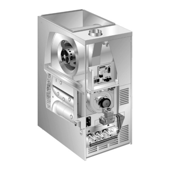
Page 3: G40Df(X) Parts Arrangement
G40DF(X) Parts Arrangement Blower Assembly Internal Flue Pipe Assembly Blower Motor Gasket Capacitor Transformer Flue Door Chase Interlock Switch Gasket Integrated Ignition Control Board Primary Flue Box Gasket Limit Heat Exchanger Flame Rollout Flame Switches Flue Collector Box Sensor Gasket Gas Valve Combustion Air Orifice... -
Page 4: G40Df(X) Gas Furnace
In the USA, installation of gas furnaces must conform with G40DF(X) Gas Furnace local building codes. In the absence of local codes, units must be installed according to the current National Fuel The G40DF(X) gas furnace is shipped ready for installa- Gas Code (ANSI-Z223.1). -
Page 5: General
The vent system must be permanently installed per these installation instructions. Lennox Industries Inc. P.O. Box 799900 A room thermostat must control the furnace. The use of Dallas, TX 75379−9900 fixed jumpers that will provide continuous heating is not allowed. -
Page 6: Combustion, Dilution, & Ventilation Air
When the furnace is installed in an attic or other insu- CAUTION lated space, keep insulation away from the furnace. Do not install the furnace in a corrosive or contami- Combustion, Dilution, & Ventilation Air nated atmosphere. Meet all combustion and ventila- tion air requirements, as well as all local codes. - Page 7 confined space such as a closet or small equipment room. total input rating of all gas−fired equipment in the confined space. Each opening must be at least 100 square inches Even a small leak around the base of the unit at the platform (64,516 mm ).
-
Page 8: Downflow Installation
Installation on Noncombustible Flooring EQUIPMENT IN CONFINED SPACE 1 − Cut floor opening keeping in mind clearances listed on ALL AIR FROM OUTSIDE unit rating plate. Also keep in mind gas supply connec- (All Air Through Ventilated Attic) CHIMNEY OR GAS tions, electrical supply, flue and air intake connections VENT VENTILATION LOUVERS... -
Page 9: Setting Equipment
2 − After opening is cut, set additive base into opening. 3 − In all cases, plenum should be secured to top flanges of furnace with sheet metal screws. 3 − Check fiberglass strips on additive base to make sure 4 −... -
Page 10: Filters
Filters Downflow Application Installation Clearances This unit is not equipped with a filter or rack. A field−pro- vided high−velocity filter is required for the unit to operate properly. Table 3 lists the recommended minimum filter sizes. A filter must be in place any time the unit is operating. Left Side Right Side TABLE 3... - Page 11 NOTE − Use these instructions as a guide. They do not su- Masonry chimneys used to vent Category I central fur- naces must be either tile-lined or lined with a listed metal persede local codes. This furnace must be vented accord- lining system or dedicated gas vent.
- Page 12 Common Venting Using Tile−Lined Interior Masonry Chimney and Combined Vent Connector MINIMUM LENGTH = AS SHORT AS PRACTICAL. INTERIOR TILE−LINED FOR MAXIMUM LENGTH SEE NOTE TO LEFT MASONRY CHIMNEY NOTE− Refer to provided venting tables for installations in the USA and the venting tables in current CSA−B149 for installations in Canada.
- Page 13 6 − Single appliance venting configurations with zero lat- turer’s instructions. Joints between sections of single wall connector piping shall be fastened by screws or eral lengths (tables 5 and 6), are assumed to have no other approved means. elbows in the vent system. For all other vent configura- tions, the vent system is assumed to have two 90°...
- Page 14 TABLE 5 Capacity of Type B Double−Wall Vents with Type B Double−Wall Connectors Serving a Single Category I Appliance Vent and Connector Diameter − D (inches) Height Lateral 3 Inch 4 Inch 5 Inch 6 Inch Appliance Input Rating in Thousands of Btu Per Hour (feet) (feet) NOTE −...
- Page 15 TABLE 6 Capacity of Type B Double−Wall Vents with Single−Wall Metal Connectors Serving a Single Category I Appliance Vent and Connector Diameter − D (inches) Height Lateral 3 Inch 4 Inch 5 Inch 6 Inch Appliance Input Rating in Thousands of Btu Per Hour (feet) (feet) NOTE −...
- Page 16 TABLE 7 Vent Connector Capacity Type B Double−Wall Vents with Type B Double−Wall Connectors Serving Two or More Category I Appliances Vent and Connector Diameter − D (inches) Vent Connector 3 Inch 4 Inch 5 Inch 6 Inch Height Rise Appliance Input Rating in Thousands of Btu Per Hour (feet) (feet)
- Page 17 TABLE 9 Vent Connector Capacity Type B Double−Wall Vents with Single−Wall Metal Connectors Serving Two or More Category I Appliances Vent and Connector Diameter − D (inches) Vent Connector 3 Inch 4 Inch 5 Inch 6 Inch Height Rise Appliance Input Rating in Thousands of Btu Per Hour (feet) (feet) TABLE 10...
-
Page 18: Gas Piping
Resize the common venting system to the minimum 3 − The gas piping must not run in or through air ducts, clothes chutes, gas vents or chimneys, dumb waiters, vent pipe size determined by using the appropriate or elevator shafts. tables in appendix G. -
Page 19: Electrical
Left Side Piping AUTOMATIC (Standard) GAS VALVE MANUAL MANUAL (with manual AUTOMATIC MAIN SHUT−OFF MAIN SHUT−OFF shut−off valve) GAS VALVE VALVE VALVE (with manual (With 1/8 in. NPT (With 1/8 in. NPT shut−off valve) Plugged Tap Plugged Tap Shown) Shown) GROUND JOINT GROUND... - Page 20 NOTE − The G40DF(X) furnace contains electronic INTERIOR MAKE−UP BOX INSTALLATION components that are polarity sensitive. Make sure that the furnace is wired correctly and is properly grounded. One line voltage EAC" terminal is provided on the fur- nace control board. Any electronic air cleaner rated up to one amp can be connected to this terminal with the neutral leg of the circuit being connected to any of the NEUTRAL"...
- Page 21 TYPICAL G40DF(X) FIELD WIRING DIAGRAM FIGURE 19 INTEGRATED CONTROL BOARD (Automatic Hot Surface Ignition System) TERMINAL DESIGNATIONS Humidifier (120VAC) LINE Input (120VAC) XFMR Transformer (120VAC) Electronic Air Cleaner (120VAC) COOL Blower − Cooling Speed (120VAC) HEAT Blower − Heating Speed (120VAC) PARK Dead terminals to park alternate spd taps FLAME...
- Page 22 G40DF(X) Typical Schematic Wiring Diagram FIGURE 21 Page 22...
-
Page 23: Unit Start−Up
6 − Honeywell VR8205 Gas Valve with ON/OFF Switch Unit Start−Up − Move gas valve switch to OFF. See figure 22. Honeywell VR8205 Gas Valve with Control Knob − FOR YOUR SAFETY READ BEFORE LIGHTING Turn knob on gas valve clockwise to OFF. -
Page 24: Gas Pressure Adjustment
10− Turn on all electrical power to to the unit. 3 − Remove temporary gas meter if installed. 11− Set the thermostat to desired setting. NOTE − To obtain accurate reading, shut off all other gas appliances connected to meter. NOTE −... -
Page 25: High Altitude Information
across the five pins on the integrated control. The unit is High Altitude Information shipped with a factory fan off setting of 90 seconds. The fan NOTE − In Canada, certification for installations at eleva- off delay affects comfort and is adjustable to satisfy individ- tions over 4500 feet (1372 m) is the jurisdiction of local au- ual applications. -
Page 26: Blower Performance
Flue And Chimney 1 − Is the thermostat calling for heat? 2 − Are access panels securely in place? 1 − Check flue pipe, chimney and all connections for tight- ness and to make sure there is no blockage. 3 − Is the main disconnect switch closed? 2 −... - Page 27 Blower Performance NOTE − All air data is measured external to unit with 1 in. cleanable filter (not furnished − field provided) in place. G40DF−48C−110 PERFORMANCE G40DF−60C−110 PERFORMANCE Air Volume / Watts at Different Blower Speeds Air Volume / Watts at Different Blower Speeds External External Medium−...
-
Page 28: This Manual Must Be Left With The Service
2 − Remove the three screws that secure the vent pipe to Service the flue collar. See figure 10. 3 − Remove the screw that secures the internal flue pipe to WARNING the combustion air inducer. See figure 26. 4 − Scrape away the silicone sealant that is between the Disconnect power before servicing unit. - Page 29 8 −Disconnect gas supply piping. Remove four screws se- 15 −Replace collector box and combustion air inducer. curing the burner manifold assembly to the vestibule Check gaskets for damage. Damaged gaskets must panel and remove the assembly from the unit. be replaced to avoid heat exchanger leaks.
-
Page 30: Planned Service
Planned Service A service technician should check the following items dur- Return air duct − Must be properly attached and provide ing an annual inspection. Power to the unit must be shut off an air seal to the unit. for safety. Operating performance −... -
Page 31: Ignition Control Board Diagnostic Codes
Ignition Control Board Diagnostic Codes DIAGNOSTIC CODES Make sure to Identify LED’S Correctly. Refer to figure 20 for control board layout. LED #1 (Red) LED #2 (Green) DESCRIPTION Power on − Normal operation. SIMULTANEOUS SIMULTANEOUS Also signaled during cooling and continuous fan. SLOW FLASH SLOW FLASH SIMULTANEOUS... -
Page 32: Troubleshooting
Troubleshooting: Heating Sequence of Operation HEATING SEQUENCE OF OPERATION ABNORMAL HEATING MODE NORMAL HEATING MODE POWER ON GAS VALVE OFF. COMBUSTION AIR INDUCER OFF. INDOOR BLOWER DELAY OFF. CONTROL SELF−CHECK OKAY? LED #1 ON LED #2 ON (RESET CONTROL BY TURNING MAIN POWER OFF.) POLARITY REVERSED. - Page 33 Troubleshooting: Heating Sequence of Operation (Continued) HEATING SEQUENCE CONTINUED NORMAL HEATING MODE ABNORMAL HEATING MODE 15-SECOND COMBUSTION AIR INDUCER PREPURGE INITIATED BY CLOSED PRESSURE SWITCH. LEDS SIGNAL ALTERNATING FAST FLASH UNTIL IGNITER WARM-UP −− 20 SECONDS. IS VOLTAGE ABOVE 90 VOLTS? VOLTAGE IS ABOVE 95 VOLTS, THEN RESTARTS HEATING...
-
Page 34: Troubleshooting: Cooling Sequence Of Operation
Troubleshooting: Cooling Sequence of Operation COOLING SEQUENCE OF OPERATION NORMAL COOLING MODE ABNORMAL COOLING MODE POWER ON IGNITION CONTROL MAIN POWER ON. GAS VALVE OFF. COMBUSTION AIR INDUCER OFF. INDOOR BLOWER OFF WITH NORMAL DELAY. CONTROL SELF DIAGNOSTIC CHECK. SIGNAL CIRCUIT BOARD FAILURE AT LED. IS CONTROL OPERATING NORMALLY? INTERRUPT MAIN POWER TO RESET CONTROL. -
Page 35: G40Df(X) Start−Up & Performance Check List
Troubleshooting: Continuous Fan Sequence of Operation CONTINUOUS HEAT SPEED FAN SEQUENCE OF OPERATION LED: SLOW FLASH RATE REMAINS UNCHANGED THROUGHOUT SEQUENCE. MANUAL FAN SELECTION MADE AT THERMOSTAT. CONTROL (G) ENERGIZES SYSTEM FAN AT HEAT SPEED. EAC TERMINAL IS ENERGIZED. HUM TERM. ENERGIZES THERMOSTAT CALLS FOR HEAT (W).