Lennox G40UH(X) Unit Information
Hide thumbs
Also See for G40UH(X):
- User's information manual (6 pages) ,
- Installation instructions manual (35 pages) ,
- Installation instructions manual (34 pages)
Table of Contents
Advertisement
Service Literature
G40UH(X) series units are mid−efficiency gas furnaces
used for upflow or horizontal applications only, manufac-
tured with Lennox Duralok Plus heat exchangers formed of
aluminized steel. G40UH(X) units are available in heating
capacities of 44,000 to 154,000 Btuh and cooling applica-
tions up to 5 tons. Refer to Engineering Handbook for prop-
er sizing.
Units are factory equipped for use with natural gas. Kits are
available for conversion to LPG operation. G40UH(X) model
units are equipped with a hot surface ignition system. The
G40UH(X) unit meets the California Nitrogen Oxides (NO
Standards and California Seasonal Efficiency requirements.
All units use a redundant gas valve to assure safety shut−off
as required by C.S.A.
All specifications in this manual are subject to change. Pro-
cedures outlined in this manual are presented as a recom-
mendation only and do not supersede or replace local or
state codes. In the absence of local or state codes, the
guidelines and procedures outlined in this manual (except
where noted) are recommended only and do not constitute
code.
TABLE OF CONTENTS
. . . . . . . . . . . . . . . . . . . . . . . . . . . . .
. . . . . . . . . . . . . . . . . . . . . . . . . . . . . .
. . . . . . . . . . . . . . . . . . . . . . . . . . . . .
. . . . . . . . . . . . . . . . . . . . . . . .
. . . . . . . . . . . . . . . . . . . . . . .
II Installation
. . . . . . . . . . . . . . . . . . . . . . . . . . . . .
III Start Up
. . . . . . . . . . . . . . . . . . . . . . . . . . . . . . .
IV Heating System Service Checks
V Typical Operating Characteristics
VI Maintenance
. . . . . . . . . . . . . . . . . . . . . . . . . .
VII Wiring and Sequence of Operation
VIII SureLight Troubleshooting Guide
Corp. 0006−L3
Revised 09−2006
)
x
Page 2
Page 4
Page 13
Page 14
Page 16
Page 24
Page 24
. . . . . . . . .
Page 24
. . . . . . . . .
Page 28
Page 28
. . . . . .
Page 30
. . . . . . .
Page 41
Page 1
IMPORTANT
Improper installation, adjustment, alteration, service
or maintenance can cause property damage, person-
al injury or loss of life. Installation and service must
be performed by a qualified installer, service agency
or the gas supplier.
WARNING
Electric shock hazard. Can cause injury
or death. Before attempting to perform
any service or maintenance, turn the
Electrical power to unit OFF at discon-
nect switch(es). Unit may have multiple
power supplies.
WARNING
Sharp edges.
Be careful when servicing unit to avoid sharp edges
which may result in personal injury.
G40UH(X)
© 2000 Lennox Industries Inc.
Advertisement
Table of Contents

Related Manuals for Lennox G40UH(X)


Summary of Contents for Lennox G40UH(X)
- Page 1 G40UH(X) series units are mid−efficiency gas furnaces used for upflow or horizontal applications only, manufac- tured with Lennox Duralok Plus heat exchangers formed of aluminized steel. G40UH(X) units are available in heating capacities of 44,000 to 154,000 Btuh and cooling applica- tions up to 5 tons.
-
Page 2: Specifications
SPECIFICATIONS Model No. G40UH G40UH G40UH G40UH G40UH G40UH G40UH −24A−045 −36A−045 −24A−070 −36A−070 −48B−070 −36B−090 −48B−090 Low NO Model No. −24A−045X − − − − − − −36A−070X − − − − − − −48B−090X Input − Btuh 44,000 44,000 66,000 66,000... - Page 3 SPECIFICATIONS G40UH−60C−110 G40UH−60D−135 G40UH−60D−155 Model No. −1, −2, −3 units −1, −2, −3 units −1, −2, −3 units Input − Btuh (kW) 110,000 (32.2) 132,000 (38.7) 154,000 (45.1) Heating Heating Output − Btuh (kW) 90,200 (26.4) 106,900 (31.3) 124,700 (36.5) Performance lAFUE 80.0%...
-
Page 4: Blower Data
BLOWER DATA G40UH−24A−045 PERFORMANCE Air Volume / Watts at Various Blower Speeds External Static External Static Pressure High Medium in. w.g. Watts Watts Watts 0.00 1090 0.05 1080 0.10 1065 0.15 1050 0.20 1030 0.25 1015 0.30 0.40 0.50 0.60 0.70 0.80 0.90... - Page 5 BLOWER DATA G40UH−36A−045 PERFORMANCE Air Volume / Watts at Various Blower Speeds External Static External Static Pressure High Medium−High Medium−Low in. w.g. Watts Watts Watts Watts 0.00 1480 1300 1100 0.05 1465 1290 1100 0.10 1445 1280 1100 0.15 1440 1275 1095 0.20...
- Page 6 BLOWER DATA G40UH−36C−110 PERFORMANCE Air Volume / Watts at Various Blower Speeds External Static External Static Pressure High Medium−High Medium−Low in. w.g. Watts Watts Watts Watts 0.00 1555 1335 1085 0.05 1540 1330 1080 0.10 1525 1320 1075 0.15 1510 1310 1070 0.20...
- Page 7 BLOWER DATA G40UH−48C−110 PERFORMANCE Air Volume / Watts at Various Blower Speeds External Static External Static Pressure High Medium−High Medium−Low in. w.g. Watts Watts Watts Watts 0.00 2015 1620 1340 1150 0.05 1990 1615 1340 1150 0.10 1965 1610 1340 1150 0.15 1930...
- Page 8 BLOWER DATA G40UH−60C−110−1, −2, −3 with 3/4 hp motor PERFORMANCE − Bottom Return Air, Side Return Air with Optional RAB Return Air Base, Return Air from Both Sides or Return Air from Bottom and One Side. Air Volume / Watts at Various Blower Speeds External Static External Static Pressure...
- Page 9 BLOWER DATA G40UH−60C−110 with 1 hp motor PERFORMANCE − Bottom Return Air, Side Return Air with Optional RAB Return Air Base, Return Air from Both Sides or Return Air from Bottom and One Side. Air Volume / Watts at Different Blower Speeds External Static External Static Pressure...
- Page 10 BLOWER DATA G40UH−60D−135−1, −2, −3 with 3/4 hp motor PERFORMANCE − Bottom Return Air, Side Return Air with Optional RAB Re- turn Air Base, Return Air from Both Sides or Return Air from Bottom and One Side. Air Volume / Watts at Various Blower Speeds External Static External Static Pressure...
- Page 11 BLOWER DATA G40UH−60D−135 with 1 hp motor PERFORMANCE − Bottom Return Air, Side Return Air with Optional RAB Return Air Base, Return Air from Both Sides or Return Air from Bottom and One Side. Air Volume / Watts at Different Blower Speeds External Static External Static Pressure...
- Page 12 BLOWER DATA G40UH−60D−155−1, −2, −3 with 3/4 hp motor PERFORMANCE − Single Side Return Air − Air volumes in bold require field fab- ricated transition to accommodate 20 x 25 x 1 in. (508 x 635 x25 mm) cleanable air filter in order to maintain proper air velocity.
-
Page 13: High Altitude
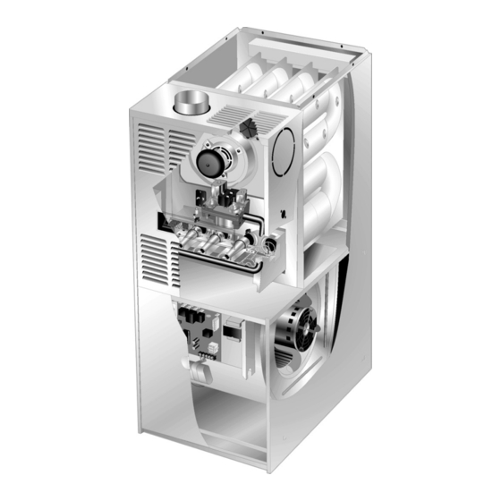
FILTER AIR RESITANCE HIGH ALTITUDE cfm (L/s) in. w.g. (Pa) All −1 to −14 models − Pressure regulator adjustment may be 0 (0) 0.00 (0) required depending on altitude. See below for proper pressure regulator setting. 200 (95) 0.01 (0) 400 (190) 0.03 (5) Manifold Pressure (Outlet) in. - Page 14 G40UH(X) PARTS ARRANGEMENT Air Deflector G40UH−48C−135, G40UH−36C−110, G40UH−60D−155 & G40UH−60C−110−1, −2, −3 Units Only Flue Box Gasket Heat Exchanger Gasket Pressure Port Location Flue Collector Box For −1 to −14 Units Flue Transition Combustion Air Orifice Combustion Air Prove Switch Pressure Port Combustion Air Inducer...
-
Page 15: Parts Identification
G40UH(X) PARTS IDENTIFICATION (HORIZONTAL POSITION) BLOWER ASSEMBLY SECONDARY LIMIT BLOWER ACCESS PANEL HEAT EXCHANGER ASSEMBLY PROVE CONTROL SWITCH BOARD BURNER ASSEMBLY COMBUSTION AIR BURNER INDUCER ACCESS PANEL PRIMARY LIMIT GAS VALVE FIGURE 2 Air Deflector G40UH(X) HEATING COMPONENTS G40UH−48C−135, G40UH−36C−110, G40UH−60D−155 &... -
Page 16: I Unit Components
3. SureLight Integrated Ignition Control return air and may be cut out in the field. (A92) 10M93 & 56L84 ELECTROSTATIC DISCHARGE (ESD) The Lennox SureLight ignition system consists of ignition Precautions and Procedures control (figure 5 with control terminal designations in table CAUTION 1), sensor (figure 10) and ignitor (figure 11). - Page 17 bustion air inducer is energized. When the differential in the SURELIGHT INTEGRATED CONTROL BOARD prove switch is great enough, the prove switch closes and a 15−second pre−purge begins. If the prove switch is not proven within 2−1/2 minutes, the control goes into Watch- guard−Pressure Switch mode for a 5−minute re−set period.
- Page 18 The ignition control is equipped with two LED lights for troubleshooting. The diagnostic codes are listed below in table 4. TABLE 4 DIAGNOSTIC CODES Make sure to Identify LED’S Correctly. Refer to figures 5 and 8 for control board layout. LED #2 LED #1 DS #1...
- Page 19 4. Integrated Ignition Control (A92) INTEGRATED IGNITION CONTROL 78M47 & 100973−01 WARNING Shock hazard. Disconnect power before servicing. Control is not field repairable. If control is inoperable, sim- ply replace entire control. Can cause injury or death. Unsafe operation will result if repair is attempted.
- Page 20 Electronic Ignition (See Figure 7) 5.Flame Sensor (Figure 10) On a call for heat the ignition board monitors the combus- A flame sensor is located on the left side of the burner sup- tion air inducer prove switch. The control board will not be- port.
- Page 21 Ignitor Location G40UH−15 and later assembly shown IGNITOR TYPE A" B" Combustion Air Inducer Silicon nitride .625 .406 90° 90° (Upflow Position) .685 .306 Mini Nitride MOUNTING SCREWS (Remove) MEASUREMENT IS TO I.D. A" OF RETENTION RING B" Flue Transition (Do not remove BRACKET BURNERS FRONT VIEW...
- Page 22 If flame rollout is detected, the gas valve will close and igni- limit switch must be replaced, refer to Lennox Repair Parts tion control will be disabled. Rollout can be caused by a handbook.
-
Page 23: Combustion Air Inducer
GAS VALVE ON/OFF SWITCH SHOWN IN ON POSITION lator adjustment screw is located on the valve. FIGURE 18 LPG changeover kits are available from Lennox. Kit s include 13.Combustion Air Inducer burner orifices and a gas valve regulator conversion kit. -
Page 24: Iii Start Up
TABLE 11 Turn knob on gas valve clockwise to OFF. Do not force. See figure 18. PROVE SWITCH SET POINTS White Rodgers 36E/36F Gas Valve − Move gas valve −1 to −14 0 − 4500ft 4501’ − 7500’ 7501’ − 10,000’ switch to OFF position. - Page 25 3 − After allowing unit to stabilize for 5 minutes, record Gas Leak Detector is strongly recommended. It is available manifold pressure. through Lennox under part number 31B2001. See Corp. 8411−L10, for further details. NOTE−Shut unit off and remove manometer as soon as an accurate reading has been obtained.
- Page 26 F− Proper Gas Flow (Approximate) TABLE 14 & Combustion G40UH Unit Range Nat Range LP Furnace should operate at least 5 minutes before check- 24A−045(X) 5.50 − 6.50 6.80 − 7.80 ing gas flow. Determine time in seconds for two revolu- tions of gas through the meter.
- Page 27 TRANSDUCER #78H5401 available from (PART #78H5401) NOTE− The following is a generalized procedure and Lennox Repair Parts) is does not apply to all thermostat controls. required to measure flame signal if meter used will not 1 − Blower operation is dependent on thermostat control read a low micro amp sig- system.
-
Page 28: Vi Maintenance
3 − With only the blower motor running and the evaporator G40UH(X) BURNER & HEAT coil dry, observe the manometer reading. Adjust blow- EXCHANGER REMOVAL er motor speed to deliver the air desired according to the job requirements. 4 − External static pressure drop must not be more than 0.5"... - Page 29 Replace all screws to the collector box and com- 1 − Check and clean blower wheel. bustion air inducer. Leaving off screws may cause 2 − Motors used on the Lennox G40UH(X) series units leaks. are permanently lubricated and need no further lu- 13−...
-
Page 30: Vii Wiring And Sequence Of Operation
VII− Wiring and Sequence of Operation 1 − When there is a call for heat, W1 of the thermostat en- 5 − Gas valve opens for a 4−second trial for ignition ergizes W of the furnace control with 24VAC. 6 − Flame is sensed, gas valve remains open for the heat 2 −... - Page 31 G40UH with Ignition Control 10M93 or 56L84 HEATING SEQUENCE OF OPERATION ABNORMAL HEATING MODE NORMAL HEATING MODE POWER ON GAS VALVE OFF. COMBUSTION AIR INDUCER OFF. INDOOR BLOWER DELAY OFF. CONTROL SELF−CHECK OKAY? LED #1 ON LED #2 ON (RESET CONTROL BY TURNING MAIN POWER OFF.) POLARITY REVERSED.
- Page 32 HEATING SEQUENCE OF OPERATION ABNORMAL HEATING MODE NORMAL HEATING MODE GAS VALVE OFF. COMBUSTION AIR INDUCER OFF. POWER ON INDOOR BLOWER DELAY OFF. LED #1 ON LED #2 ON CONTROL SELF−CHECK OKAY? (RESET CONTROL BY TURNING MAIN POWER OFF.) IS POLARITY REVERSED? POLARITY REVERSED.
- Page 33 HEATING SEQUENCE CONTINUED NORMAL HEATING MODE ABNORMAL HEATING MODE 15-SECOND COMBUSTION AIR INDUCER PREPURGE INITIATED BY CLOSED PROVE SWITCH. IS VOLTAGE ABOVE 75 VOLTS? LEDS SIGNAL IGNITOR WARM-UP −− 20 SECONDS. ALTERNATING IS THERE A PROPER GROUND? FAST FLASH 4-SECOND TRIAL FOR IGNITION. IS IGNITOR INTACT AND CONNECTED? GAS VALVE OPENS.
- Page 34 COOLING SEQUENCE OF OPERATION NORMAL COOLING MODE ABNORMAL COOLING MODE POWER ON IGNITION CONTROL MAIN POWER ON. GAS VALVE OFF. COMBUSTION AIR INDUCER OFF. INDOOR BLOWER OFF WITH NORMAL DELAY. CONTROL SELF DIAGNOSTIC CHECK. SIGNAL CIRCUIT BOARD FAILURE AT LED. IS CONTROL OPERATING NORMALLY? INTERRUPT MAIN POWER TO RESET CONTROL.
- Page 35 CONTINUOUS HEAT SPEED FAN SEQUENCE OF OPERATION LED: SLOW FLASH RATE REMAINS UNCHANGED THROUGHOUT SEQUENCE. MANUAL FAN SELECTION MADE AT THERMOSTAT. CONTROL (G) ENERGIZES SYSTEM FAN AT HEAT−H HEAT SPEED. EAC−H TERMINAL IS ENERGIZED. HUM−H TERM. ENERGIZES THERMOSTAT CALLS FOR HEAT (W). WITH COMB.
- Page 36 1 − When there is a call for heat, W1 of the thermostat energizes W of the furnace control with 24VAC. 2 − S10 primary limit switch, S47 rollout switch and S21 secondary limit are closed. Call for heat can continue. 3 −...
- Page 37 G40UH with Ignition Control 78M47 & 100973−01 LED#1 = AN1 LED#2 = AN2 HEATING SEQUENCE OF OPERATION ABNORMAL HEATING MODE NORMAL HEATING MODE POWER ON GAS VALVE OFF. COMBUSTION AIR INDUCER OFF. INDOOR BLOWER DELAY OFF. CONTROL SELF−CHECK OKAY? LED #1 ON LED #2 ON (RESET CONTROL BY TURNING MAIN POWER OFF.) POLARITY REVERSED.
- Page 38 HEATING SEQUENCE CONTINUED NORMAL HEATING MODE ABNORMAL HEATING MODE 15-SECOND COMBUSTION AIR INDUCER PREPURGE INITIATED BY CLOSED PRESSURE SWITCH. LEDS SIGNAL ALTERNATING FAST FLASH UNTIL IGNITOR WARM-UP −− 20 SECONDS. IS VOLTAGE ABOVE 90 VOLTS? VOLTAGE IS ABOVE 95 VOLTS, THEN RESTARTS HEATING 4-SECOND TRIAL FOR IGNITION.
- Page 39 COOLING SEQUENCE OF OPERATION NORMAL COOLING MODE ABNORMAL COOLING MODE POWER ON IGNITION CONTROL MAIN POWER ON. GAS VALVE OFF. COMBUSTION AIR INDUCER OFF. INDOOR BLOWER OFF WITH NORMAL DELAY. CONTROL SELF DIAGNOSTIC CHECK. SIGNAL CIRCUIT BOARD FAILURE AT LED. IS CONTROL OPERATING NORMALLY? INTERRUPT MAIN POWER TO RESET CONTROL.
- Page 40 CONTINUOUS HEAT SPEED FAN SEQUENCE OF OPERATION LED: SLOW FLASH RATE REMAINS UNCHANGED THROUGHOUT SEQUENCE. MANUAL FAN SELECTION MADE AT THERMOSTAT. CONTROL (G) ENERGIZES SYSTEM FAN AT HEAT SPEED. EAC TERMINAL IS ENERGIZED. HUM TERM. ENERGIZES THERMOSTAT CALLS FOR HEAT (W). WITH COMB.
-
Page 41: Trouble Shooting Guide
TROUBLE SHOOTING GUIDE UPON INITIAL POWER UP, REMOVE ALL THERMOSTAT DEMANDS TO THE UNIT PROBLEM: 1 UNIT FAILS TO OPERATE IN THE COOLING, HEATING, OR CONTINUOUS FAN MODE Condition Possible Cause Corrective Action / Comments 1.1.1 ACTION 1 − Check 120V main voltage. −... - Page 42 PROBLEM 1: UNIT FAILS TO OPERATE IN THE COOLING, HEATING, OR CONTINUOUS FAN MODE Condition Possible Cause Corrective Action / Comments ACTION 1 − Check that the unit is properly 1.5.1 ground. − Diagnostic lights flash the improper ACTION 2 − Install a proper main ground to the Improper ground to the unit.
- Page 43 PROBLEM 2: UNIT FAILS TO FIRE IN THE HEATING MODE, COMBUSTION AIR INDUCER DOES NOT ENERGIZE (CONT.). Condition Possible Cause Corrective Action/Comments − Unit operates with a cooling and con- 2.3.1 ACTION 1 − Check for correct wiring and loose tinuous fan demand.
- Page 44 PROBLEM 4: UNIT FAILS TO FIRE IN THE HEATING MODE, COMBUSTION AIR BLOWER ENERGIZES, IGNITOR IS ENERGIZED. Condition Possible Cause Corrective Action/Comments ACTION 1 − Check line pressure at the gas valve. 4.1.1 Pressure should not exceed 13" WC for both nat- −...
- Page 45 PROBLEM 5: BURNERS LIGHT WITH HEATING DEMAND BUT UNIT SHUTS DOWN PREMATURELY (CONT.) Condition Possible Cause Corrective Action/Comments ACTION 1 − Check that the manifold pressure matches value listed on nameplate. See installa- − Combustion air inducer energizes 5.3.1 tion instructions for proper procedure. with a heating demand.
- Page 46 PROBLEM 6: CONTROL SIGNALS LOW FLAME SENSE DURING HEATING MODE Condition Possible Cause Corrective Action/Comments 6.1.1 ACTION 1 − Check the sensor rod for proper loca- − Unit operates correctly but the diag- tion on the burner. Properly locate the sensor rod Sensor rod is improperly located on or replace if rod cannot be located correctly.