Table of Contents
Advertisement
Quick Links
Repair - Parts
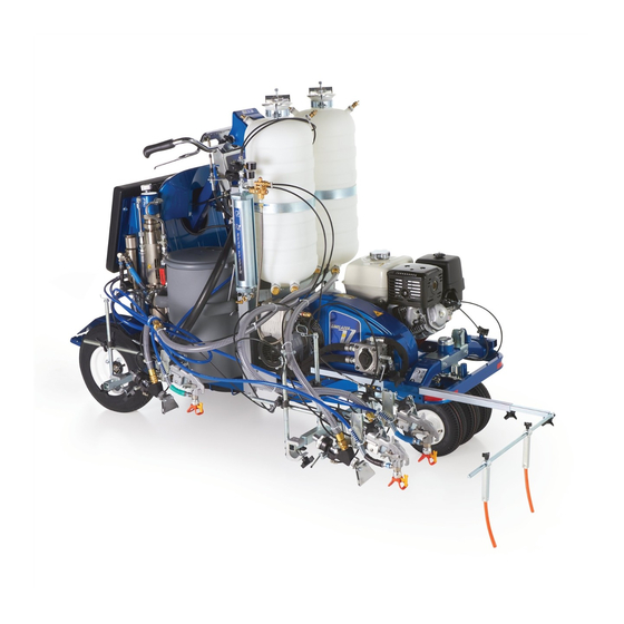
LineLazer V 250
Self-Propelled Line Striper
For the application of line striping materials.
For professional use only. For outdoor use only.
Not for use in explosive atmospheres or hazardous locations.
Maximum Operating Speed: 10 mph (16 kph)
Maximum Operating Pressure: 3300 psi (22.8 MPa, 228 bar)
IMPORTANT SAFETY INSTRUCTIONS
Read all warnings and instructions in this manual and in related manuals.
Be familiar with the controls and the proper usage of the equipment.
Save these instructions.
Pressurized
Model
Guns
Bead System
17H471
2
No
17H472
3
No
17H473
2
Yes - 2 Tank
25P365
2
Yes - 2 Tank
17H474
3
Yes - 2 Tank
17H466
1
No
17H467
2
No
17H468
1
Yes - 1 Tank
17J951
2
Yes - 1 Tank
17H469
2
Yes - 2 Tank
Related Manuals:
3A3393
Operation
311254
Gun
309277
Pump
3A3428
Auto-Layout Applications Methods
332230
Pressurized Bead System (PBS)
3A6981
Steering Cable Replacement
Use only genuine Graco replacement parts.
The use of non-Graco replacement parts may void warranty.
and 250
SPS
Description
LLV 250
DC
LLV 250
DC
LLV 250
DC
LLV 250
DC
LLV 250
DC
LLV 250
SPS
LLV 250
SPS
LLV 250
SPS
LLV 250
SPS
LLV 250
SPS
ti23089a
DC
3A3394E
EN
Advertisement
Table of Contents

Related Manuals for Graco LineLazer V 250SPS


Summary of Contents for Graco LineLazer V 250SPS
- Page 1 Yes - 2 Tank LLV 250 Related Manuals: 3A3393 Operation 311254 309277 Pump 3A3428 Auto-Layout Applications Methods 332230 Pressurized Bead System (PBS) 3A6981 Steering Cable Replacement ti23089a Use only genuine Graco replacement parts. The use of non-Graco replacement parts may void warranty.
-
Page 2: Table Of Contents
Removal ......35 Graco Standard Warranty ....72 Installation . -
Page 3: Warnings
• Check hoses and parts for signs of damage. Replace any damaged hoses or parts. • This system is capable of producing 3300 psi. Use Graco replacement parts or accessories that are rated a minimum of 3300 psi. • Always engage the trigger lock when not spraying. Verify the trigger lock is functioning properly. - Page 4 Warnings CARBON MONOXIDE HAZARD Exhaust contains poisonous carbon monoxide, which is colorless and odorless. Breathing carbon monoxide can cause death. • Do not operate in an enclosed area. EQUIPMENT MISUSE HAZARD Misuse can cause death or serious injury. • Do not operate the unit when fatigued or under the influence of drugs or alcohol. •...
- Page 5 Warnings TOXIC FLUID OR FUMES HAZARD Toxic fluids or fumes can cause serious injury or death if splashed in the eyes or on skin, inhaled, or swal- lowed. • Read Safety Data Sheet (SDS) to know the specific hazards of the fluids you are using. •...
- Page 6 Warnings Important Laser Information for Units with Laser Option LASER LIGHT HAZARD: AVOID DIRECT EYE CONTACT Eye exposure to Class IIIa/3R levels of laser light can potentially present an eye (retinal) injury hazard, includ- ing spot blindness or other retinal injury. To avoid direct eye exposure: •...
- Page 7 Warnings Battery Disposal Do not place batteries in the trash. Recycle batteries according to local regulations. To find a recycling location in the USA and Canada call 1-800-822-8837 or go to www.call2recycle.org. ti25930a 3A3394E Repair - Parts...
-
Page 8: Component Identification (Llv 250Dc Shown)
Component Identification (LLV 250DC Shown) Component Identification (LLV 250 Shown) 10 Serial label under operator platform Paint filter, both sides 11 Rear gun arm mount, both sides Adjustable pad 12 Hydraulic fill cap/dipstick Engine fuel cap 13 Prime/drain valve, both sides Wheel motor bypass valve 14 Handle bar height adjustment knob Straight line adjuster... -
Page 9: Component Identification (Controls)
Component Identification (Controls) Component Identification (Controls) ti23143a 12V accessory jack Gun trigger control Engine key switch, OFF - ON - Start Gun 1, 2, 3 selector Engine clutch switch Display 10 Engine choke Forward/reverse lever 11 Engine throttle Pressure control Hydraulic pump valve, both sides 3A3394E Repair - Parts... -
Page 10: Grounding Procedure (For Flammable Materials Only)
Grounding Procedure (For Flammable Materials Only) Grounding Procedure 2. Set pump valve(s) to OFF (250 has one pump valve; 250 has two pump valves). Turn engine OFF. (For Flammable Materials Only) This equipment must be grounded to reduce the risk of static sparking. -
Page 11: Ground Drive Belt Replacement
Ground Drive Belt Replacement Ground Drive Belt Installation Replacement 1. Install belt onto pulleys. Removal ti19134a 1. If equipped with a Pressurized Bead System, 2. Tighten tensioning bolt to move two pulleys apart remove pressurized bead tanks and compressor, and tighten belt to proper tension (see table). see Pressurized Bead System manual 332230. -
Page 12: Oil Reservoir Belt Replacement
Oil Reservoir Belt Replacement Oil Reservoir Belt Installation Replacement 1. Replace belt. ti19149a Removal 2. Tighten two adjustment bolts evenly and maintain NOTE: Ground drive belt must be removed before oil belt alignment. Tighten belt to proper tension (see table). reservoir belt can be replaced, see Ground Drive Belt Replacement, page 11. -
Page 13: Hydraulic System Purging
Hydraulic System Purging Hydraulic System 5. Start engine and run at low speed. Purging This equipment stays pressurized until pressure is manually relieved. To help prevent serious injury from pressurized fluid, such as skin injection, splashing fluid and moving parts, follow the Pressure Relief ti23889a Procedure when you stop dispensing and before 6. - Page 14 Hydraulic System Purging 8. Turn the prime valve down and open the hydraulic 9. Repeat step 8 for the other pump. pump valve. Allow the paint pump to stroke 10 times 10. The hydraulic gun manifold is self-purging. and then close the hydraulic pump valve. 11.
-
Page 15: Ground Drive Pump Replacement
Ground Drive Pump Replacement Ground Drive Pump 5. Disconnect all fittings and hoses from pump (63). Replacement NOTE: Oil will spill out of hoses. Have rags and waste pail nearby. 6. Remove nut (3) and disconnect tie rod (40) under- neath pump (63). -
Page 16: Oil Reservoir Pump Replacement
Oil Reservoir Pump Replacement Oil Reservoir Pump 5. Loosen two set screws and cable. Replacement ti19142a 6. Remove eight screws and oil reservoir cover with pump. This equipment stays pressurized until pressure is manually relieved. To help prevent serious injury from pressurized fluid, such as skin injection, splashing fluid and moving parts, follow the Pressure Relief Procedure when you stop dispensing and before... -
Page 17: Installation
Oil Reservoir Pump Replacement Installation 3. Install pulley on pump shaft and maintain belt align- ment to inner groove of the clutch pulley. Tighten two pulley screws. 1. Install pump onto oil reservoir cover with four screws. Make sure the five o-rings are in place. ti19670a ti19671a 4. - Page 18 Oil Reservoir Pump Replacement 6. Install cable and tighten two set screws. 8. Connect five hydraulic hoses to fittings on oil reservoir. Replace oil filter. ti19143b 7. Slide cable sleeve up and tighten screw. ti19145a ti23901a 9. Install and tension belts, see Oil Reservoir Belt Replacement, page 12 and Ground Drive Belt Replacement, page 11.
-
Page 19: Hydraulic Gun Manifold Replacement
Hydraulic Gun Manifold Replacement Hydraulic Gun Manifold Replacement ti19164a Removal 1. Remove tank lid(s) and siphon tube(s). 5. Label wire harnesses GUN 1, GUN 2, and GUN 3. Disconnect three wire harnesses from solenoids. Gun 3 Gun 2 Gun 1 LL250 shown 2. -
Page 20: Installation
Hydraulic Gun Manifold Replacement Installation 7. Use a needle-nose pliers to remove gun cables from bracket. 1. Slide hydraulic manifold in and up into unit. Install and tighten two mounting bolts. ti23911a 8. Use wrench to disconnect manifold tubes by the paint pump. - Page 21 Hydraulic Gun Manifold Replacement 4. Observe label on bracket. Push labeled gun cables 6. Connect three wire harnesses to solenoids. into manifold brackets. Gun 3 Gun 2 Gun 1 ti23916a 7. Install pad and tighten four screws. 8. Install front shield to unit and tighten six screws. ti23964a 5.
-
Page 22: Paint Pump Replacement
Paint Pump Replacement Paint Pump Replacement This equipment stays pressurized until pressure is manually relieved. To help prevent serious injury from pressurized fluid, such as skin injection, splashing fluid and moving parts, follow the Pressure Relief Procedure when you stop dispensing and before cleaning, checking, or servicing the equipment. -
Page 23: Hydraulic Motor Replacement
Hydraulic Motor Replacement Hydraulic Motor Installation Replacement 1. Install hydraulic motor with four mounting bolts (116). NOTICE Use a screwdriver to lift pump piston up to gain access to mounting bolts and avoid contact with piston. Con- tact with pump mounting bolts can scratch and damage the pump piston. -
Page 24: Clutch Replacement
Clutch Replacement Clutch Replacement 6. Remove three bolts (81) and pulley (61). Removal 1. Remove ground drive belt, page Ground Drive Belt Replacement, page 11. ti19216a 7. Remove engine recoil starter and place a screw- 2. Remove oil reservoir belt, see Oil Reservoir Belt driver through the recoil starter cup. -
Page 25: Installation
Clutch Replacement 9. Disconnect clutch connector to main wire harness. ti19692a ti19212a 4. Install pulley (61) and torque three screws (81) to 10 Installation ft-lb (13 N•m). 1. Install spacer (56) and key (60) onto crankshaft. Slide clutch (57) onto crankshaft. ti19216a 5. - Page 26 Clutch Replacement 6. Connect clutch to wire harness. 7. Install ground drive pump assembly with tensioning and two hold-down bolts. ti19908a ti19212a 8. Install and tension belts, see Oil Reservoir Belt Replacement, page 12 and Ground Drive Belt Replacement, page 11. 3A3394E Repair - Parts...
-
Page 27: Engine Replacement
Engine Replacement Engine Replacement 5. Disconnect throttle cable. Removal 1. Remove clutch, see Clutch Replacement, page 24. ti19183a NOTICE 6. Disconnect choke cable. To reduce the risk of battery damage and shorts, always disconnect NEGATIVE (black wire) first. 2. Disconnect two negative (black) battery wires at bat- tery. -
Page 28: Installation
Engine Replacement Installation 4. Install throttle cable. a. Place speed lever to high speed. 1. Install engine voltage regulator below engine b. Insert “Z” bend wire into hole furthest from pivot. mounting plate with two screws. Connect regulator to wire harness. c. -
Page 29: Touch-Pad Display
Touch-Pad Display Touch-Pad Display ti23924a NOTICE To avoid electrostatic-discharge (ESD) always use wrist strap 112190 when servicing the touch-pad display. 1. Toggle switch kit. a. Torque screws to 3-5 in-lb (0.34-0.56 N•m) b. Torque nuts to 3-5 in-lb (0.34-0.56 N•m) 2. -
Page 30: Control Board Replacement
Control Board Replacement Control Board 5. Remove four screws and remove pad. Replacement Removal 1. To disconnect power remove fuse, see Fuse Replacement, page 34. 2. Remove siphon tube(s) and lid(s). ti23930a 6. Remove six screws and control shroud. LL250 Shown 3. -
Page 31: Installation
Control Board Replacement 7. Remove two screws and splash shield. 3. Connect all wires to control board. See, Wiring Dia- gram, page 68. Pump number 1 is on the left when you stand in the operator position. 4. Bundle and secure wires with a cable tie just inboard of the choke cable. - Page 32 Control Board Replacement 10. Install front shield and tighten six screws. 11. Install tank(s), lid(s) and siphon tube(s). ti19200a 12. If control board was replaced select language, units, and calibrate distance sensor (see Operation manual). 3A3394E Repair - Parts...
-
Page 33: Battery Replacement
Battery Replacement Battery Replacement Installation NOTICE To reduce the risk of battery damage and shorts, always connect NEGATIVE (black wire) last. Removal 1. Place battery on operator platform. Connect two red wires to positive (+) post of the battery. 1. Battery may be removed from the back of the unit by sliding it out above the operator platform. -
Page 34: Fuse Replacement
Fuse Replacement Fuse Replacement 1. Remove fuse cover. 4. Use needle-nose pliers to install new fuse. 2. Use needle-nose pliers to remove old fuse and 5. Replace cover. inspect it for an open circuit. 3. If fuse is open, a wire has shorted to the frame or aux- iliary lighting requires too much power. -
Page 35: Forward/Reverse Cable Replacement
Forward/Reverse Cable Replacement Forward/Reverse Cable Replacement Removal 1. If equipped with a Pressurized Bead System, remove pressurized bead tanks and compressor. ti19128a See Pressurized Bead System manual 332230. 6. At the handlebar, remove locknut (3) and ball joint 2. Remove tank lids and siphon tubes. (40) from handlebar forward/reverse lever. -
Page 36: Installation
Forward/Reverse Cable Replacement Installation 4. Verify that the handlebar forward/reverse lever does not touch handlebar grips. Adjust cable and ball joints if needed. 1. Install new cable (148) by following same route as old cable is being removed. 5. Install belt cover and tighten four screws. 2. -
Page 37: Steering Cable Replacement
Steering Cable Replacement Steering Cable Replacement Removal 2. Remove six screws and control shroud. 1. Loosen four screws and remove pad. ti23930a ti23931a 3A3394E Repair - Parts... - Page 38 Steering Cable Replacement 3. Apply parking brake. Raise front wheel off the 5. On front wheel fork, remove locknut (3) and ball joint ground and support frame on two jack stands. (40) from fork. Remove ball joint (40) from cable (48) and save if not replacing.
-
Page 39: Installation
Steering Cable Replacement Installation 5. Install ball joint (40) onto cable (48) and match threads on other side of handlebar. Install ball joint (40) into handlebar and tighten locknut (3). 1. Install new cable (48) by following same route as old cable is being removed. -
Page 40: Front Wheel Replacement
Front Wheel Replacement Front Wheel Replacement Removal Installation 1. Apply parking brake. Raise front wheel off ground 1. Insert two spacers (36) into wheel (35) and slide into and support frame on two jack stands. fork (34). ti19693a ti20125a 2. Remove locknut (39) from axle bolt (37) and remove axle bolt (37) from fork (34). -
Page 41: Parking Brake Service
Parking Brake Service Parking Brake Service Removal Installation 1. Remove tire, wheel hub, and fender. See, Wheel 1. Install lever (14) with pin (B) and clip (13). Motor Removal, page 42. 2. Use screwdriver to install spring (15). 2. Remove clips (13) from three pins (A). Remove pins 3. -
Page 42: Rear Wheel And Wheel Motors
2. Remove four lug nuts (22) and wheel (16). ti18589a 3. Remove pin (56), castle nut (21b) and wheel hub (22b). Wheel hub may require a wheel puller; not supplied by Graco. ti18589a Rear Wheel Installation 1. Replace wheel and install lug nuts. Alternately tighten lug nuts opposite of each other. -
Page 43: Wheel Motor Installation
Rear Wheel and Wheel Motors Wheel Motor Installation 1. Connect two hydraulic hoses (112) to wheel motor (21a) and insert wheel motor (21a) into frame (1). 2. Install wheel motor (21a) and fender (19) with four bolts (78) and lock nuts (79). 3. - Page 44 Rear Wheel and Wheel Motors ti18564a ti19329a NOTE: Sensor is working properly if the measure display reads 12.3 to 12.7 ft (3.75 to 3.87 m). 5. Install wheel (16) and four lug nuts (22). ti23946a Installation ti18589a 1. Install wheel sensor (4) and clamp (5) with screw 6.
-
Page 45: Troubleshooting
Troubleshooting Troubleshooting General Problem Cause Solution Turn key switch to ON. Choke engine and pull recoil Battery is discharged. starter rope. Engine will not crank Key switch is defective. Replace key switch. Main wire harness is defective. Replace wire harness, see Wiring Diagram, page 68. Excessive hydraulic load. - Page 46 Change hydraulic filter and hydraulic oil. Intake line to pump inlet is not tight. Tighten intake line to pump inlet. Hydraulic motor is worn or damaged. Bring sprayer to Graco distributor for repair. Suction tube strainer is clogged. Clean strainer Suction tube air leak.
- Page 47 Troubleshooting Problem Cause Solution Remove throat packing nut spacer. Tighten throat Throat packing nut is loose. packing nut just enough to stop leakage. Excessive paint leakage into throat packing nut Throat packings are worn or damaged. Replace packings. See Pump manual. Displacement rod is worn or damaged.
- Page 48 Dot size setting is too small Increase dot size. Pressure is too low Increase pressure to 1000 psi. Use only Graco approved hydraulic fluid 169236 (5 gallons / 18.9 liter) or 207428 (1 gallon / 3.8 liter) 3A3394E Repair - Parts...
-
Page 49: Notes
Notes Notes 3A3394E Repair - Parts... -
Page 50: Parts
Parts Parts 189b 189a *102 *179 189c *100 55 *179 *LLV 250DC only ti23185c 3A3394E Repair - Parts... -
Page 51: Parts List
Parts Parts List Ref. Part Description Qty. Ref. Part Description Qty. 189c 24V560 KIT, repair, actuator, piston 260212 SCREW, hex washer hd, thd form (includes 234, 235, 236, 334, 335, 16M279 BUMPER, platform 336) 100101 SCREW, cap, hex hd 16W373 BRACKET, manifold, hydraulic, 101566 NUT, lock 111145 KNOB, pronged 116829 FITTING, 90 degree... -
Page 52: Parts
Parts Parts 25 34 29 22 (See Page 8) ti23186a 3A3394E Repair - Parts... -
Page 53: Parts List
Parts Parts List Ref. Part Description Qty. Ref. Part Description Qty. 24M196 HANDLE, control, forward/reverse 102393 NUT, lock 112798 SCREW, thread forming, hex hd 116424 NUT 119532 BEARING, flanged 100022 SCREW, cap, hex hd 15E780 PIN, fork 102040 NUT, lock 15K162 BLOCK 115480 KNOB, T-handle 16N401 SWITCH, push button... -
Page 54: Parts (24U235 Control Panel)
Parts (24U235 Control Panel) Parts (24U235 Control Panel) ti23976a 3A3394E Repair - Parts... -
Page 55: Parts List
Parts (24U235 Control Panel) Parts List Ref. Part Description Qty. Ref. Part Description Qty. 17C064 WIRE, positive 16X077 PLATE, control, LL250 152 16Y411 BUSHING, pressure control mount 24V561 KIT, repair, control board (includes 153 119775 NUT, panel 154 24V563 SHAFT, flexible 16X074 LABEL 156 115999 RING, retaining 17C063 SWITCH, rocker, SPST... -
Page 56: Parts
Parts Parts ti19069b 3A3394E Repair - Parts... -
Page 57: Parts List
16X126 LABEL, brand, LineLazer, DC, 24N499 KIT, repair, bracket, hydro pump side (includes 75, 76, 77, 242) 189892 LABEL, Graco logo 247930 KIT, repair, hydraulic pump 241 194126 LABEL, warning 16M078 PULLEY, 5 o.d. x 15mm 242 16M768 LABEL, pinch hazard iso... -
Page 58: Parts
Parts Parts 292 290 246 284 174* 174** * LLV 250DC **LLV 250SPS ti28184a 3A3394E Repair - Parts... -
Page 59: Parts List
Parts Parts List Ref. Part Description Qty. Ref. Part Description Qty. 101754 PLUG, pipe 111145 KNOB, pronged 120604 GASKET, reservoir 125794 SCREW, taptite, hex washer hd 24K967 TUBE, supply, hydraulic 181072 KIT, repair, strainer 116919 FILTER 16X081 BRACKET, dual tank retaining 15E587 TUBE, suction 126108 SCREW, shoulder, socket head 154594 PACKING, o-ring... -
Page 60: Parts (Front Wheel)
Parts (Front Wheel) Parts (Front Wheel) Series A Series B ti19066b ti27030a 3A3394E Repair - Parts... -
Page 61: Parts List - Series A
Parts (Front Wheel) Parts List - Series A Parts List - Series B Ref. Part Description Qty. Ref. Part Description Qty. 24L896 FRAME, painted, LL250 24L896 FRAME, painted, LL250 102393 NUT, lock 102393 NUT, lock 15V264 SPRING, extension 113743 SCREW, cap, hex hd 113743 SCREW, cap, hex hd 24L902 ADJUSTER, caster, weldment, LL250... -
Page 62: Parts (Gun Mount)
Parts (Gun Mount) Parts (Gun Mount) 172j 172c 229a 172b 172d 172f 229b 229c 172m 172n 172g 172a 172k 172h ti28185b 3A3394E Repair - Parts... -
Page 63: Parts List
Parts (Gun Mount) Parts List Ref. Part Description Qty. Ref. Part Description Qty. 172b 16M850 BRACKET, cable, gun, 111040 NUT, lock, insert, nylock, 5/16 172c 17J145 ARM, holder, gun 24N170 BRACKET, mount, pointer 172d 119647 SCREW, cap, socket, flthd complete 172f 15F750 KNOB, holder, gun 24N171 ARM, pointer, complete... -
Page 64: Parts
Parts Parts 2ref ti19068b 3A3394E Repair - Parts... -
Page 65: Parts List
Parts Parts List Ref. Part Description Qty. Ref. Part Description Qty. 114766 BOLT, cap hex head 125929 MOTOR, wheel 801020 NUT, lock, hex 15K357 SENSOR, distance 16M271 HOSE, coupled, assembly, LL250 108868 CLAMP, wire 24N508 KIT, repair, hub and gear assy 260212 SCREW, hex washer hd, thd form 245340... -
Page 66: Parts (Pump)
Parts (Pump) Parts (Pump) ti19074b 3A3394E Repair - Parts... -
Page 67: Parts List (Pump)
379* 117285 PACKING, o-ring 102040 NUT, lock, hex 380* 287285 KIT, repair, filter cap 117 15H108 LABEL, pinch point (includes 378, 379) 15B804 LABEL, Graco logo 384* 193710 SEAL, seat, valve 119 15B063 LABEL 385* 193709 SEAT, valve 24V064 KIT, repair, suction hose 386* 245103 KIT, repair, drain valve 191239 HOSE, coupled, 3/8 in. -
Page 68: Wiring Diagram
Wiring Diagram Wiring Diagram ti23961b 3A3394E Repair - Parts... -
Page 69: Wiring Parts List
Wiring Diagram Wiring Parts List Ref. Part Description Qty. Ref. Part Description Qty. 189a 24N577 COIL, solenoid, hydraulic, manifold 15K357 SENSOR, distance (included in 189) 24V562 KIT, repair, engine, GX390 214b 24V561 KIT, repair, control board (includes 54a) 17C063 SWITCH, rocker, SPST 25P364 KIT, repair, engine, GX390 16X075 SWITCH, ignition (includes 54a) (China only) -
Page 70: Hydraulic Diagram
Hydraulic Diagram Hydraulic Diagram ti23962b 3A3394E Repair - Parts... -
Page 71: Hydraulic Parts List
Hydraulic Diagram Hydraulic Parts List Ref. Part Description Qty. Ref. Part Description Qty. 124941 FITTING, long elbow, hydraulic 125929 MOTOR, wheel 116829 FITTING, 90 degree, w/adjustable 16M271 HOSE, coupled, assembly, LL250 24M625 TUBE, supply, hydraulic 247930 KIT, repair, hydraulic pump 24M626 TUBE, supply, hydraulic 16X838 HOSE, hydraulic, supply 2nd pump 126082 FITTING, tee, #8 x #8 x #6 JIC... -
Page 72: Graco Standard Warranty
With the exception of any special, extended, or limited warranty published by Graco, Graco will, for a period of twelve months from the date of sale, repair or replace any part of the equipment determined by Graco to be defective.