Table of Contents
Advertisement
Quick Links
Operation, Repair, Parts
™
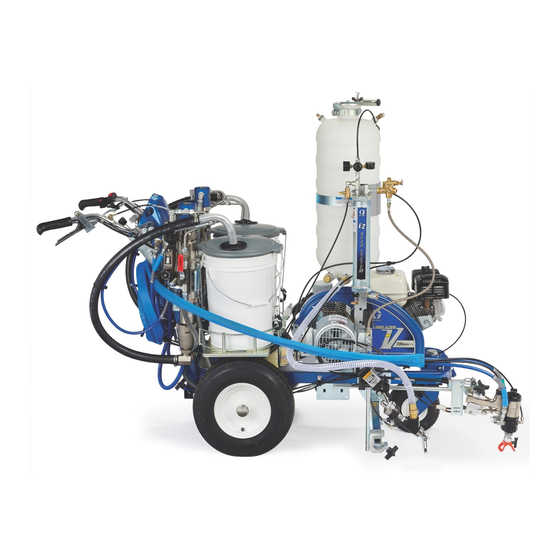
LineLazer
V 200MMA 1:1 Airless Line Stripers
For the application of two component line striping materials.
For professional use only.
For outdoor use only.
Not for use in explosive atmospheres or hazardous locations.
Maximum Operating Pressure: 3300 psi (22.8 MPa, 228 bar)
Important Safety Instructions
Read all warnings and instructions in this manual and in related manuals before using the equipment.
Be familiar with the controls and the proper usage of the equipment.
Save these instructions.
Important Medical Information
Read the medical alert card provided with the gun. It contains injection injury treatment information
for a doctor. Keep it with you when operating the equipment.
Related Manuals:
309277
Pump
3A3428
Auto-Layout Applications Methods
332230
Pressurized Bead System
Model:
HP Reflective
1 Auto Gun
1 PBS Tank
17Y234
17Y271
with laser
17Y513
17Y512
All auto guns can be actuated manually.
Use only genuine Graco replacement parts.
The use of non-Graco replacement parts may void warranty.
HP Reflective
2 Auto Guns
1 PBS Tank
with laser
3A6466A
EN
Advertisement
Table of Contents
Troubleshooting

Related Manuals for Graco LineLazer V 200MMA


Summary of Contents for Graco LineLazer V 200MMA
- Page 1 1 PBS Tank 1 PBS Tank 17Y234 17Y271 with laser 17Y513 17Y512 with laser All auto guns can be actuated manually. Use only genuine Graco replacement parts. The use of non-Graco replacement parts may void warranty.
-
Page 2: Table Of Contents
Keep Components A and B Separate ....15 LineLazer V 200MMA 1:1 ......65 Changing Materials . -
Page 3: Warnings
• Check hoses and parts for signs of damage. Replace any damaged hoses or parts. • This system is capable of producing 3300 psi. Use Graco replacement parts or accessories that are rated a minimum of 3300 psi. • Always engage the piston safety lock when not spraying. Verify the piston safety lock is functioning properly. - Page 4 Warnings CARBON MONOXIDE HAZARD Exhaust contains poisonous carbon monoxide, which is colorless and odorless. Breathing carbon monoxide can cause death. • Do not operate in an enclosed area. EQUIPMENT MISUSE HAZARD Misuse can cause death or serious injury. • Do not operate the unit when fatigued or under the influence of drugs or alcohol. •...
- Page 5 Warnings TOXIC FLUID OR FUMES HAZARD Toxic fluids or fumes can cause serious injury or death if splashed in the eyes or on skin, inhaled, or swal- lowed. • Read Safety Data Sheets (SDSs) to know the specific hazards of the fluids you are using. •...
-
Page 6: Battery Disposal
Warnings Important Laser Information for Units with Laser Option LASER LIGHT HAZARD: AVOID DIRECT EYE CONTACT Eye exposure to Class IIIa3/3R levels of laser light can potentially present an eye (retinal) injury hazard, including spot blindness or other retinal injury. To avoid direct eye exposure: •... -
Page 7: Tip Selection
Tip Selection Tip Selection (cm) (cm) (cm) (cm) 286321 3-4 (7-10) 286323 3-4 (7-10) 286325 3-4 (7-10) 286327 3-4 (7-10) 286331 3-4 (7-10) 286423 4-5 (10-13) 286425 4-5 (10-13) 286427 4-5 (10-13) 286429 4-5 (10-13) ... -
Page 8: Component Identification - Llv 200Mma
Component Identification - LLV 200MMA Component Identification - LLV 200MMA 11 Engine STOP Display 12 12 Volt Battery Spray Gun Control 13 Gun Actuator Prime/Spray Valve 14 Layout Laser Filter Manifold 15 Engine Kill Switch Piston Safety Lock 16 Identification Label Engine/Controls 17 A side Fluid Pump Drain and Siphon Tubes... -
Page 9: Component Identification - Gun
Component Identification - Fusion Gun Component Identification - Fusion Gun 10 Piston Safety Lock 1 A Side Fluid Valve 11 Gun Fluid Manifold B Side Fluid Valve 12 Mix Chamber Nozzle Spray Tip Adapter 13 Fluid Inlets (optional) (A Side Shown) 1/4”... -
Page 10: Piston Safety Lock
Piston Safety Lock Piston Safety Lock Loss of Air Pressure Engage piston safety lock whenever you are handling In event of loss of air pressure, gun will continue to the gun out of the holder and the gun is under pressure, spray. -
Page 11: Theory Of Operation
Theory of Gun Operation Theory of Gun Operation Gun Triggered (Fluid Spraying) Gun Detriggered (Air Purging) Mix chamber (19) moves back, shutting off purge air Mix chamber (19) moves forward, shutting off fluid flow. flow. Impingement ports (IP) align with fluid ports of side Impingement ports (IP) open to air chamber (AC), allow- seals (18c), allowing fluid to flow through mix chamber ing purge air to flow through mix chamber nozzle (N). -
Page 12: Grounding Procedure (For Flammable Flushing Fluids Only)
Grounding Procedure (For Flammable Flushing Fluids Only) Grounding Procedure 1. Perform Grounding Procedure (For Flammable Flushing Fluids Only), page 12. (For Flammable Flushing Fluids 2. Set both pump ON/OFF valves to OFF. Only) This equipment must be grounded to reduce the risk of static sparking. -
Page 13: Setup/Startup
Setup/Startup Setup/Startup 5. Fill fuel tank. 1. Perform Pressure Relief Procedure, page 12. 2. Perform Grounding Procedure (For Flammable ti27611a Flushing Fluids Only), page 12, if using flammable 6. Set A and B side pump ON/OFF valves to OFF. Set materials. - Page 14 Setup/Startup 8. Turn both prime valves to prime. Turn pressure con- d. Set engine switch to ON. trol counterclockwise to lowest pressure. ti27619a ti28015a e. Pull starter cord. NOTE: Minimum hose size allowable for proper sprayer operation is 3/8 in. x 11 feet & 1/4 in. x 7 feet for LLV 200MMA.
- Page 15 Setup/Startup 12. Digital display is functional after engine starts. 17. Turn pressure down, turn prime valve to spray. 18. Return drain line to component B pail. 19. Engage piston safety lock. 13. Mix BPO catalyst with component B per manufac- turer’s recommendation.
- Page 16 Setup/Startup 22. Hold gun against a grounded metal flushing pail. 27. Insert SwitchTip in tip bore and firmly thread Trigger gun and increase fluid pressure slowly until assembly onto gun. pump runs smoothly. 28. Test spray onto cardboard. Adjust pressure to achieve desired results.
-
Page 17: Keep Components A And B Separate
Setup/Startup Keep Components A and B Changing Materials Separate NOTICE Changing the material types used in your equipment requires special attention to avoid equipment damage and downtime. Cross-contamination can result in cured material in • When changing materials, flush the equipment fluid lines which could cause serious injury or dam- multiple times to ensure it is thoroughly clean. -
Page 18: Gun Placement
Gun Placement Gun Placement Install Guns NOTE: When striping above a curb, the mounting clamp can be rotated for clearance. 1. If pressurized, perform Pressure Relief Procedure, page 12. 2. Insert guns into gun holder. Tighten clamps. ti28129a Manual Guns Selection 4. -
Page 19: Auto Guns Selection
Gun Placement Auto Guns Selection 1. Use the gun selector buttons to determine which 2. Use the gun trigger control to actuate guns. guns are active. Each gun selector has 3 settings: continuous line, OFF, and programmed line pattern. ti27881a ti27784a 4 Examples: ti27785a... -
Page 20: Gun Positions Chart
Gun Placement Gun Positions Chart One line One line up to 24 in. (61cm) wide Two lines One line or two lines to spray around obstacles One gun curb Two gun curb Two lines or one line up to 24 in. (61 cm) wide 3A6466A Operation, Repair, Parts... -
Page 21: Gun Arm Mounts
Gun Placement Gun Arm Mounts 4. Tighten gun arm knob into gun arm mounting slot. This unit is equipped with front and rear gun arm mounts to allow the operator to place the guns in the optimal location. ti27798a NOTICE Make sure all hoses, cables, and wires are properly routed through brackets and do NOT rub on tire. -
Page 22: Installation
Gun Placement Installation No fluid spray 2. Turn screw in handle clockwise if spray icon 1. Install vertical gun mount onto gun bar. appears before fluid spray starts. ti27802a No spray icon NOTE: Make sure all hoses, cables, and wires are properly routed through brackets. -
Page 23: Gun Cable Adjustment
Gun Placement Gun Cable Adjustment 3. Insert plastic cable retainer into cable bracket hole. Adjusting the gun cable will increase or decrease the gap between the trigger plate and the gun trigger. To adjust trigger gap, perform the steps below. Manual Guns ti27806a 4. -
Page 24: Straight Line Adjustment
Gun Placement Straight Line Adjustment 4. Roll the striper. Repeat steps 2 and 3 until striper rolls straight. Tighten bolt on wheel alignment plate to lock the new wheel setting. The front wheel is set to center the unit and allows the operator to form straight lines. -
Page 25: Dot Laser
Gun Placement Dot Laser 4. Route wires from the switch to the battery and con- nect to the (+) and (-) terminals. LASER LIGHT HAZARD. Avoid direct eye contact. 1. Remove battery cover. ti27818a 5. Connect the switch leads to the wire harness. 6. -
Page 26: Cleanup
Cleanup Cleanup 4. Place B side siphon tube set in grounded metal pail partially filled with acetone. Attach ground wire to true earth ground. 5. Set B side pump valve to ON (pump is now active). 1. Perform Pressure Relief Procedure, page 12. 2. - Page 27 Cleanup 10. Open B fluid valve (about three full turns). 14. Clean mixing chamber, tip, and tip guard in acetone fluid. TI3375A FLUSH 15. Fill pump with Pump Armor and reassemble filter, guard and tip. 11. Disengage piston safety lock. 16.
-
Page 28: For Overnight Shutdown
(N), coating all surfaces. 2. Leave purge air valve turned on and gun detrig- Use Graco 117773 Grease, see page 87. gered while machine is still running. NOTE: Flow paths are not shown to scale, for clarity. -
Page 29: Linelazer V Livelook Display
LineLazer V LiveLook Display LineLazer V LiveLook Display HP Auto Series 3A6466A Operation, Repair, Parts... -
Page 30: Initial Setup (Hp Auto Series)
LineLazer V LiveLook Display Initial Setup (HP Auto Series) US Units Pressure = psi Volume = gallons The initial setup prepares the striper for operation based Distance = feet on a number of user entered parameters. Language Line Thickness = mil selections and the units of measure selections can be SI Units set before you start or changed later. - Page 31 LineLazer V LiveLook Display 6. Press and release gun trigger control to start cali- 3. Press to select Setup/Information. bration. CALIBRATION SETTINGS ti27912a INFORMATION ENG SPA FRE DEU RUS WORLD 7. Move striper forward. Keep laser dot on steel tape. LAYOUT MODE 8.
-
Page 32: Striping Mode (Hp Auto Series)
LineLazer V LiveLook Display Striping Mode (HP Auto Series) Operating in Striping Mode Ref. Description Select a “Favorite”, press for less than one sec- Striper must be running before activating gun trigger ond. control. Save a “Favorite”, press and hold for more than 1. -
Page 33: Measure Mode (Hp Auto Series)
LineLazer V LiveLook Display Measure Mode (HP Auto Series) 2. Press and release gun trigger control. Move striper forwards or backwards. (Moving backwards is a negative distance.) Measure Mode replaces a tape measure to measure distances when laying out an area to be striped. 1. -
Page 34: Layout Mode
LineLazer V LiveLook Display Layout Mode 2. Use gun activation buttons to select guns. Layout Mode is used to calculate and mark parking lot stalls. 1. Use to select Layout Mode. ti27918a 3. Press and release gun trigger control and move striper forward. -
Page 35: Stall Calculator
LineLazer V LiveLook Display Stall Calculator 2. The most recent length measured in Measure Mode is automatically displayed. Press gun trigger control to start a new measurement. Press again to stop Stall Calculator is used to set the stall size. The striper measuring. -
Page 36: Angle Calculator
LineLazer V LiveLook Display Angle Calculator 2. Dot spacing (B) and offset (C) are calculated based on the parameters entered: Angle Calculator is used to determine the offset value Stall angle and dot spacing value for a layout. Stall depth Stall size (width) 1. - Page 37 LineLazer V LiveLook Display 5. Press and release gun trigger control to start mark- 4. Press to transfer calculated dot spacing dis- ing stall size dots. Press and release gun trigger tance to Layout Mode. Save this value in favorites if control to stop marking.
-
Page 38: Setup/Information
LineLazer V LiveLook Display Setup/Information to select Setup/Information. Press to select Language. See Language, page 30. See Calibration, page 30. See Settings, page 39. See Information, page 40. See Marker Layout Mode, page 41. 3A6466A Operation, Repair, Parts... -
Page 39: Settings
LineLazer V LiveLook Display Settings to select Setup/Information. Press open Settings Menu. Chooses the machine type. Necessary for accurate gallon counting. to set time and date. Needed for accurate Data Logging. Set units with to adjust screen contrast to the desired value. For programmed skip lines, press to choose: Paint first... -
Page 40: Information
LineLazer V LiveLook Display Information to select Setup/Information. Press open Information Menu. Displays and logs life, data, and striper information. View and test functionality of component Stroke Counter Touch Pad Buttons Pressure Transducer Engine Voltage Distance Sensor Battery Voltage Clutch Solenoid 1 Solenoid 2 Battery charge state... - Page 41 LineLazer V LiveLook Display Marker Layout Mode 4. Set gun switch to skip line or solid line. The Marker Layout Mode feature sprays a dot or a series of dots to mark an area. 1. Use to select Setup/Information. Press to open Marker Layout Mode.
-
Page 42: Data Logging
LineLazer V LiveLook Display Data Logging The LLV control is equipped with Data Logging, which 1. Press the to open the Data Logging pop up allows the user to recall job data and export the data window. from the machine to a USB drive. 2. -
Page 43: Maintenance
Maintenance Maintenance MMA Fusion Gun As Needed 1. Clean Outside of Gun, page 44. Supplied Tool Kit 2. Clean Mix Chamber Nozzle, page 45, a minimum • Hex Nut Driver; 5/16 of once a day. 3. Spray Tip Adapter, page 44. •... -
Page 44: Flush Gun
Maintenance Flush Gun Clean Muffler Remove and clean muffler with acetone. If it is necessary to flush gun, use following procedure. Clean Fluid Manifold Clean fluid manifold sealing faces with acetone and a brush whenever removed from gun. Be sure to clean the two fluid ports (X) in the top mating surface. -
Page 45: Clean Mix Chamber Nozzle
Maintenance Clean Mix Chamber Nozzle Clean Passages 1. Engage piston safety lock, page 10. If necessary, clean out passages in fluid housing and handle with drill bits. Refer to Table 2: Passage Diame- ters and to Cutaway View - Gun, page 70 for diameter and location of passages. -
Page 46: Clean Impingement Ports
Maintenance Clean Impingement Ports 1. Follow Pressure Relief Procedure, page 12. 2. Disconnect both air lines and remove fluid manifold (M). Mix Chamber AF2020 Table 3: Impingement Port Drill Bit Sizes Mix Chamber Impingement Port (IP) Counterbore (CB) Part No. Drill Bit Size Drill Bit Size in. -
Page 47: Disassemble Front End Of Fusion Gun
Maintenance Disassemble Front End of 2. Thread on spray tip adapter (10) to mixing chamber, and press in assembly until spray tip adapter bot- Fusion Gun toms out on the retaining ring (9). This ensures that mix chamber is all the way back. 1. -
Page 48: Remove Mix Chamber & Side Seal Cartridges
Maintenance Remove Mix Chamber & Side 6. Remove spray tip adapter (10) and retaining ring (9). Inspect o-ring (3) inside retaining ring. Seal Cartridges 1. Perform Pressure Relief Procedure, page 12. 2. Remove fluid manifold (M). Leave air connected. NOTICE To prevent cross-contamination of side seal cartridges, do not interchange A component and B component parts. -
Page 49: Reassemble Mix Chamber & Side Seal Cartridges
Maintenance Reassemble Mix Chamber & 3. Liberally lubricate and reinstall side seal cartridges (18). Side Seal Cartridges 1. Apply thin coat of lubricant to mix chamber (19). Install mix chamber. Etched A and notch (N) must be on same side as A on fluid housing. Mix chamber is keyed to fit in fluid housing. -
Page 50: Dissassemble Check Valves
Maintenance Dissassemble Check Valves NOTICE To prevent cross-contamination of the check valves, do not interchange A component and B component parts. The A component check valve is marked with an A. 5. Pry out check valves (26) at notch. NOTICE Damaged check valve o-rings (26f, 26g) may result in NOTE: Before disassembling, press on ball (26c) to test external leakage. -
Page 51: Piston
Maintenance Piston 5. Push piston shaft to remove piston (15). Inspect pis- ton o-ring (16) and shaft o-ring (17). 1. Perform Pressure Relief Procedure, page 12. TI2431A 2. Disconnect air (D) and remove fluid manifold (M). 6. Liberally lubricate piston o-rings. Reinstall piston. Shaft is keyed for proper assembly. -
Page 52: Piston Safety Lock
Maintenance Piston Safety Lock Air Valve 1. Perform Pressure Relief Procedure, page 12. 1. Perform Pressure Relief Procedure, page 12. 2. Disconnect air (D) and remove fluid manifold (M). 2. Disconnect air (D) and remove fluid manifold (M). 3. Unscrew cylinder cap (5). Hold piston stop (28) with 3. -
Page 53: Maintenance
AFTER EACH 500 HOURS OR 3 MONTHS OF OPER- DAILY: Check hydraulic oil level and fill as necessary. ATION: Replace hydraulic oil and filter. Use Graco hydraulic oil 169236 (5 gallon/20 liter) or 207428 (1 gal- DAILY: Check hose for wear and damage. -
Page 54: Hydraulic Oil/Filter Change
1. Apply a light film of oil on oil filter gasket. Install drain plug and oil filter. Tighten oil filter 3/4 turn after gasket contacts base. 2. Fill tank with Graco synthetic hydraulic oil, ISO 46. 3. Check oil level. 1. Perform Pressure Relief Procedure, page 12. -
Page 55: Troubleshooting
Troubleshooting Troubleshooting Problem Cause Solution Gas engine pulls hard (won’t Hydraulic pressure is too high. Turn hydraulic pressure knob counterclockwise start). to lowest setting. Engine won’t start. Engine switch is OFF. Turn engine switch ON. Engine is out of gas. Refill gas tank. - Page 56 Troubleshooting Problem Cause Solution Displacement pump operates Strainer is clogged. Clean strainer. but output is low on down- O-ring in pump is worn or damaged. Replace o-ring. See Pump manual 309277. stroke and/or on both strokes. Intake valve ball is packed with material or is Clean intake valve.
- Page 57 Intake line to pump inlet is not tight. Tighten. Hydraulic motor is worn or damaged. Bring sprayer to Graco distributor for repair. Large pressure drop in fluid hose. Use larger diameter for shorter hose. The sprayer overheats. Paint buildup on hydraulic components.
- Page 58 Troubleshooting Problem Cause Solution AUTO GUN MODE Auto Gun won’t actuate when Gun is not activated. Press the 1 or 2 button on control to activate a the red button is pressed. gun. Cable is not adjusted properly. Adjust Cable to properly actuate gun trigger, page 23.
- Page 59 Troubleshooting Problem Cause Solution LAYOUT MODE No dots or poor dots in Layout Too small of Dot setting. Increase Dot size, page 35. and Marking Mode. Gun is not activated. Press the 1 or 2 button on control to activate a gun.
-
Page 60: Gun Troubleshooting
Gun Troubleshooting Gun Troubleshooting 1. Perform Pressure Relief Procedure, page 12. NOTICE 2. Check all possible problems and causes before dis- To prevent cross-contamination of the gun’s wetted parts, do not interchange A component and B compo- assembling gun. nent parts. Problem Cause Solution... - Page 61 Gun Troubleshooting Problem Cause Solution A and/or B fluid in gun air sec- Damaged side seals (18c). Replace, page 48. tion. Damaged mix chamber (19). Replace, page 48. Damaged side seal o-rings (18d, 18e). Replace, page 48. Tightened spray tip adapter with fluid valves Close valves first.
-
Page 62: Gun Repair Kits
Gun Repair Kits Gun Repair Kits Read the chart left to right and top to bottom to find the quantity of each part in the kits. Ref. Bulk O-ring 246347 246348 246351 246355 Kits, (qty) Side Seal Side Check Complete Cartridge Seal Kit Valve... -
Page 63: Drill Bit Kits
Drill Bit Kits Drill Bit Kits For cleaning gun ports and orifices. Illustrations are for 1 in. diameter comparison. Actual length may vary. (25.4 mm) NOTE: Not all sizes are used with your gun. 1 in. (25.4 mm) Drill Bit Size Kit Part No. -
Page 64: Notes
Notes Notes 3A6466A Operation, Repair, Parts... -
Page 65: Linelazer V 200Mma 1:1
LineLazer V 200MMA 1:1 LineLazer V 200MMA 1:1 PAGES 80 & 84 PAGES 68 & 74 PAGES 76 & 78 PAGE 66 PAGE 68 PAGE 82 3A6466A Operation, Repair, Parts... -
Page 66: Parts Drawing - Frame Assembly
Parts Drawing - Frame Assembly Parts Drawing - Frame Assembly Torque to 45-55 ft-lbs (61.0-74.5 N·m) Torque to 17-23 ft-lbs (23.0-31.1 N·m) Rear tire pressure 58-62 psi (3.9-4.2 bar) Torque to 190-210 in-lbs (21.4-23.7 N·m) Torque to 130-150 in-lbs (14.6-16.9 N·m) 3A6466A Operation, Repair, Parts... -
Page 67: Parts List - Frame Assembly
Parts List - Frame Assembly Parts List - Frame Assembly Part Description Part Description 404989 STRAP, tie 287623 FRAME, linestriper, painted 161 17K394 LABEL, gmax warning fire & skin 101566 NUT, lock 115077 PAIL, plastic 193405 AXLE 24U241 KIT, pail, cover 198891 BRACKET 17J408... -
Page 68: Parts Drawing - Gun Arm & Gun Trigger
Parts Drawing - Gun Arm & Gun Trigger Parts Drawing - Gun Arm & Gun Trigger Torque to 18-22 in-lbs (2.0-2.4 N·m) 130e 130a ti28049a 3A6466A Operation, Repair, Parts... -
Page 69: Parts List
Parts List Parts List Gun Holder and Arm Gun Trigger Ref. Part Description Qty. Ref. Part Description Qty. 101566 NUT, lock (not shown) 25A488 CABLE, gun, manual (includes 126, 114982 SCREW, cap, flange hd (not shown) 151) 17H528 BRACKET, gun arm (not shown) 15F624 NUT, cable, gun (knurled) 17J407... -
Page 70: Cutaway View - Gun
Cutaway View - Gun Cutaway View - Gun NOTE: Part numbers and descriptions are on page 72. 3A6466A Operation, Repair, Parts... -
Page 71: Parts Drawing - Gun
Parts Drawing - Gun Parts Drawing - Gun Torque to 125-135 in-lb (14-15 N•m). Torque to 20-30 in-lb (2.3-3.4 N•m). Torque to 235-245 in-lb (26.6-27.7 N•m). Torque to 35-45 in-lb (4-5 N•m). Torque to 32-40 ft-lb (43-54 N•m). 3A6466A Operation, Repair, Parts... -
Page 72: Parts List - Gun
Parts List - Gun Parts List - Gun Ref. Part No. Description Qty. Ref. Part No. Description Qty. 17Y964 VALVE, check, B side; includes 17Y546 HANDLE 26a-26g 15B208 PLUG, air valve 26a† . HOUSING 248137 O-RING; PTFE; package of 6 26b†... -
Page 73: Detail Views - Gun
117642 NUT DRIVER, hex; 5/16 118575 SCREWDRIVER; 1/8 blade 55 172479 TAG, warning; not shown 117773 GREASE CARTRIDGE; 3 oz; not shown; MSDS sheet available at www.graco.com Replacement safety labels, tags, and cards are available at no cost. 3A6466A Operation, Repair, Parts... -
Page 74: Parts Drawing - Handle/Controls
Parts Drawing - Handle/Controls Parts Drawing - Handle/Controls NOTICE Do not allow the solenoid wires 0.75" to make a sharp bend as shown. Doing so may lead to wire breakage. Place an approximate 0.75" radius bend in the wires exiting the solenoid. Torque to 35-45 ft-lbs (47.4-61.0 N·m) Torque to 190-210 in-lbs... -
Page 75: Parts List - Handle/Controls
Parts List - Handle/Controls Parts List - Handle/Controls Part Description Part Description 25A255 SHAFT, flexible 24Y665 FRAME, handle upright, painted 263 15H108 LABEL, safety, warning, pinch 17J125 BRACKET, slide 17H698 BUSHING, pressure control, mount 17J136 SCREW, hex, flange head 119775 NUT, panel 17J120 PLATE, control... -
Page 76: Parts Drawing - Filters A & B
Parts Drawing - Filters A & B Parts Drawing - Filters A & B Torque to 130-150 in-lbs (14.6-16.9 N·m) Torque to 150 ft-lbs (203.3 N·m) Torque to 40 ft-lbs (54.2 N·m) Torque to 25 ft-lbs (33.8 N·m) 3A6466A Operation, Repair, Parts... -
Page 77: Parts List - Filters A & B
Parts List - Filters A & B Parts List - Filters A & B Ref. Part Description Qty. Ref. Part Description Qty. 196178 ADAPTER, nipple 17K166 MANIFOLD, filter 114708 SPRING, compression 196179 FITTING, elbow, street 196181 FITTING, nipple 15C765 CAP, filter 15G563 HANDLE, valve 16C766 TUBE, diffusion 116424... -
Page 78: Parts Drawing - Fluid Pumps A & B
Parts Drawing - Fluid Pumps A & B Parts Drawing - Fluid Pumps A & B Torque to 130-150 in-lbs (14.6-16.9 N·m) Torque to 150 ft-lbs (203.3 N·m) Torque to 40 ft-lbs (54.2 N·m) Torque to 25 ft-lbs (33.8 N·m) 3A6466A Operation, Repair, Parts... -
Page 79: Parts List - Fluid Pumps A & B
Parts List - Fluid Pumps A & B Parts List - Fluid Pumps A & B Ref. Part Description Qty. Ref. Part Description Qty. 244*‡ 178207 BEARING, piston 288754 KIT, repair, trip rod/piston 245*‡ 178226 SEAL, piston 196179 FITTING, elbow, street 17Y049 BRACKET, mount, pump, left 196178 ADAPTER, nipple... -
Page 80: Parts Drawing - Engine & Compressor
Parts Drawing - Engine & Compressor Parts Drawing - Engine & Compressor Torque to 115-135 in-lbs (12.9-15.2 N·m) Torque to 190-210 in-lbs (21.4-23.7 N·m) Torque to 58-62 in-lbs (6.5-7.0N·m) 3A6466A Operation, Repair, Parts... -
Page 81: Parts List - Engine & Compressor
Parts List - Engine & Compressor Parts List - Engine & Compressor Ref. Part Description Qty. Ref. Part Description Qty. 16T939 HOSE, coupled 15E888 DAMPENER, motor mount 126833 SCREW, shoulder, socket head 108851 WASHER, plain 16U273 HOSE, pneumatic 113664 SCREW, cap, hex hd 112958 NUT, hex, flanged, 3/8-16 111194... -
Page 82: Parts Drawing - Ez Align Swivel Wheel
Parts Drawing - EZ Align Swivel Wheel Parts Drawing - EZ Align Swivel Wheel Torque to 17-23 ft-lbs (23.0-31.1 N·m) Torque to 190-210 in-lbs (21.4-23.7 N·m) Torque to 23-27 ft-lbs (31.1-36.6 N·m) Torque to 60-80 in-lbs (6.7-9.0 N·m) Torque to 17-23 ft-lbs (23.0-31.1 N·m) 3A6466A Operation, Repair, Parts... -
Page 83: Parts List - Ez Align Swivel Wheel
Parts List - EZ Align Swivel Wheel Parts List - EZ Align Swivel Wheel Part Description Part Description 485* ‡ 193662 STOP, wedge 101566 NUT, lock ‡ 15J603 SPACER, round 487* 112960 SCREW, cap, flange hd 488* ‡ 120476 BOLT, shoulder 111040 NUT, lock, insert, nylon, 5/16 ‡... -
Page 84: Parts Drawing - Pressure Tank
Parts Drawing - Pressure Tank Parts Drawing - Pressure Tank 3A6466A Operation, Repair, Parts... -
Page 85: Parts List - Presssure Tank
Parts List - Presssure Tank Parts List - Presssure Tank Part Description Part Description 116720 COUPLER, quick disconnect 156971 FITTING, nipple, short 104655 GAUGE, press air 187357 ELBOW, street 15B565 VALVE, ball 16W088 GAUGE, air pressure 070408 SEALANT, pipe, sst 194666 LABEL, LineLazer, EZ bead system 156823... -
Page 86: Accessories - Gun
Accessories - Gun Accessories - Gun Stainless Steel Side Seal Kits Kits include a packing o-ring for each stainless steel seal. Kit Part No. Description No. of Seals Per Kit 246348 SEAL KIT, SST 277299 SEAL KIT, SST Polycarballoy Side Seal Kits Kits include a packing o-ring for each polycarballoy seal. -
Page 87: Gun Cover
Portable for remote flushing. See manual Lubricant for Gun Rebuild 309963. 248279, 4 oz (113 gram) [10] High adhesion, water resistant, lithium-based lubricant. SDS sheet available at www.graco.com. Grease Cartridge for Gun TI4165a Shutdown Solvent Flush Pail Kit 248280 Cartridge, 3 oz [10] 248229 5.0 gal. -
Page 88: Wiring Diagram
Wiring Diagram Wiring Diagram 3A6466A Operation, Repair, Parts... -
Page 89: World Symbol Key
World Symbol Key World Symbol Key 3A6466A Operation, Repair, Parts... -
Page 90: Technical Specifications
Technical Specifications Technical Specifications LineLazer V 200 MMA (Models 17Y234, 17Y513, 17Y233, 17Y514) U.S. Metric Dimensions Height (with handle bar down) Unpackaged - 44.5 in. Unpackaged - 113.03 cm Packaged - 52.5 in. Packaged - 133.35 cm Width Unpackaged - 34.25 in. Unpackaged - 87.0 cm Packaged - 37.0 in. -
Page 91: Technical Specifications - Gun
Technical Specifications - Gun Technical Specifications - Gun Category Data Maximum Fluid Working Pressure 3500 psi (24.5 MPa, 245 bar) Minimum Air Inlet Pressure 80 psi (0.56 MPa, 5.6 bar) Maximum Air Inlet Pressure 130 psi (0.9 MPa, 9 bar) Maximum Fluid Temperature 200°... -
Page 92: Graco Standard Warranty
With the exception of any special, extended, or limited warranty published by Graco, Graco will, for a period of twelve months from the date of sale, repair or replace any part of the equipment determined by Graco to be defective.