Graco LineLazer IV 250SPS Repair Manual
Self-propelled line striper
Hide thumbs
Also See for LineLazer IV 250SPS:
- Installation and operation manual (33 pages) ,
- Operation (36 pages) ,
- Manual (62 pages)
Table of Contents
Advertisement
Repair
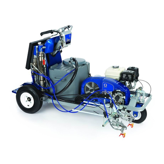
LineLazer IV 250
Self-Propelled Line Striper
For the application of line striping materials.
For professional use only.
For outdoor use only.
Not for use in hazardous locations or explosive atmospheres.
Maximum Operating Speed: 10 mph (16 kph)
Maximum Operating Pressure: 3300 psi (22.8 MPa, 228 bar)
IMPORTANT SAFETY INSTRUCTIONS
Read all warnings and instructions in this manual and the engine manual.
Be familiar with the controls and the proper usage of the equipment.
Save these instructions.
Related Manuals:
3A2090
Operation
3A2598
Parts
311254
Gun
309277
Pump
312307
Auto-Layout Applications Methods
332230
Pressurized Bead System (PBS)
332226
Bead Gun Kit (PBS)
SPS
3A2593C
EN
ti24910a
Advertisement
Table of Contents

Related Manuals for Graco LineLazer IV 250SPS


Summary of Contents for Graco LineLazer IV 250SPS
- Page 1 Repair LineLazer IV 250 3A2593C Self-Propelled Line Striper For the application of line striping materials. For professional use only. For outdoor use only. Not for use in hazardous locations or explosive atmospheres. Maximum Operating Speed: 10 mph (16 kph) Maximum Operating Pressure: 3300 psi (22.8 MPa, 228 bar) IMPORTANT SAFETY INSTRUCTIONS Read all warnings and instructions in this manual and the engine manual.
-
Page 2: Table Of Contents
Engine Replacement ..... . . 25 Graco Standard Warranty ....54 Removal . -
Page 3: Models
Models Models Model Series Guns Pressurized Bead System Description 24F307 A, B, C LLIV 250SPS (North America, Latin America, Asia Pacific) 24K960 A, B, C LLIV 250SPS (Latin America, Asia Pacific) 24K961 A, B, C LLIV 250SPS (Europe) 24K962 A, B, C LLIV 250SPS (Europe) 24M608 A, B, C... -
Page 4: Warnings
Warnings Warnings The following warnings are for the setup, use, grounding, maintenance, and repair of this equipment. The exclama- tion point symbol alerts you to a general warning and the hazard symbols refer to procedure-specific risks. When these symbols appear in the body of this manual or on warning labels, refer back to these Warnings. Product-specific hazard symbols and warnings not covered in this section may appear throughout the body of this manual where applicable. - Page 5 Warnings WARNING PRESSURIZED ALUMINUM PARTS HAZARD Use of fluids that are incompatible with aluminum in pressurized equipment can cause serious chemical reaction and equipment rupture. Failure to follow this warning can result in death, serious injury, or prop- erty damage. •...
- Page 6 Warnings WARNING BATTERY HAZARD Contents of an open The battery may leak, explode, cause burns, or cause an explosion if mishandled. battery can cause severe irritation and/or chemical burns. If on skin, wash with soap and water. If in eyes, flush with water for at least 15 minutes and get immediate medical attention. •...
-
Page 7: Component Identification (Striper)
Component Identification (Striper) Component Identification (Striper) ti24911b Hydraulic Fill Cap / Dipstick Operator Platform Hydraulic Oil Filter Paint Filter Paint Hopper (25 gallon / 95 liter) Prime / Drain Valve Handle Bar Height Adjustment Knob Displacement Pump Engine Recoil Handle (manual start engine only) Rear Gun Arm Mount, both sides Brake Serial Label, under operator platform... -
Page 8: Engine)
Component Identification (Controls, Manual Start Engine) Component Identification (Controls, Manual Start Engine) ti18719a Hydraulic Pump Valve Gun Trigger Control Forward / Reverse Lever Display Engine Throttle Engine Choke Gun 1 Selector Gun 2 Selector Engine Kill / Main Power Switch 10 12V Accessory Jack 11 Pressure Control 3A2593C Repair... -
Page 9: Engine)
Component Identification (Controls, Electric Start Engine) Component Identification (Controls, Electric Start Engine) ti25621a ti25621a Engine Key Switch, OFF - ON - START Display Forward / Reverse Lever Gun Trigger Control Engine Throttle Engine Choke Gun 1, 2 Selector Engine Clutch 12V Accessory Jack, both sides 10 Pressure Control 11 Hydraulic Pump Valve... -
Page 10: Grounding Procedure (For Flammable Materials Only)
Grounding Procedure (For Flammable Materials Only) Grounding Procedure Pressure Relief Procedure (For Flammable Materials Only) Follow the Pressure Relief Procedure whenever you see this symbol. This equipment must be grounded to reduce the risk of static sparking. Static sparking can cause fumes to This equipment stays pressurized until pressure is ignite or explode. -
Page 11: Ground Drive Belt Replacement
Ground Drive Belt Replacement Ground Drive Belt Installation Replacement 1. Install belt onto pulleys. Removal ti19134a 1. If equipped with a Pressurized Bead System, 2. Tighten tensioning bolt to move two pulleys apart remove pressurized bead tanks and compressor, and tighten belt to proper tension (see table). see Pressurized Bead System manual 332230. -
Page 12: Oil Reservoir Belt Replacement
Oil Reservoir Belt Replacement Oil Reservoir Belt Installation Replacement 1. Replace belt. Removal ti19149a 2. Tighten two adjustment bolts evenly and maintain NOTE: Ground drive belt must be removed before oil belt alignment. Tighten belt to proper tension (see reservoir belt can be replaced, see Ground Drive Belt table). -
Page 13: Hydraulic System Purging
Hydraulic System Purging Hydraulic System 5. Turn on the clutch. Purging This equipment stays pressurized until pressure is manually relieved. To help prevent serious injury ti18552a from pressurized fluid, such as skin injection, ti25622a Main Power Switch Clutch Switch splashing fluid and moving parts, follow the Pressure Relief Procedure when you stop spraying and before 6. -
Page 14: Ground Drive Pump Replacement
Ground Drive Pump Replacement Ground Drive Pump 5. Remove nut (3) and disconnect tie rod (40) under- neath pump (63). Replacement 6. Remove two mounting bolts (82) and washers (55) to remove pump (63) from bracket. Installation This equipment stays pressurized until pressure is 1. -
Page 15: Oil Reservoir Pump Replacement
Oil Reservoir Pump Replacement Oil Reservoir Pump 6. Remove pulley from pump. Remove four screws and pump from reservoir cover. Replacement This equipment stays pressurized until pressure is manually relieved. To help prevent serious injury from pressurized fluid, such as skin injection, ti19672a splashing fluid and moving parts, follow the Pressure Relief Procedure when you stop spraying and before... - Page 16 Oil Reservoir Pump Replacement 4. If cable has one set screw, install cable and tighten 6. Slide cable sleeve up and tighten screw. set screw on flat. ti19145a ti19143a 7. Connect three hydraulic hoses to fittings on oil reservoir. Replace oil filter. 5.
-
Page 17: Hydraulic Gun Manifold Replacement
Hydraulic Gun Manifold Replacement Hydraulic Gun Manifold 5. Label wire harnesses GUN 1 and GUN 2. Discon- nect two wire harnesses from solenoids. Replacement Gun 2 Gun 1 Removal ti19161a 1. Remove tank lid and siphon tube. 6. Label gun cables Gun 1 and Gun 2. Disconnect gun cables from actuators. -
Page 18: Installation
Hydraulic Gun Manifold Replacement 9. Disconnect manifold tubes at manifold. 4. Push Gun 1 and Gun 2 gun cables into bracket. NOTE: Be sure to connect Gun 1 cable to the hole 10. Remove two mounting bolts and slide hydraulic in the bracket closest to center of sprayer. -
Page 19: Paint Pump Replacement
Paint Pump Replacement Paint Pump Replacement 5. Use hammer to loosen pump jam nut (106). 6. Slide down retainer (104) and remove pin (105). 7. Unscrew and remove paint pump (107). This equipment stays pressurized until pressure is Installation manually relieved. To help prevent serious injury from pressurized fluid, such as skin injection, 1. -
Page 20: Hydraulic Motor Replacement
Hydraulic Motor Replacement Hydraulic Motor NOTICE Replacement Use a screwdriver to lift pump piston up to gain access to mounting bolts and avoid contact with pis- ton. Contact with pump mounting bolts can scratch and damage the pump piston. 6. Remove four mounting bolts (116) from hydraulic This equipment stays pressurized until pressure is motor and remove motor from sprayer. -
Page 21: Clutch Replacement
Clutch Replacement Clutch Replacement 7. Remove engine recoil starter and place a screw- driver through the recoil starter cup. Removal 1. Remove Ground Drive Belt, page 11. ti19696a 2. Remove Oil Reservoir Belt, page 12. 3. Remove two hold-down bolts for the ground drive pump bracket. -
Page 22: Installation
Clutch Replacement Installation 4. Install pulley (61) and torque three screws (81) to 10 ft-lb (13 N•m). 1. Install spacer (56) and key (60) onto crankshaft. Slide clutch (57) onto crankshaft. ti19216a 5. Install recoil starter onto engine. ti19214a 2. Align clutch and wire in bracket. ti19704a 6. -
Page 23: Engine Replacement
Engine Replacement Engine Replacement 5. Disconnect choke cable. NOTE: For Series A, B of 24F307, 24K960, 24K961, 24K962, 24M608 and Series A of 16V470, 16V471, 16V473, 16V474, 24U561 Removal ti19185a 6. Tie knot in rope by recoil starter to prevent rope from being pulled into recoil starter. -
Page 24: Installation
Engine Replacement Installation c. Insert cable sheathing under cable clamp and tighten screw. NOTE: For Series A, B of 24F307, 24K960, 24K961, d. Tighten screw on hex-shaped pivot. 24K962, 24M608 and Series A of 16V470, 16V471, 16V473, 16V474, 24U561 e. Verify proper operation of engine choke. 1. -
Page 25: Engine Replacement
Engine Replacement Engine Replacement 5. Disconnect throttle cable. NOTE: For Series C of 24F307, 24K960, 24K961, 24K962, 24M608 and Series B of 16V470, 16V471, 16V473, 16V474, 24U561 Removal ti19183a 6. Disconnect choke cable. 1. Remove clutch, see Clutch Replacement, page 21. NOTICE To reduce the risk of battery damage and shorts, always disconnect NEGATIVE (black wire) first. -
Page 26: Installation
Engine Replacement Installation b. Insert “Z” bend wire into hole furthest from pivot. c. Place cable sheathing under clamp and pull NOTE: For Series C of 24F307, 24K960, 24K961, cable against high speed stop screw. 24K962, 24M608 and Series B of 16V470, 16V471, 16V473, 16V474, 24U561 d. -
Page 27: Touch-Pad Replacement
Touch-Pad Replacement Touch-Pad Replacement Removal Installation 1. Remove six screws and control shroud. 1. Apply touch-pad to sheet metal. 2. Connect ribbon cable from touch-pad at display board. ti19098a 2. Disconnect ribbon cable from touch-pad at display board. ti19910a 3. Install control shroud with six screws. ti19910a 3. -
Page 28: Control Board, Toggle Switches And Display
Control Board, Toggle Switches and Display Replacement Control Board, Toggle 7. Remove six screws and control shroud. Switches and Display Replacement Removal 1. Remove Fuse to disconnect battery, page 33. 2. Remove tank lid and siphon tube. ti19098a 8. Remove two screws and splash shield. ti24916a ti24916a ti19701a... -
Page 29: Installation
Control Board, Toggle Switches and Display Replacement 11. If replacing the toggle switches loosen two screws 13. If replacing control board, disconnect all wires from holding the ferrite core. Disconnect cable and control board. Remove eight mounting screws and remove toggle switch board. remove control board. - Page 30 Control Board, Toggle Switches and Display Replacement 5. Feed toggle switches through control panel and 10. Install front shield and tighten six screws. install two toggle switch nuts. ti19691a ti19200a 6. Install Fuse, see page 33. Check control, switches and display. 11.
-
Page 31: Battery Replacement
Battery Replacement Battery Replacement 5. Lift battery and slide it back onto the platform. Dis- connect 1 or 2 red wires from battery. Removal 1. Battery may be removed from the back of the unit by sliding it out above the operator platform. 2. - Page 32 Battery Replacement 2. Pickup and slide battery into mounting position. 4. Place coiled paint hoses over bracket and secure Install battery hold down strap. with straps. 3. Connect 1 or 2 black wires to negative (-) post of the battery ti24104b 3A2593C Repair...
-
Page 33: Fuse Replacement
Fuse Replacement Fuse Replacement 3. If fuse is open, a wire has shorted to the frame or auxiliary lighting requires too much power. Check wiring or reduce auxiliary lighting before replacing 1. Remove fuse cover. fuse. 2. Use needle-nose pliers to remove old fuse and 4. -
Page 34: Forward/Reverse Cable Replacement
Forward/Reverse Cable Replacement Forward/Reverse Cable 7. At the handlebar, remove locknut (3) and ball joint Replacement (40) from handlebar forward/reverse lever. Remove ball joint (40) from cable (148) and save if not replacing. Loosen two nuts on cable (148) and remove from bracket. -
Page 35: Installation
Forward/Reverse Cable Replacement Installation 3. Install cable (148) into handlebar bracket and tighten two nuts. Install ball joint (40) onto cable. Install ball joint into handlebar forward/reverse lever 1. Install new cable (148) by following same route as and tighten locknut (3). old cable is being removed. -
Page 36: Steering Cable Replacement
Steering Cable Replacement Steering Cable 4. At the handlebar, remove locknut (3) and ball joint (40) from handlebar. Remove ball joint (40) from Replacement cable (48) and save if not replacing. Loosen two nuts on cable (48) and remove from bracket. Removal 1. -
Page 37: Installation
Steering Cable Replacement Installation 5. Install ball joint (40) onto cable (48) and match threads on other side of handlebar. Install ball joint (40) into handlebar and tighten locknut (3). 1. Install new cable (48) by following same route as old cable is being removed. -
Page 38: Front Wheel Replacement
Front Wheel Replacement Front Wheel Replacement 3. Remove two spacers (36) and wheel (35) from fork (34). Installation Removal 1. Insert two spacers (36) into wheel (35) and slide into 1. Apply parking brake. Raise front wheel off ground fork (34). and support frame on two jack stands. -
Page 39: Parking Brake Service
Parking Brake Service Parking Brake Service Installation 1. Install lever (14) with pin (B) and clip (13). Removal 2. Use screwdriver to install spring (15). 1. Remove tire, wheel hub, and fender. See Wheel Motor Removal, page 40. 2. Remove clips (13) from three pins (A). Remove pins and levers. -
Page 40: Rear Wheel And Wheel Motors
2. Remove four lug nuts (22) and wheel (16). 3. Remove pin (56), castle nut (21b) and wheel hub (22b). Wheel hub may require a wheel puller; not supplied by Graco. ti18589a Rear Wheel Installation 1. Replace wheel and install lug nuts. Alternately ti23945a tighten lug nuts opposite of each other. -
Page 41: Wheel Motor Installation
Rear Wheel and Wheel Motors Wheel Motor Installation 2. Remove tank from unit. 3. Use wrench to remove six screws from front shield 1. Connect two hydraulic hoses (112) to wheel motor and remove front shield from unit. (21a) and insert wheel motor (21a) into frame (1). 2. - Page 42 Rear Wheel and Wheel Motors Installation 5. Install wheel (16) and four lug nuts (22). 1. Install wheel sensor (4) and clamp (5) with screw (6). ti18589a 6. Lower jack. 7. Install front shield with six screws. ti23946a 2. Connect wheel sensor connector to wire harness. ti19200a 8.
-
Page 43: Troubleshooting
Troubleshooting Troubleshooting General ** For Series C of 24F307, 24K960, 24K961, 24K962, * For Series A, B of 24F307, 24K960, 24K961, 24K962, 24M608 and Series B of 16V470, 16V471, 16V473, 24M608 and Series A of 16V470, 16V471, 16V473, 16V474, 24U561 16V474, 24U561 Problem Cause... - Page 44 Change hydraulic filter and hydraulic oil. Intake line to pump inlet is not tight. Tighten intake line to pump inlet. Hydraulic motor is worn or damaged. Bring sprayer to Graco distributor for repair. Suction tube strainer is clogged. Clean strainer Suction tube air leak.
- Page 45 Troubleshooting Problem Cause Solution Turn pressure adjusting knob clockwise to increase Pressure setting too low. pressure. See operation manual. Low stall or run pressure shown on Pump break-in period takes up to 100 gallons display New pump or new packings. of material.
- Page 46 Gun does not apply dots Dot size setting is too small. Increase dot size. Pressure is too low. Increase pressure to 1000 psi. Use only Graco approved hydraulic fluid 169236 (5 gallons / 18.9 liter) or 207428 (1 gallon / 3.8 liter) 3A2593C Repair...
-
Page 47: Hydraulic Diagram
Hydraulic Diagram Hydraulic Diagram 3A2593C Repair... -
Page 48: Hydraulic Parts List
Hydraulic Diagram Hydraulic Parts List Ref. Part Description Ref. Part Description 126080 FITTING, tee, street 125929 MOTOR, wheel 126081 FITTING, nipple, 3/8-18 x #6 JIC 16M271 HOSE, coupled, assembly, LL250 16M160 COVER, reservoir, LL250, painted 247930 KIT, repair, hydraulic pump 16X083 KIT, repair, pump, 250 SPS 117328 FITTING, nipple, straight 122970 FITTING, hydraulic... -
Page 49: Wiring Diagram (Manual Start)
Wiring Diagram (Manual Start) Wiring Diagram (Manual Start) 3A2593C Repair... -
Page 50: Wiring Parts List (Manual Start)
Wiring Diagram (Manual Start) Wiring Parts List (Manual Start) NOTE: For Series A, B of 24F307, 24K960, 24K961, 24K962, 24M608 and Series A of 16V470, 16V471, Ref. Part Description 16V473, 16V474, 24U561 214c 24N564 KIT, repair, display board 214e 16N374 SWITCH, membrane 214f 24N566 KIT, repair, switch board Ref. -
Page 51: Wiring Diagram (Electric Start)
Wiring Diagram (Electric Start) Wiring Diagram (Electric Start) 3A2593C Repair... -
Page 52: Wiring Parts List (Electric Start)
Wiring Diagram (Electric Start) Wiring Parts List (Electric Start) NOTE: For Series C of 24F307, 24K960, 24K961, 24K962, 24M608 and Series B of 16V470, 16V471, Ref. Part Description 16V473, 16V474, 24U561 214e 16N374 SWITCH, membrane 214f 24N566 KIT, repair, switch board 214h 17C063 SWITCH, rocker, spst Ref. -
Page 53: Notes
Notes Notes 3A2593C Repair... -
Page 54: Graco Standard Warranty
With the exception of any special, extended, or limited warranty published by Graco, Graco will, for a period of twelve months from the date of sale, repair or replace any part of the equipment determined by Graco to be defective.