Table of Contents
Advertisement
Quick Links
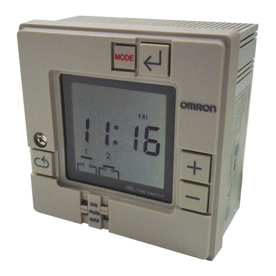
Weekly Timer
1/4 DIN Size Timer Features Prompted
Programming and Large LCD Display
24 hours x 7 days programming using
just 5 switches
16 program steps and cycle operation
Two independent 15 A control circuits
Manual override switch for each output
Easy-to-read, large, 0.5 inch high LCD
display
Wide operating voltage range
10-year battery backup for memory
protection
Hardware for panel and surface mounting
included; designed for track mounting
Protective cover and mounting track may
be ordered separately
Ordering Information
TIMERS
Part number
Supply voltage
Timing function
Contact type
Terminal form
TIME RANGES
Time setting range
Program capacity
Cycle length
Minimum cycle interval
ACCESSORIES
Description
Hard plastic cover
Mounting track
REPLACEMENT PARTS
Description
Surface mounting bracket; one supplied with each H5L timer
Flush mounting bracket; one supplied with each H5L timer
1
H5L-A
100 to 240 VAC, 50/60 Hz
Weekly timer, 24 hours x 7 days, ON and OFF programming
Two SPST time limit contacts with manual override switches
Screw terminals accessible from front and back
00:00 to 23:59 (hours:minutes)
16 steps: ON = 1 step, OFF = 1 step, CYCLE = 4 steps
1 minute to 23 hours 59 minutes
1 minute between OFF and ON periods
50 cm (1.64 ft) length
1 m (3.28 ft) length
End plate
H5L
Part number
Y92A-96A
PFP-50N
PFP-100N
PFP-M
Part number
H5L 2433983-6
H5L 2433982-8
Advertisement
Table of Contents

Related Manuals for Omron H5L Series


Summary of Contents for Omron H5L Series
- Page 1 Weekly Timer 1/4 DIN Size Timer Features Prompted Programming and Large LCD Display 24 hours x 7 days programming using just 5 switches 16 program steps and cycle operation Two independent 15 A control circuits Manual override switch for each output Easy-to-read, large, 0.5 inch high LCD display Wide operating voltage range...
-
Page 2: Specifications
Specifications Part number H5L-A Supply 100 to 240 V, 50/60 Hz voltage – Operating voltage 85 to 110% of rated voltage Power consumption 7 VA Timing functions 24 hours x 7 days, ON and OFF programming 16 steps; ON = 1 step, OFF = 1 step, CYCLE = 4 steps Control Type Time limit... -
Page 3: Engineering Data
Engineering Data AMBIENT OPERATING TEMPERATURE AND CARRY CURRENT The upper limit of the ambient operating temperature 60°C must be derated when a large carry current is being (140°F) applied. This case occurs when both circuits are 55°C energized simultaneously. (131°F) When both circuits are energized simultaneously 50°C... -
Page 4: Installation
Connections Power supply terminal numbers Output terminal numbers AC (common) AC (hot) Load 1 Load 2 7 and 8 5 and 6 If operating conditions exceed the noise Noise voltage: 2 KV values at right, connect a surge absorber to Pulse width: 100 ns prevent malfunction or damage to the... -
Page 5: Key Operations
Operation NOMENCLATURE Mode display Mode key Write key Day of week display Plus key Output status indication Minus key Output ON Output OFF Cycle key Manual override switch Invalid instruction written to a step KEY OPERATIONS Name Function Mode key Changes program mode MODE First circuit operation... -
Page 6: Programming Sequence
PROGRAMMING SEQUENCE Cycle program The cycle program in H5L can be used to repeat ON and OFF The H5L weekly timer has six program modes. Use the mode key output patterns for a length of time. A cycle program consists of to change the modes. -
Page 7: Programming Example
DELETING ON/OFF PROGRAM STEPS Use the MODE and WRITE keys to advance to the output status indicator of the steps to be deleted. Use the + and – keys to make the output status indicator invalid (no bar). Press the WRITE key and the step is deleted. DELETING CYCLE PROGRAM STEPS Use the MODE and WRITE keys to advance to the first step of the cycle program. - Page 8 Creating Timing Chart First circuit Second circuit Writing the Program Setting the current time To set the current time, "day of the week", "hour", and "minute" must be specified. First, turn on the power to the H5L. Press the Mode key for more than 1 sec. The TIM ADJ indicator is displayed.
- Page 9 First Circuit Operation Setting To program the operation of the first circuit, "hour", "minute", and "output" must be specified. Press the MODE key to set the H5L in PROG 1 mode. The display will be as shown on the left. Since the first circuit is turned ON at 7:40, set the "hour"...
- Page 10 Second Circuit Operation Setting Press the MODE key to set the H5L in PROG 2 mode. The display appears as shown on the left. In example 1, as the second circuit is to be cyclically operated, specify the cycle program by pressing the Cycle key. START Set the start time (6:50) first.
-
Page 11: Running The Program
Second Circuit Day-of-the-Week Setting Press the MODE key to set the H5L in the DAY SET mode of the PROG 2 mode. The display will be as shown on the left. As the initial condition, the second circuit is to be operated on all the days of the week, which means all the indications by the day indicators are reverse video except that of the SUN indicator which blinks. -
Page 12: Panel Mounting
Mounting The H5L timer comes with mounting brackets for panel and surface mounting. A slot on the back of the case allows H5L to be track mounted. PANEL MOUNTING Use the U-shaped mounting bracket supplied. Dimensions Panel cutout Flush mounting bracket (supplied) H5L 2433982-8 SURFACE MOUNTING... - Page 13 NOTE: ALL DIMENSIONS ARE IN MILLIMETERS. To convert millimeters into inches divide by 25.4. Omron Europe B.V. EMA-ISD, tel:+31 23 5681390, fax:+31 23 5681397, http://www.eu.omron.com/ema Cat . N o . GC TI8 11/97 Specifications subject to change without notice.