Zeiss OPMI LUMERA 700 User Manual
Hide thumbs
Also See for OPMI LUMERA 700:
- User manual (294 pages) ,
- Instructions for use manual (236 pages) ,
- Basic instructions (2 pages)
Table of Contents
Advertisement
Advertisement
Chapters
Table of Contents

Related Manuals for Zeiss OPMI LUMERA 700


Summary of Contents for Zeiss OPMI LUMERA 700
-
Page 1: User Manual
Carl Zeiss ® OPMI LUMERA User manual G-30-1673-en Version 7.3 2012-05-02... - Page 2 – A list of abbreviations, key words and technical terms in the annex facili- tates the search for specific terms. Scope of application The present operating manual applies to the OPMI LUMERA 700 with soft- ware release 2.0 and the following identification: – Reference number 6634 (floor stand) –...
- Page 3 OPMI LUMERA® 700 Chapter Overview Chapter: Safety Measures Chapter: System Overview Chapter: Preparations for use Chapter: Operation Chapter: What to do in the event of malfunctions Chapter: Care and Maintenance Chapter: System Data Chapter: Annex / Options Chapter: Indexes Version 7.3 G-30-1673-en Page 3...
- Page 4 OPMI LUMERA® 700 Version 7.3 Page 4 G-30-1673-en...
-
Page 5: Table Of Contents
OPMI LUMERA® 700 Safety Measures Safety Measures Key to symbols .................. 7 Hazard symbols ...................7 Information symbols..................7 Target group ..................8 Field of application ................8 Intended use ....................8 Normal use....................8 Notes for the operator..............10 Requirements for operation............. 13 Prior to the very first use................13 Before every use ..................13 During use....................15 After every use ..................16... - Page 6 Safety Measures OPMI LUMERA® 700 Labels on the suspension system............... 32 Labels on the lamp housing ..............42 Device connector signs ................44 Version 7.3 Page 6 G-30-1673-en...
-
Page 7: Key To Symbols
OPMI LUMERA® 700 Safety Measures Key to symbols We would like to inform you about safety aspects which must be observed when handling this device. This chapter contains a summary of the most im- portant information concerning matters relevant to instrument safety. Hazard symbols The following safety information has been incorporated into the instructions for use. -
Page 8: Target Group
Carl Zeiss. Field of application Intended use OPMI LUMERA 700 is a surgical microscope intended for the illumination and magnification of the surgical area and for the support of visualization in sur- gical procedures in the field of ophthalmology. - Page 9 OPMI LUMERA® 700 Safety Measures enables the surgeon to move the focus very easily over long distances (e.g. for folding lenses) and back to its initial position. Assistant functions such as the keratoscope, the data injection system or the integrated slit illuminator ex- pand the surgeon's scope of work.
-
Page 10: Notes For The Operator
• Modifications and repairs of this device or any equipment operated to- gether with this device may only be performed by Carl Zeiss service staff or other persons authorized by Carl Zeiss. • Connect the system to a special emergency backup power supply in ac- cordance with the regulations and directives applicable in the country of use. - Page 11 • Should the device be transported over longer distances (e.g., moving, re- turn for repairs etc.), only use the original packaging or special return packages. Please contact your dealer or the Carl Zeiss Service department. • In order to prevent a decrease in the device's safety due to age, wear and tear, etc., the user must have the device checked for its safe operation (re-...
- Page 12 Safety Measures OPMI LUMERA® 700 • Condensation of humid air may occur if you move the system from a cold place (<10°C) to a warm place. Before switching on the system, allow it to adapt to room temperature for at least 1 hour. •...
-
Page 13: Requirements For Operation
Safety Measures Requirements for operation Prior to the very first use Carl Zeiss Service or a person authorized by Carl Zeiss will install the device. Please make sure that the following requirements continue to be met for fur- ther operation: ... - Page 14 • Never attempt to forcefully connect any electrical connectors (plugs, sock- ets). If connection is not readily possible, check whether the plug fits the socket. If any of the connectors are damaged, have Carl Zeiss Service re- pair them. • Before using the wireless, foot control panel FCP WL ensure its batteries are fully charged.
-
Page 15: During Use
• In order to prevent phototoxic damages to the patient's eye, adjust the ir- radiation intensity and the associated irradiation time by selecting the ap- propriate illumination setting. The values recommended by Carl Zeiss can be found in table "Maximum radiation exposure times" on page 22. Any deviation from these values is only permissible when medically justified. -
Page 16: After Every Use
Safety Measures OPMI LUMERA® 700 • If you change the lamp shortly after it has failed, the lamp will still be very hot. Use heat-resistant protective gloves when replacing the lamp to pre- vent burns. • Malfunctions in the motor's electronic system may cause the main func- tions to fail (XY movement, focus, zoom, light control system) and affect other functions. -
Page 17: Liability And Warranty
OPMI LUMERA® 700 Safety Measures Liability and warranty Warranty and liability depend on the applicable contractual stipulations. NOTE Loss of warranty Modifications to this system are not permissible. The manufacturer is not li- able for damage caused by unauthorized persons tampering with the system. Furthermore, this will forfeit any rights to claim under warranty. -
Page 18: Measures To Prevent Phototoxic Injury
– Exposure time to light In the following, comments on these aspects are given and a description of how Carl Zeiss, as a manufacturer, makes allowance for them in its systems. Illumination characteristics (spectral composition) Studies on the exposure of the eye to light of varying spectral composition date back to the early 1950s. -
Page 19: Angle Of Illumination
Brightness control For this reason, the brightness of the light source in Carl Zeiss systems is con- tinuously variable. This permits the surgeon to optimally adapt the light inten- sity at the patient's eye to the conditions existing in each case. -
Page 20: Exposure Time To Light
This problem has been solved by Carl Zeiss by the use of a retina protection device that can be swung into the microscope's illumination beam path and a swing-in retina protection filter (blue barrier filter). - Page 21 OPMI LUMERA® 700 Safety Measures such as the phaco handpiece, and movement of the eye provide interruption of the exposure and would be expected to significantly lengthen the time be- fore photoretinitis might be expected to occur. A prospective study of the effects of microscope illumination during surgery Effects of microscope illumination...
- Page 22 Safety Measures OPMI LUMERA® 700 The following tables are intended to provide the surgeon with a guideline in Maximum radiation exposure times determining the potential hazard. The data has been calculated for the worst case: – direct radiation exposure, – uninterrupted radiation exposure, e.g., no surgical instruments in the eye, –...
- Page 23 OPMI LUMERA® 700 Safety Measures Maximum radiation exposure times with integrated slit illuminator in minutes Brightness level Halogen Xenon Xenon with LED with HaMode filter HaMode filter 18.4 11.5 31.0 15.5 10.3 100% H. Stiller, and B. Rassow, "Light hazards to the patient's retina from oph- Sources thalmic instruments,"...
-
Page 24: Safety Devices
Safety Measures OPMI LUMERA® 700 Safety devices 1 Release bar for magnetic brake Enables the person who is unsterile to activate the magnetic brake of the suspension system. 2 Adjustment screw for limiting downward movement Is used to set the minimum working distance of the surgical microscope to the operating area in the vertical direction. - Page 25 OPMI LUMERA® 700 Safety Measures Fig. 1: Safety Equipment Version 7.3 G-30-1673-en Page 25...
- Page 26 Safety Measures OPMI LUMERA® 700 9 Switch for manual operation In the event that one of the major functions fails (XY movement, focus, zoom, light control), leading to the impairment of further functions, you can press this switch to change to manual mode. The system reacts as follows: –...
- Page 27 OPMI LUMERA® 700 Safety Measures Fig. 2: Switch for Ceiling mount manual mode Floor stand Version 7.3 G-30-1673-en Page 27...
- Page 28 If the LED lights up amber, the LED light source is defective. In this case, the light intensity is reduced to 50% and an error message is displayed on the 5.7” control panel. • Please contact Carl Zeiss Service. 11 Flap indicating the operating status of the halogen lamps –...
- Page 29 OPMI LUMERA® 700 Safety Measures Fig. 3: Lamp housings Halogen Xenon Xenon + Halogen Version 7.3 G-30-1673-en Page 29...
-
Page 30: Symbols And Labels On The Device
Safety Measures OPMI LUMERA® 700 Symbols and labels on the device CAUTION Risk of injury! Observe all warnings and information labels! • When discovering that one of the following labels is missing on the equipment or a label has become illegible, please contact us or one of our authorized dealers. - Page 31 OPMI LUMERA® 700 Safety Measures Fig. 4: Labels on the microscope Version 7.3 G-30-1673-en Page 31...
- Page 32 Safety Measures OPMI LUMERA® 700 Labels on the suspension system 1 Friction information Explanation of brake effect, which can be achieved by actuating the fric- tion adjustment knob. 2 Warning label "Maximum load capacity" The maximum weight of the add-ons (accessory equipment) to the micro- scope must not exceed 9 kg! 3 "User manual"...
- Page 33 OPMI LUMERA® 700 Safety Measures Fig. 5: Labels on the suspen- sion system Version 7.3 G-30-1673-en Page 33...
- Page 34 Safety Measures OPMI LUMERA® 700 9 Rating label on ceiling mount The rating label contains the following information: – Manufacturer's mark – Manufacturer (company name) Carl Zeiss Meditec AG – Manufacturer's address Goeschwitzer Strasse 51-52 07745 Jena/Germany – Serial number –...
- Page 35 Safety Measures 10 Rating label on the floor stand The rating label contains the following information: – Manufacturing symbol – Manufacturer (company name) Carl Zeiss Meditec AG – Manufacturer's address Goeschwitzer Strasse 51-52 07745 Jena, Germany – Serial number – Device name OPMI Lumera 700 –...
- Page 36 – SIP number A unique identification number assigned to your system. A product file is maintained by Carl Zeiss for this SIP number. 12 Please follow disposal regulations Do not dispose of electrical and electronic waste with domestic waste. Ad- ditional information pertaining to the disposal of electrical and electronic waste can be found in Chapter "Maintenance and care"...
- Page 37 OPMI LUMERA® 700 Safety Measures Fig. 8: Labels on the suspen- sion system 14 15 16 Version 7.3 G-30-1673-en Page 37...
- Page 38 Safety Measures OPMI LUMERA® 700 18 "Maximum load on instrument tray" warning label Indicates that the maximum load capacity of the instrument tray for acces- sory equipment is 13 kg. 19 "Instructions for use" label Observe the instructions for use or accompanying documents. 20 USB port Identifies the connector e.g.
- Page 39 OPMI LUMERA® 700 Safety Measures Fig. 9: Labels on the suspen- sion system Version 7.3 G-30-1673-en Page 39...
- Page 40 Safety Measures OPMI LUMERA® 700 25 Lift switch label (optional) Indicates the lift switch on the ceiling mount. – Left position = lift arm moves up – Right position = lift arm moves down 26 "Work cycle for ceiling mount with lift arm" label (optional) This label represents the ratio (1:9) of the maximum allowed operating time to the idle phase of the lift arm that has to be maintained thereafter.
- Page 41 OPMI LUMERA® 700 Safety Measures Fig. 10: Special labels on the ceiling mount Version 7.3 G-30-1673-en Page 41...
- Page 42 Superlux Eye with lamp module and integrated filters 5 "CAUTION" label The Superlux Eye light source is a xenon light source that must only be op- erated with special xenon lamps approved by Carl Zeiss for ophthalmic surgery. 6 Changing the lamps The label shows the three steps for the replacement of a lamp.
- Page 43 OPMI LUMERA® 700 Safety Measures Fig. 12: Labels on halogen and Superlux Eye lamp housing Fig. 13: Labels on Superlux Eye lamp housing Version 7.3 G-30-1673-en Page 43...
- Page 44 Safety Measures OPMI LUMERA® 700 Device connector signs 1 Potential equalization For connection of the system to the potential equalization system. 2 "Connector for foot control panel" label 3 Remote connector This label identifies a connection on the device with max. 24V/0.5A 4 "CAUTION"...
- Page 45 OPMI LUMERA® 700 Safety Measures Fig. 14: Labels on the floor mount connectors Fig. 15: Connector signs on the standard wall mount Fig. 16: Labels for connectors on video wall mount SD video wall mount HD video wall mount Version 7.3 G-30-1673-en Page 45...
- Page 46 Safety Measures OPMI LUMERA® 700 Version 7.3 Page 46 G-30-1673-en...
-
Page 47: System Overview
System Overview System Overview System overview................48 OPMI LUMERA 700 (floor stand version)............48 OPMI LUMERA 700 (ceiling mount version) ..........50 Components of the surgical microscope ..........52 Controls of the main microscope and assistant's microscope .....66 Controls for the tubes................68 Controls for the widefield eyepieces ............69 Components of the XY coupling ............70... -
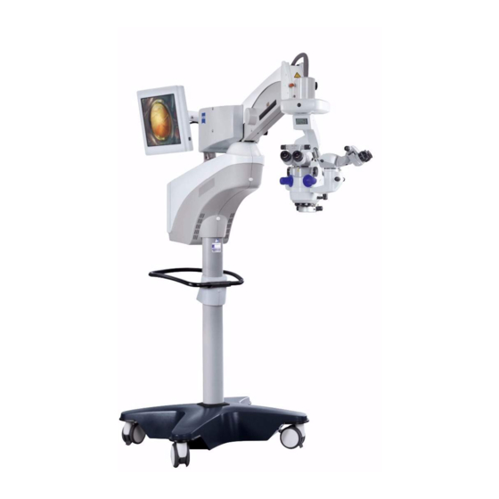
Page 48: Opmi Lumera 700 (Floor Stand Version)
– Integrated HD 3CCD camera (high definition) – Integrated 22" TFT with carrier arm – Integrated 22" TFT with carrier arm and device carrier for Zeiss devices such as, e.g., MEDIALINK 100, TRIO 610 or MediLive Trio Eye – CALLISTO eye –... - Page 49 OPMI LUMERA® 700 System Overview Fig. 17: System overview Version 7.3 G-30-1673-en Page 49...
-
Page 50: Opmi Lumera 700 (Ceiling Mount Version)
System Overview OPMI LUMERA® 700 OPMI LUMERA 700 (ceiling mount version) 1 Surgical microscope - page 52 2 XY coupling - 3 Suspension arm - page 72 4 Lamp housing with light sources - page 78 5 Lift arm or rigid arm - page 72... - Page 51 OPMI LUMERA® 700 System Overview Fig. 18: System overview (ceiling mount version) Version 7.3 G-30-1673-en Page 51...
-
Page 52: Components Of The Surgical Microscope
System Overview OPMI LUMERA® 700 Components of the surgical microscope 1 Tube for main and assistant's microscope The following tubes can be attached: – Invertertube - manually adjustable (optional) The tube can be tilted by 110°. It is particularly suitable for use in com- bination with a fundus viewing system, as it erects an inverted image. - Page 53 OPMI LUMERA® 700 System Overview Fig. 19: Components of the surgical microscope Version 7.3 G-30-1673-en Page 53...
- Page 54 System Overview OPMI LUMERA® 700 3 Slit illuminator (optional) The slit illuminator is an integratedadditional light source for OPMI LUMERA 700. It creates a bright, clearly delineated slit image for high-con- trast viewing of the front and back eye section. The slit position (right, left) and the size of the slit apertures (slit width 0.2 mm, 2 mm, 3 mm and 4 mm) are set using the 5.7”...
- Page 55 OPMI LUMERA® 700 System Overview Fig. 20: Components of the surgical microscope Version 7.3 G-30-1673-en Page 55...
- Page 56 System Overview OPMI LUMERA® 700 5 Keratoscope (optional) The keratoscope consists of a red LED illumination system that surrounds the objective lens as a ring. The feature is used to assess the shape of the cornea surface by observing and subjectively evaluating the pattern im- aged on the cornea.
- Page 57 OPMI LUMERA® 700 System Overview Fig. 21: Components of the surgical microscope Version 7.3 G-30-1673-en Page 57...
- Page 58 10 Connector for Invertertube E This connector permits you to control the motorized image inversion of In- vertertube E via OPMI LUMERA 700. If RESIGHT 700 is also connected, the two devices can be synchronized so that the field of view is always dis- played in the correct orientation.
- Page 59 OPMI LUMERA® 700 System Overview Fig. 22: Components of the surgical microscope Version 7.3 G-30-1673-en Page 59...
- Page 60 System Overview OPMI LUMERA® 700 11 Overhead display (optional) The following current information is displayed on the Data on the overhead display (see image on left) for the user and his/her user profile: overhead display – Light intensity in percent ( REC OFF If the light source is switched off, the bulb is shown unlit ( –...
- Page 61 OPMI LUMERA® 700 System Overview Fig. 23: Overhead display Version 7.3 G-30-1673-en Page 61...
- Page 62 12 IDIS – Integrated Data Injection System (optional) IDIS has been optimized for applications where CALLISTO eye and OPMI LUMERA 700 are used simultaneously. IDIS enables you to have the following information displayed in the right eyepiece and superimposed on the current microscope image.
- Page 63 To enable use of the K TRACK, Z ALIGN and RHEXIS assistance functions, OPMI LUMERA 700 must be connected to CALLISTO eye via a network (seepage 124). To enable use of the K TRACK assistance function, OPMI LUMERA 700 must feature an integrated keratoscope. NOTE...
- Page 64 13 Assistant's microscope The integrated assistant's microscope in its standard version comes as an integral part of OPMI LUMERA 700. The assistant sees the same image as the main surgeon in the same image quality and without any loss of light.
- Page 65 OPMI LUMERA® 700 System Overview Fig. 25: Components of the surgical microscope Version 7.3 G-30-1673-en Page 65...
-
Page 66: Controls Of The Main Microscope And Assistant's Microscope
System Overview OPMI LUMERA® 700 Controls of the main microscope and assistant's microscope 1 Clamping screw of the assistant's tube Locks the assistant's tube in place after it has been adjusted within its 12° rotational range 2 Rotary knob for zoom drive of assistant's microscope As an option, the assistant's microscope can also be fitted with a manually adjustable 5x magnification changer. - Page 67 OPMI LUMERA® 700 System Overview Fig. 26: Controls on the main assistant's microscope Version 7.3 G-30-1673-en Page 67...
-
Page 68: Controls For The Tubes
System Overview OPMI LUMERA® 700 Controls for the tubes 180° tiltable tube and inclined tube 1 Eyepiece mount 2 Pupillary distance (PD) adjustment knob The correct position has been reached when the two eyepiece images merge into one. You can read off the PD setting on the adjustment knob. Inverter tube and inverter tube E 3 Eyepiece mount 4 Knob for eye distance (interpupillary distance) -
Page 69: Controls For The Widefield Eyepieces
OPMI LUMERA® 700 System Overview Controls for the widefield eyepieces NOTE Widefield eyepieces with magnetic coupling Please note that the usual rules for the handling of magnets must be ob- served for eyepieces removed from the tube: • Do not place the eyepiece near instruments which may be magnetizable. •... -
Page 70: Components Of The Xy Coupling
System Overview OPMI LUMERA® 700 Components of the XY coupling Controls of the XY coupling CAUTION Risk of injury! When pressing the XY reset button, the device may be put in focus and can be lowered. • Ensure the working distance between microscope and the patient is al- ways larger than the moving range of the microscope. - Page 71 OPMI LUMERA® 700 System Overview Fig. 29: Controls of XY coupling Version 7.3 G-30-1673-en Page 71...
-
Page 72: Floor Stand And Ceiling Mount Components
System Overview OPMI LUMERA® 700 Floor stand and ceiling mount components CAUTION Risk of injury caused by collisions! The ceiling mount may collide with other moving parts of the ceiling mount system (e.g., carrier arm with 22" video monitor). • Always ensure that you position moving parts slowly to avoid potential collisions. - Page 73 OPMI LUMERA® 700 System Overview Fig. 30: Components of ceiling mount and floor stand Version 7.3 G-30-1673-en Page 73...
- Page 74 System Overview OPMI LUMERA® 700 3 Carrier arm system for video monitors on the ceiling mount (optional) The height-adjustable carrier arm system consists of a suspension arm (3a), height-adjustable 3-joint carrier arm (3b), and monitor holder (3c) with VESA-100 interface. The VESA-100 interface serves for at- tachment and alignment of the following accessories: CAUTION Incorrect diagnosis from video images!
- Page 75 OPMI LUMERA® 700 System Overview Fig. 31: Components of ceiling mount and floor stand Version 7.3 G-30-1673-en Page 75...
- Page 76 Use the straps included in the delivery package to secure further ac- cessories. 5 Instrument tray (optional) The instrument tray is designed for holding the Zeiss units, MEDIALINK 100, VISULAS 532s or MediLive Trio. 6 Carrier arm for monitors on the floor stand (optional) The carrier arm serves for attachment and alignment of the integrated 22"...
- Page 77 OPMI LUMERA® 700 System Overview Fig. 32: Components of ceiling mount and floor stand Version 7.3 G-30-1673-en Page 77...
- Page 78 System Overview OPMI LUMERA® 700 7 Lamp housing The light source(s) in the lamp housing supplies/supply light to the SCI il- lumination system and the additional illuminator (e.g. VISULUX fiber slit il- luminator). The device can be equipped with one of the following light source combinations: Main light source Additional light...
- Page 79 OPMI LUMERA® 700 System Overview Fig. 33: Components of ceiling mount and floor stand Version 7.3 G-30-1673-en Page 79...
- Page 80 System Overview OPMI LUMERA® 700 The lamp housing (7) with the halogen light source features a fiber optic Halogen (optional) illuminator and a motor-driven filter wheel. The integrated automatic lamp changer ensures that a backup lamp is automatically swung into the illumination beam path if the first lamp fails.
- Page 81 OPMI LUMERA® 700 System Overview Fig. 34: Components of ceiling mount and floor stand Version 7.3 G-30-1673-en Page 81...
- Page 82 • Adjust the intensity of the irradiation and the resulting irradiation time by selecting the appropriate illumination setting. The values recommended by Carl Zeiss can be found in table "Maximum radiation exposure times" in Chapter "Safety measures". 9 Stand column A handle mounted on the stand column facilitates moving the system.
- Page 83 OPMI LUMERA® 700 System Overview Fig. 35: Components of the floor stand 13 12 11 Version 7.3 G-30-1673-en Page 83...
-
Page 84: Controls Of The Lamp Housing
If the LED is shining amber, the LED light source is defective. In this case, the light intensity reduces to 50% and an error message is displayed on the 5.7" control panel. • Please contact Carl Zeiss Service. 2 Flap indicating the operating status of the halogen lamps Halogen light source –... - Page 85 OPMI LUMERA® 700 System Overview Fig. 36: Lamp housings Halogen Xenon Xenon + Halogen Version 7.3 G-30-1673-en Page 85...
-
Page 86: Controls On The Suspension Arm
System Overview OPMI LUMERA® 700 Controls on the suspension arm 1 Rotary knob for limiting downward movement Serves to set the minimum working distance from the surgical field in ver- tical direction. See page 150. 2 Locating device of suspension arm Serves to prevent the suspension arm from shooting up or falling down when accessories are attached to or removed from the microscope. - Page 87 OPMI LUMERA® 700 System Overview Fig. 38: Controls on the suspension arm of the ceiling mount Version 7.3 G-30-1673-en Page 87...
-
Page 88: Controls On The Standard Wall Panel Of The Ceiling Mounts And On The Control And Display Panel Of The Floor Stand
System Overview OPMI LUMERA® 700 Controls on the standard wall panel of the ceiling mounts and on the control and display panel of the floor stand 1 5.7" control panel with touchscreen functionality The 5.7" control panel is the central communication interface of the system. - Page 89 OPMI LUMERA® 700 System Overview Fig. 39: Display and control panel Version 7.3 G-30-1673-en Page 89...
-
Page 90: Connector Panel On The Floor Stand
500 VA With the direct network connection between OPMI LUMERA 700 and CALLISTO eye (optional, the two devices must first be interconnected using a LAN cable. Afterwards, OPMI LUMERA 700 must be switched on and then CALLISTO eye. Version 7.3... - Page 91 CAUTION Hazard caused by electrical voltage! Only connect accessories and medical devices intended by Carl Zeiss for use with this system to the power outlet socket (see page 292). When con- necting other devices, make sure that safety is guaranteed regarding admis- sible touch currents and ground leakage currents as per IEC 60601-1:2006.
- Page 92 (e.g. BNC lines already installed on site). 13 Video output "Y/C" or S-Video (green) Analog port for video components, such as recorder, beamer and Zeiss ac- cessories. Here, the video signal is transmitted according to the S-Video or Y/C standard (separate lines for brightness and color signals).
- Page 93 OPMI LUMERA® 700 System Overview Fig. 41: Video ports with integrated SD 3CCD camera Version 7.3 G-30-1673-en Page 93...
- Page 94 (e.g. for BNC lines already laid on site). 16 Video output "Y/C" or S-Video (green) Analog port for video components, such as recorder, beamer and Zeiss ac- cessories. Here, the video signal is transmitted according to the S-Video or Y/C standard (separate lines for brightness and color signals).
- Page 95 OPMI LUMERA® 700 System Overview Fig. 42: Video ports with integrated HD 3CCD camera 16 17 18 19 Version 7.3 G-30-1673-en Page 95...
-
Page 96: Ceiling Mount Terminal Panels
Ports on the standard wall panel 2 Connector for wired foot control panel 3 Service interface for exporting error messages for Carl Zeiss Service. 4 Remote connector for controlling external devices with a maximum breaking capacity of 24V/ 0.5A. - Page 97 OPMI LUMERA® 700 System Overview Fig. 43: Connectors on the ceiling mount on the standard wall mount Version 7.3 G-30-1673-en Page 97...
- Page 98 • Do not connect any defective or unapproved accessories to the plug con- nector contacts. 6 Video output "Y/C" or S-Video (green) Analog port for video components, such as recorder, beamer and Zeiss ac- cessories. Here, the video signal is transmitted according to the S-Video or Y/C standard (separate lines for brightness and color signals).
- Page 99 OPMI LUMERA® 700 System Overview Fig. 44: Ports for the integrated SD 3CCD camera Version 7.3 G-30-1673-en Page 99...
- Page 100 • Do not connect any defective or unapproved accessories to the plug con- nector contacts. 9 Video output "Y/C" or S-Video (green) Analog port for video components, such as recorder, beamer and Zeiss ac- cessories. Here, the video signal is transmitted according to the S-Video or Y/C standard (separate lines for brightness and color signals).
- Page 101 OPMI LUMERA® 700 System Overview 13 Video output "Composite" (CVBS) Analog port for video components, e.g., recorder, projector or Zeiss accesso- ries such as MediLive Mindstream. The video signal is output in accordance with the CVBS standard (shared line for brightness/ color signals). This kind of transmission is suitable when the video signal is to be sent over large distances (e.g., if BNC lines are already laid...
-
Page 102: Connector Panel On The 22" Tft
System Overview OPMI LUMERA® 700 Connector panel on the 22" TFT 1 DC voltage connection is used to supply the device with electrical energy 12 V DC +/-10% < 5 A DC 2 RS232 port Serial interface 3 Video port "Composite" (CVBS) Analog port. - Page 103 OPMI LUMERA® 700 System Overview Fig. 46: Ports on the 22“ TFT Version 7.3 G-30-1673-en Page 103...
-
Page 104: Components Of The Foot Control Panel
System Overview OPMI LUMERA® 700 Components of the foot control panel The foot control panel permits you to control various functions of OPMI LUMERA 700. The assignment of the functions to the buttons on the foot control panel is shown on the following page. You can only activate functions that are implemented in the respective system configuration (suspension system, surgical microscope). - Page 105 Rocker switches The default settings (focus/zoom) of the rocker switches are preconfigured horizontally or vertically for each country. However, a Carl Zeiss service tech- nician can change the settings at any time. You can, however, customize the settings yourself at any time (see page 199).
- Page 106 System Overview OPMI LUMERA® 700 Version 7.3 Page 106 G-30-1673-en...
-
Page 107: Preparations For Use
(optional)..............120 Connecting external video equipment on integrated HD 3CCD camera to the floor stand (optional)..............122 OPMI LUMERA 700 with integrated data injection system IDIS (optional) 124 Network connection OPMI LUMERA 700 (floor mount) with CALLISTO eye ..................126 Positioning and connecting the floor mount .........128... -
Page 108: Operation
Preparations for use OPMI LUMERA® 700 Adjusting the surgical microscope ..........150 Adjusting the downward travel limit ............150 Positioning the assistant's microscope ............ 151 Adjusting the surgical microscope............152 Setting the tilt position ................154 Aligning the video monitor on the floor stand (optional) ......155 Aligning the carrier arm system on the ceiling mount (optional).... - Page 109 OPMI LUMERA® 700 Preparations for use Version 7.3 G-30-1673-en Page 109...
-
Page 110: Positioning And Connecting The Floor Mount
Preparations for use OPMI LUMERA® 700 Positioning and connecting the floor mount Relocating the system CAUTION Risk of tipping! Be careful when moving the device across sills; it may easily tip and/or injure a person next to it. • When lifting or pulling the system across a doorsill request the help of a second person. - Page 111 OPMI LUMERA® 700 Preparations for use Fig. 47: Transport position of the 22“ TFT Version 7.3 G-30-1673-en Page 111...
-
Page 112: Positioning The Device In The Or
Preparations for use OPMI LUMERA® 700 Positioning the device in the OR Position the device as follows: • Unlock all locking tabs. • Hold the device by the transport handle (1) and move it carefully into a po- sition convenient for you (such as that shown below). –... - Page 113 OPMI LUMERA® 700 Preparations for use Fig. 48: OR scene Version 7.3 G-30-1673-en Page 113...
-
Page 114: Connecting The System To The Power Supply
Preparations for use OPMI LUMERA® 700 Connecting the system to the power supply NOTE Tripping hazard! Cables inappropriately routed on the floor may constitute a tripping hazard. • Always route cables in a manner that will not obstruct the workflow. NOTE Risk of damaging the device! Prior to leaving the factory, the device is adjusted to the rated voltage of the... - Page 115 OPMI LUMERA® 700 Preparations for use Fig. 49: Connecting the system Version 7.3 G-30-1673-en Page 115...
-
Page 116: Pairing With The Wireless Foot Control Panel (Fcp-Wl)
Preparations for use OPMI LUMERA® 700 Pairing with the wireless foot control panel (FCP-WL) Pairing means the fixed relative assignment of the suspension system and foot control panel. It is required for wireless operation. On first-time pairing, it may take up to 20 s until the radio link between the suspension system and the foot control panel has been established. - Page 117 OPMI LUMERA® 700 Preparations for use Fig. 50: Connecting the wired foot control panel Version 7.3 G-30-1673-en Page 117...
-
Page 118: Connecting The Strain Relief Device
Preparations for use OPMI LUMERA® 700 Connecting the strain relief device Use the strain relief device (1) to prevent that the connected cables are inad- vertently pulled out. Make sure that the remaining cable length between the strain relief device (7) and the connector (8) is approx. 320 mm. Secure the cable in the strain relief device as follows: •... - Page 119 OPMI LUMERA® 700 Preparations for use Fig. 51: Connecting the strain relief device 320 mm Version 7.3 G-30-1673-en Page 119...
-
Page 120: Connecting External Video Equipment To Integrated Sd 3Ccd Camera To The Floor Stand (Optional)
10 m video in/out connecting cable Connecting the SD video monitor • Connect the analog Y/C video output port of the OPMI LUMERA 700 to the Y/C video input port of your SD video monitor, using the following vid- eo cable: –... - Page 121 OPMI LUMERA® 700 Preparations for use Fig. 52: External video equipment on integrated SD 3CCD camera Video in/out SD signal MEDIALINK 100 SD signal SD signal Endoscope SD video monitor camera SD video monitor SD video monitor Version 7.3 G-30-1673-en Page 121...
-
Page 122: Connecting External Video Equipment On Integrated Hd 3Ccd Camera To The Floor Stand (Optional)
EMC interference. • Connect the digital DVD D video output port of the OPMI LUMERA 700 to the DVI-D or BNC video input port of your HD video monitor, using one of the following video cables (depending on the connector type): –... - Page 123 OPMI LUMERA® 700 Preparations for use Fig. 53: External video equipment on integrated HD 3CCD camera DVI-D MEDIALINK 100 HD signal SD signal SD signal SD video monitor SD video monitor HD video monitor Version 7.3 G-30-1673-en Page 123...
-
Page 124: Opmi Lumera 700 With Integrated Data Injection System Idis (Optional)
To use IDIS, you must connect OPMI LUMERA 700 to the operation terminal of CALLISTO eye as follows: A video signal of the integrated OPMI LUMERA 700 HD 3CCD or SD 3CCD camera must be available on the CALLISTO eye for the injection system of the assistance functions. - Page 125 OPMI LUMERA® 700 Preparations for use Fig. 54: OPMI LUMERA 700 Underside with IDIS OPMI LUMERA 700 Underside of CALLISTO eye Version 7.3 G-30-1673-en Page 125...
-
Page 126: Network Connection Opmi Lumera 700 (Floor Mount) With Callisto Eye
• Switch off OPMI LUMERA 700 and CALLISTO eye. • Disconnect CALLISTO eye from the power supply. • Connect the network connection of OPMI LUMERA 700 (1) to the net- work connection (2) of CALLISTO eye. • Reconnect CALLISTO eye to the power cable. - Page 127 OPMI LUMERA® 700 Preparations for use Fig. 55: Direct OPMI LUMERA 700 network connection CALLISTO eye Fig. 56: Indirect OPMI LUMERA 700 network connection using a network distributor (switch) Network distributor CALLISTO eye Version 7.3 G-30-1673-en Page 127...
-
Page 128: Positioning And Connecting The Floor Mount
Preparations for use OPMI LUMERA® 700 Positioning and connecting the floor mount Positioning the device in the OR Positioning the ceiling mount with lift arm 1 Standby position 2 Working position CAUTION Risk of injury to the patient! Making a motor-driven lift arm readjustment during the operation might in- jure the patient. - Page 129 OPMI LUMERA® 700 Preparations for use • To raise the lift arm, turn the lift switch (4) to the left and hold it in that position until the lift arm has reached the topmost position. • After releasing the lift switch (4), the lift arm is locked in standby position (1).
- Page 130 Preparations for use OPMI LUMERA® 700 Ceiling mount with rigid arm 1 Standby position 2 Working position Proceed as follows to position the ceiling mount with rigid arm: Setting the working position • While pressing and holding the brake release button (4), use the handgrips (3) to move the surgical microscope to the desired working po- sition (2).
- Page 131 OPMI LUMERA® 700 Preparations for use Fig. 58: Positioning the ceiling mount with rigid arm Version 7.3 G-30-1673-en Page 131...
- Page 132 Preparations for use OPMI LUMERA® 700 Standby position of ceiling mount 1 Swivel axis of ceiling mount 2 Swivel axis of carrier arm system for video monitors CAUTION Risk of injury caused by collisions! The ceiling mount may collide with other moving parts of the ceiling mount system (e.g., carrier arm with 22"...
- Page 133 OPMI LUMERA® 700 Preparations for use Fig. 60: Examples of incorrect standby positions Version 7.3 G-30-1673-en Page 133...
-
Page 134: Example Or Situations
Preparations for use OPMI LUMERA® 700 Example OR situations 1 Surgeon 2 Assistant 3 Sterile nurse 4 OPMI LUMERA 700 Example OR situation 1 for ophthalmic surgery with an assistant on the right side. Fig. 61: Example OR situation 1 Version 7.3... - Page 135 OPMI LUMERA® 700 Preparations for use Example OR situation 2 for ophthalmic surgery with an assistant on the right side. Fig. 62: Example OR situation 2 Example OR situation 3 for ophthalmic surgery with an assistant on the left side. Fig.
-
Page 136: Pairing With Wireless Foot Control Panel (Fcp-Wl)
Preparations for use OPMI LUMERA® 700 Pairing with wireless foot control panel (FCP-WL) Pairing means the fixed relative assignment of the suspension system and foot control panel. It is required for wireless operation. On first-time pairing, it may take up to 20 s until the radio link between the suspension system and the foot control panel has been established. - Page 137 OPMI LUMERA® 700 Preparations for use Fig. 64: Connecting the foot control panel Version 7.3 G-30-1673-en Page 137...
-
Page 138: Connecting External Video Equipment On Integrated Sd 3Ccd Camera To The Floor Stand (Optional)
10 m video in/out connecting cable Connecting the SD video monitor • Connect the analog Y/C video output port of the video wall mount on OPMI LUMERA 700 to the Y/C video input port of your SD video monitor, using the following video cable: –... - Page 139 OPMI LUMERA® 700 Preparations for use Fig. 65: External video devices on integrated SD 3CCD camera Video in/out SD signal MEDIALINK 100 SD signal SD signal Endoscope SD video monitor camera SD video monitor SD video monitor Version 7.3 G-30-1673-en Page 139...
-
Page 140: Connecting External Video Equipment On Integrated Hd 3Ccd Camera To The Floor Stand (Optional)
(302681-8767-000), make sure to plug the connector with the ferrite core into the suspension system in order to avoid EMC interference. • Connect the digital DVI-D video output port on the OPMI LUMERA 700 to the video input port (e.g., DVI-D or BNC) of your HD video monitor, using one of the following video cables (depending on the connector type): –... - Page 141 OPMI LUMERA® 700 Preparations for use Fig. 66: External video equipment on integrated HD 3CCD camera HD-SDI DVI-D MEDIALINK 100 HD signal SD signal SD signal SD video monitor SD video monitor HD video monitor Version 7.3 G-30-1673-en Page 141...
-
Page 142: Mounting Accessories On The Surgical Microscope
Preparations for use OPMI LUMERA® 700 Mounting accessories on the surgical microscope Replacing components and accessories CAUTION Risk of injury! The swivel arm may move downward when accessories are changed. • Never exceed the maximum permissible weight capacity of the suspen- sion arm (see page 272). - Page 143 OPMI LUMERA® 700 Preparations for use Fig. 67: Components change Version 7.3 G-30-1673-en Page 143...
- Page 144 Preparations for use OPMI LUMERA® 700 • Attach one of the tubes (3) described on page 52 to the microscope body and firmly tighten the securing screws (6). • Attach one of the tubes (14) described onpage 52 to the integrated assist- ant's microscope and firmly tighten the securing screw (10).
- Page 145 OPMI LUMERA® 700 Preparations for use Fig. 68: Components change Version 7.3 G-30-1673-en Page 145...
-
Page 146: Connecting Invertertube E And Resight 700 (Optional) To The Surgical Microscope
Preparations for use OPMI LUMERA® 700 Connecting Invertertube E and RESIGHT 700 (optional) to the surgical microscope The two Invertertube E units are mounted (see page 142). • Plug the connecting cable on Invertertube E into the Invertertube connec- tion (2) on the surgical microscope. - Page 147 OPMI LUMERA® 700 Preparations for use Fig. 69: Fixing the connecting cable with a cable clip Version 7.3 G-30-1673-en Page 147...
-
Page 148: Connecting The Second Light Guide To The Accessories
Preparations for use OPMI LUMERA® 700 Connecting the second light guide to the accessories CAUTION Risk of injury! A second light guide, which freely hangs from the surgical microscope, may cause retinal damage or slight burns to the patient. • Always turn off the light source for the light guide that is not in use. •... -
Page 149: Balancing The System
OPMI LUMERA® 700 Preparations for use Balancing the system Rebalance the system after every change of accessories. Do not perform the balancing procedure until all accessories have been mounted and there is no patient under the surgical microscope! CAUTION Risk of crushing! Risk of crushing hands or fingers between suspension arm and XY coupling. -
Page 150: Adjusting The Surgical Microscope
Preparations for use OPMI LUMERA® 700 Adjusting the surgical microscope Adjusting the downward travel limit CAUTION Risk of injury! An improperly balanced systems will move upward or downward. • Limit the stroke of the suspension arm to prevent any contact with the patient if the surgical microscope is lowered accidentally.