Zeiss OPMI LUMERA 700 Instructions For Use Manual
Surgical microscope, software release 3.1
Hide thumbs
Also See for OPMI LUMERA 700:
- User manual (294 pages) ,
- User manual (150 pages) ,
- Basic instructions (2 pages)
Table of Contents
Advertisement
Quick Links
Advertisement
Table of Contents
Troubleshooting

Related Manuals for Zeiss OPMI LUMERA 700


Summary of Contents for Zeiss OPMI LUMERA 700
- Page 1 OPMI LUMERA 700 Software Release 3.1 Instructions for Use...
- Page 2 OPMI LUMERA, RESIGHT, SCI, Superlux, VISULUX, Visionguard and Z ALIGN are either trademarks or registered trademarks of Carl Zeiss Meditec AG or other companies of the ZEISS Group in Germany and/or other countries. All other trademarks mentioned in this document are the property...
-
Page 3: Table Of Contents
Instructions for Use Table of contents OPMI LUMERA 700 Table of contents Notes on Instructions for Use.............. 11 Device name ........................ 11 Area of application ...................... 11 Purpose and storage of the documentation ............... 11 Questions and comments .................... 11 Conventions in this document .................... 11 1.5.1... - Page 4 Table of contents Instructions for Use OPMI LUMERA 700 3.2.4 Suspension arm .......................... 39 3.2.5 XY coupling............................. 39 3.2.6 Overhead display.......................... 40 3.2.7 Surgical microscope......................... 40 3.2.8 Assistant's microscope ........................ 42 3.2.9 14-function foot control panel ...................... 43 3.2.10 Stand base ............................ 43 3.2.11 Stand column .......................... 44 3.2.12...
- Page 5 Instructions for Use Table of contents OPMI LUMERA 700 3.5.3 Main and auxiliary light source ...................... 81 3.5.4 Total magnification ......................... 82 3.5.5 Fast focus............................ 82 3.5.6 RESIGHT functions........................... 83 3.5.7 DeepView ............................ 83 3.5.8 Reset options .......................... 83 3.5.9 Links.............................. 84 3.5.10 Manual mode.......................... 84 3.5.11 Assistant's microscope ........................ 85 3.5.12...
- Page 6 Table of contents Instructions for Use OPMI LUMERA 700 Safety during preparation.................... 123 Switching the device on .................... 124 Function test ........................ 125 6.3.1 Device function tests ........................ 125 6.3.2 Function tests for device with fundus viewing system.............. 126 Preparing the system for sterile use ................. 127 6.4.1...
- Page 7 Instructions for Use Table of contents OPMI LUMERA 700 7.5.11 Ending control via CALLISTO eye .................... 173 Typical operating sequence .................... 174 7.6.1 Starting work .......................... 174 7.6.2 Carrying out the working steps...................... 175 7.6.3 Stopping work .......................... 175 Switching the device off .................... 176 Cleaning and disinfection ................. 177 Safety during cleaning and disinfection................ 177...
- Page 8 Table of contents Instructions for Use OPMI LUMERA 700 10.4.9 Increasing mobility of the monitor mount on the integrated CALLISTO eye Panel PC support arm . 197 10.4.10 Establishing cable connections for the 14-function foot control panel ........... 198 10.4.11 Displaying the firmware versions .................... 198 10.4.12 Opening the service menu ...................... 198...
- Page 9 Instructions for Use Table of contents OPMI LUMERA 700 12.3 Components ........................ 217 12.3.1 Tubes for surgical and assistant's microscopes................ 217 12.3.2 Eyepieces for surgical and assistant's microscopes ................. 217 12.3.3 Intermediate pieces for surgical microscope .................. 217 12.3.4 Objective lenses.......................... 218 12.3.5 Coobservation .......................... 218 12.3.6...
- Page 10 Empty page, for your notes...
-
Page 11: Notes On Instructions For Use
If you have any questions or comments concerning these Instructions for Use or the device itself, please contact ZEISS Service. You can find the ZEISS contact partner for your country on the following website: www.zeiss.com/med 1.5 Conventions in this document Certain types of information are specially marked in this document for better recognition. -
Page 12: Conventions In A Course Of Action
1 Notes on Instructions for Use Instructions for Use 1.5 Conventions in this document OPMI LUMERA 700 Names of software dialogs, fields or menus, and software messages are marked by quotation marks: • "View" menu. • "Do you want to save the settings?"... -
Page 13: Other Applicable Documents
Instructions for Use 1 Notes on Instructions for Use OPMI LUMERA 700 1.6 Other applicable documents 1.6 Other applicable documents Document type Document title Optional Product overview ZEISS Video Accessories Instructions for Use Preparation of Resteril- izable Products Instructions for Use... - Page 14 Empty page, for your notes...
-
Page 15: Safety Notes
2.2 Area of use 2.2.1 Intended use The OPMI LUMERA 700 is a surgical microscope designed for the illumination and magnification of the surgical area and for the support of visualization in surgical procedures in the field of ophthalmology. -
Page 16: Responsibilities And Duties Of The Operator
2 Safety notes Instructions for Use 2.3 Responsibilities and duties of the operator OPMI LUMERA 700 When finished, the surgeon swivels the microscope out of the surgical field and into the park position. Pressing the reset button on the XY coupling, or positioning the device in the park position, resets the device to its initial values and makes it ready for the next operation. -
Page 17: Messages To Manufacturer And Authorities
Accessories and additional equipment If you want to connect accessories or additional equipment to the device: Contact your ZEISS contact partner [} 11]. Any additional equipment connected to medical electrical devices must demonstrably comply with the applicable IEC or ISO standards (e.g. -
Page 18: Measures And Duties Of The Operator
2 Safety notes Instructions for Use 2.4 Measures and duties of the operator OPMI LUMERA 700 2.4 Measures and duties of the operator Electrical safety Always switch off the device before connecting it to or discon- necting it from the power supply, for cleaning its surface, or if it will not be used for a prolonged period of time. -
Page 19: Electromagnetic Compatibility
• Other devices set up in the vicinity or stacked together with the device. • Accessories, cables and spare parts not specified in the Instruc- tions for Use and not sold by ZEISS as spare parts. You can prevent EMC disturbances by using the following precau- tionary measures: Please comply with the Instructions for Use. -
Page 20: Before Every Use
Never attempt to forcefully connect any electrical connectors. If a connection cannot be made, check to make sure the plug fits the socket. If any of the connectors are damaged, have the ZEISS Service team or an authorized service representative repair them. 20 / 236... - Page 21 Instructions for Use 2 Safety notes OPMI LUMERA 700 2.6 Requirements for operation Hazards arising from moving components The following safety measures should be observed in order to prevent injuries or damage: Make certain to compensate for any added weight to the device;...
-
Page 22: During Operation
To prevent phototoxic damage to the patient's eye: Use the lowest brightness setting possible. Select an appropriate brightness setting according to the recommended values provided by ZEISS (see "Maximum radiation exposure times" [} 27]). Doing this limits the exposure intensity and the exposure time. -
Page 23: After Every Use
If an error occurs which cannot be fixed by using the "Troubleshooting" section: Mark the device as non-functional. Notify ZEISS Service or an authorized service representative. 2.6.4 After every use Hazards arising from a lack of supervision If the device is switched on, but not supervised, it may cause injuries or damage. -
Page 24: Measures To Prevent Phototoxic Injury
• Focus of the light source • Exposure time to light In the following, comments on these aspects are given and a description of how ZEISS, as a manufacturer, makes allowance for them in its systems. 2.7.1 Illumination characteristics (spectral composition) Studies on exposing the eye to light with varying spectral composi- tions have been conducted since as early as the 1950s. -
Page 25: Angle Of Illumination
This problem has been solved by ZEISS through the use of a swing- in retina protection filter (blue barrier filter) that can be swung into the microscope's illumination beam path. - Page 26 The peripheral illumination causes higher exposure of the retina, but, depending on the position of the eye, usually not the macula directly. In order to reduce the risk of phototoxicity during cataract operations, ZEISS recommends taking the following measures: 26 / 236 G-30-1673-en - 14.0 - 2018-07-12...
-
Page 27: Maximum Radiation Exposure
Instructions for Use 2 Safety notes OPMI LUMERA 700 2.8 Maximum radiation exposure Adjust the surrounding field illumination to be somewhat darker than the central red reflex spot. This simultaneously reduces glare from the patient's sclera. Use the lowest brightness setting possible. -
Page 28: Maximum Radiation Exposure Times With Surrounding Field Illumination
2 Safety notes Instructions for Use 2.8 Maximum radiation exposure OPMI LUMERA 700 2.8.2 Maximum radiation exposure times with surrounding field illumination Brightness Maximum exposure times per light source [min] level [%] Halogen Xenon Xenon LED with with HaMode HaMode... - Page 29 Instructions for Use 2 Safety notes OPMI LUMERA 700 2.8 Maximum radiation exposure • "Incidence, risk factors, and morphology in operating microscope light retinopathy," Am. J. Ophthalmol. 103, 255-263 (1987) G. Kleinmann, P. Hoffman, E. Schechtman, and A. Pollack • "Microscope induced retinal phototoxicity in cataract surgery of short duration,"...
- Page 30 Empty page, for your notes...
-
Page 31: Description Of The Device
Instructions for Use 3 Description of the device OPMI LUMERA 700 3.1 Device marking 3 Description of the device 3.1 Device marking Risk of injury due to illegible labels! CAUTION! Over time, labels can become dirty or unidentifiable, making it difficult or impossible for hazards to be recognized or necessary operating instructions to be followed. - Page 32 3 Description of the device Instructions for Use 3.1 Device marking OPMI LUMERA 700 Symbol Name Explanation Rating label Provides information on: • Manufacturer • Device data • Performance data [} 202] • Device conformity [} 201] UDI label Provides information on: •...
- Page 33 Instructions for Use 3 Description of the device OPMI LUMERA 700 3.1 Device marking Symbol Name Explanation WEEE label Do not dispose of electrical and electronic devices with normal domestic waste. The bar beneath the garbage bin icon declares that the device was "put into circulation"...
- Page 34 3 Description of the device Instructions for Use 3.1 Device marking OPMI LUMERA 700 Symbol Name Explanation Foot control panel connector Signal output and input Signal output Signal input Potential equalization USB port LAN 1 Network connection LAN 2 Network...
-
Page 35: Device Setup
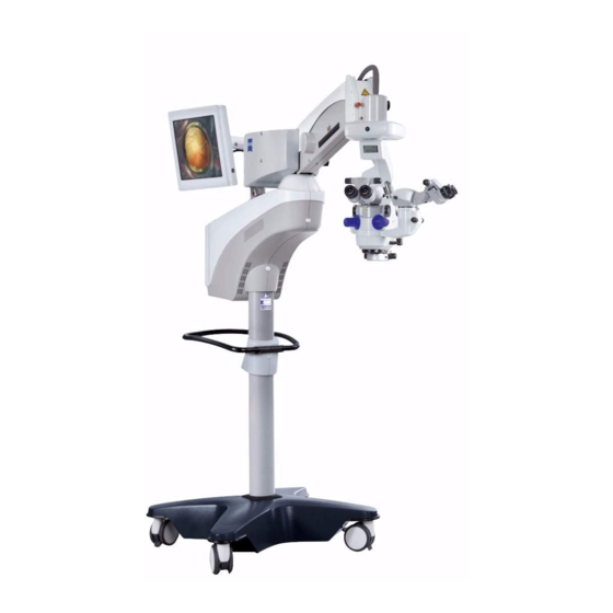
Instructions for Use 3 Description of the device OPMI LUMERA 700 3.2 Device setup 3.2 Device setup Figure 1: Example with integrated CALLISTO eye Panel PC and assistant's microscope CALLISTO eye Panel PC (model II) Support arm for CALLISTO eye Panel PC... -
Page 36: Callisto Eye Panel Pc
3 Description of the device Instructions for Use 3.2 Device setup OPMI LUMERA 700 3.2.1 CALLISTO eye Panel PC The CALLISTO eye Panel PC provides hardware and interfaces for the device. This hardware enables the device to receive, record and play back video signals generated during surgery. -
Page 37: Lamp Housing
Instructions for Use 3 Description of the device OPMI LUMERA 700 3.2 Device setup 3.2.3 Lamp housing The lamp housing is used to store the light sources. Simple light sources supply light to the surgical microscope's SCI illumination system. Dual light sources supply light to the surgical microscope's SCI illumination system as well as an additional illumination system. - Page 38 3 Description of the device Instructions for Use 3.2 Device setup OPMI LUMERA 700 3.2.3.1 Light source features Feature Explanation Light source Superlux Halogen LED Lamp Manual Automat Automat change 3.2.3.2 Swivel filters Filter Explanation Light source Superlux Halogen LED...
-
Page 39: Suspension Arm
Instructions for Use 3 Description of the device OPMI LUMERA 700 3.2 Device setup 3.2.4 Suspension arm The suspension arm is used to position the microscope vertically and horizontally. Figure 6: Suspension arm Magnetic brake Cable tray XY coupling interface 3.2.5 XY coupling The XY coupling is used to orient the surgical microscope vertically above the patient's eye in the X and Y-direction. -
Page 40: Overhead Display
3 Description of the device Instructions for Use 3.2 Device setup OPMI LUMERA 700 3.2.6 Overhead display The overhead display displays information on the device's software settings. Figure 8: Overhead display Display 3.2.7 Surgical microscope The surgical microscope enlarges and illuminates the surgical field. - Page 41 Instructions for Use 3 Description of the device OPMI LUMERA 700 3.2 Device setup 3.2.7.1 Invertertube E The Invertertube E rotates inverted images into an upright position. Figure 10: Invertertube E Tube body Eyepiece mount Panning mechanism The Invertertube E can be electrically swiveled 110°.
-
Page 42: Assistant's Microscope
3 Description of the device Instructions for Use 3.2 Device setup OPMI LUMERA 700 3.2.7.3 Objective lens The apochromatic lens adjusts the surgical microscope to fit different operating distances. Figure 12: Objective lens Lens Fine screw threads 3.2.8 Assistant's microscope The assistant's microscope provides the assistant with the same image as that of the main operator. -
Page 43: 14-Function Foot Control Panel
Instructions for Use 3 Description of the device OPMI LUMERA 700 3.2 Device setup 3.2.9 14-function foot control panel The 14-function foot control panel is used to operate the device hands free. Figure 14: 14-function foot control panel Bracket Storage bracket The 14-function foot control panel is available in wireless (FCP WL) -
Page 44: Stand Column
3 Description of the device Instructions for Use 3.2 Device setup OPMI LUMERA 700 3.2.11 Stand column Figure 16: Stand column Cable holder Bracket for foot control panel Transport handle 3.2.12 Support arm with connector panel The support arm is used to orient the suspension arm horizontally and to store electronic components. -
Page 45: Integrated 22" Monitor
Instructions for Use 3 Description of the device OPMI LUMERA 700 3.2 Device setup 3.2.13 Integrated 22" monitor The integrated 22" monitor can be used for dual observation of the surgical procedure by sterile surgical staff. Figure 18: Integrated 22" monitor Display 3.2.14 Support arm for integrated 22"... -
Page 46: Instrument Tray
3 Description of the device Instructions for Use 3.2 Device setup OPMI LUMERA 700 3.2.15 Instrument tray The instrument tray is intended to hold ZEISS devices. Figure 20: Instrument tray Mount for integrated 22" Instrument support monitor 3.2.16 Integrated keratoscope ring The integrated keratoscope ring provides intraoperative visualiza- tions of corneal curvatures. -
Page 47: Connections On The Surgical Microscope
Instructions for Use 3 Description of the device OPMI LUMERA 700 3.2 Device setup 3.2.17 Connections on the surgical microscope Figure 22: Connections on the surgical microscope Right coobservation output Left coobservation output Light guide input RESIGHT 700 port Invertertube E port 3.2.18 Connections on the assistant's microscope... -
Page 48: Connector Panel
3 Description of the device Instructions for Use 3.2 Device setup OPMI LUMERA 700 3.2.19 Connector panel Figure 24: Connector panel (example with optional connections) USB port for HD video and USB service port image recording (optional) LAN 1 network connection Remote connection for... -
Page 49: Callisto Eye Panel Pc Connector Panel (Model I)
Instructions for Use 3 Description of the device OPMI LUMERA 700 3.2 Device setup YPbPr video output 3.2.21 CALLISTO eye Panel PC connector panel (model I) Figure 26: CALLISTO eye Panel PC connector panel (model I) Voltage connection COM port Microphone port USB ports (4x) -
Page 50: Control Elements And Displays
3 Description of the device Instructions for Use 3.3 Control elements and displays OPMI LUMERA 700 HDMI 1 port (for IDIS) HDMI 2 port USB ports (4x) LAN 2 network connection LUMERA 700 / hospital 10 CAN connector network LAN 1 network... -
Page 51: Halogen Light Source Fault Signal
Instructions for Use 3 Description of the device OPMI LUMERA 700 3.3 Control elements and displays 3.3.2 Halogen light source fault signal Figure 29: Halogen light source fault signal Item Symbol Name Explanation Automatic Flap open: halogen lamp is flap defective. The backup halogen lamp is on. -
Page 52: Manual Mode Fault Signal
3 Description of the device Instructions for Use 3.3 Control elements and displays OPMI LUMERA 700 3.3.4 Manual mode fault signal Figure 31: Manual mode fault signal Item Symbol Name Explanation Yellow LED Not illuminated: working mode is activated Illuminated yellow: manual mode is activated •... -
Page 53: Overhead Display
Instructions for Use 3 Description of the device OPMI LUMERA 700 3.3 Control elements and displays 3.3.5 Overhead display Figure 32: Displayable elements on the overhead display Item Symbol Name Explanation "CAUTION" Displays a message on the control panel. Once the message is... -
Page 54: Surgical Microscope
3 Description of the device Instructions for Use 3.3 Control elements and displays OPMI LUMERA 700 Item Symbol Name Explanation SCI illumi- Position 1: red reflex illumination nation mix 100%, surrounding field illumi- ratio nation 0%. Position 2: red reflex illumination 100%, surrounding field illumi- nation 50%. -
Page 55: Assistant's Microscope
Instructions for Use 3 Description of the device OPMI LUMERA 700 3.3 Control elements and displays Item Symbol Name Explanation [Coobser- Switches from left to right vation coobservation output or vice versa. output] rotary knob [SCI illumi- In the event of device fault: nation] manually switch SCI illumination. -
Page 56: Invertertube E
3 Description of the device Instructions for Use 3.3 Control elements and displays OPMI LUMERA 700 Item Symbol Name Explanation [Zoom] Rotate left: larger rotary knob Rotate right: smaller Locking Releases the lock on the assistant's button microscope. The button is always located opposite the assistant’s... -
Page 57: Widefield Eyepiece
Instructions for Use 3 Description of the device OPMI LUMERA 700 3.3 Control elements and displays 3.3.9 Widefield eyepiece Figure 36: Control elements on widefield eyepiece Item Name Explanation Diopter setting Compensates for visual defects from -8 dpt to ring +5 dpt. -
Page 58: 14-Function Foot Control Panel
3 Description of the device Instructions for Use 3.3 Control elements and displays OPMI LUMERA 700 3.3.11 14-function foot control panel Figure 38: Controls on the 14-function foot control panel Item Name Explanation Buttons Controls device functions (freely config- urable). Rocker switches Control zoom and focus (horizontal and vertical configuration possible). -
Page 59: Xy Coupling
Instructions for Use 3 Description of the device OPMI LUMERA 700 3.3 Control elements and displays 3.3.12 XY coupling Figure 39: XY coupling control elements Item Symbol Name Explanation XY reset Resets functions to their initial button positions. Not illuminated: the following... -
Page 60: Suspension Arm
3 Description of the device Instructions for Use 3.3 Control elements and displays OPMI LUMERA 700 3.3.13 Suspension arm Figure 40: Control elements on the suspension arm Item Symbol Name Explanation [Release Triggers the magnetic brake. Can magnetic be operated by unsterile persons. -
Page 61: Control Panel
Instructions for Use 3 Description of the device OPMI LUMERA 700 3.3 Control elements and displays 3.3.14 Control panel Figure 41: Control elements on the control panel Item Symbol Name Explanation [Manual Activates manual control. mode] switch Control Controls and configures the panel software. -
Page 62: Callisto Eye Panel Pc (Model I)
3 Description of the device Instructions for Use 3.3 Control elements and displays OPMI LUMERA 700 3.3.15 CALLISTO eye Panel PC (model I) Figure 42: Control elements on the CALLISTO eye Panel PC (model I) Item Symbol Name Explanation [Power] button Not illuminated: CALLISTO eye Panel PC is... -
Page 63: Callisto Eye Panel Pc (Model Ii)
Instructions for Use 3 Description of the device OPMI LUMERA 700 3.3 Control elements and displays 3.3.16 CALLISTO eye Panel PC (model II) Figure 43: Control elements on the CALLISTO eye Panel PC (model II) Item Symbol Name Explanation [Power] button Not illuminated: CALLISTO eye Panel PC is... -
Page 64: Superlux Eye Light Source
3 Description of the device Instructions for Use 3.3 Control elements and displays OPMI LUMERA 700 3.3.17 Superlux Eye light source Figure 44: Control elements on the Superlux Eye light source Item Symbol Name Explanation [Backup Switches to the backup xenon xenon lamp] lamp. -
Page 65: Software Description
Instructions for Use 3 Description of the device OPMI LUMERA 700 3.4 Software description 3.4 Software description 3.4.1 Structure of the operating panel The displayed elements consist of the operating panel functions. Figure 46: Structure of the operating panel Pos. Name... -
Page 66: Status Bar
3 Description of the device Instructions for Use 3.4 Software description OPMI LUMERA 700 Item Symbol Name Explanation System Saves device-specific values (e.g. optical settings, pairing, network, etc.) User name / Saves user-specific start Start values values. (e.g. SCI illumi- nation, zoom, etc.) -
Page 67: Color Code
Instructions for Use 3 Description of the device OPMI LUMERA 700 3.4 Software description 3.4.4 Color code The button colors provide information about the status of display elements or the functions they represent. Button Color Explanation Gray Locked button. Light blue Clickable button. - Page 68 3 Description of the device Instructions for Use 3.4 Software description OPMI LUMERA 700 Button Name Explanation Function button Activates a function. Adds an element. Delete Deletes a selected element. Edit Modifies a selected element. Workflow steps Opens the "Surgery Profiles"...
-
Page 69: Navigation Buttons
Instructions for Use 3 Description of the device OPMI LUMERA 700 3.4 Software description 3.4.6 Navigation buttons The following elements are used for navigating through menus: Button Name Explanation Menu button Opens a menu. Submenu button Opens a submenu. Selection field Opens a selection list. -
Page 70: Control Panel Keyboard
3 Description of the device Instructions for Use 3.4 Software description OPMI LUMERA 700 3.4.7 Control panel keyboard If text entries need to be made, a virtual keyboard is displayed on the control panel with the following input options: Figure 49: Control panel keyboard... -
Page 71: Settings For Daily Operation - Main Menu, Tab 1
Instructions for Use 3 Description of the device OPMI LUMERA 700 3.4 Software description 3.4.8 Settings for daily operation - main menu, tab 1 Figure 50: Main menu, tab 1 Item Symbol Name Explanation User Manages user and surgery profiles. Light Adjusts the SCI illumination and light sources. -
Page 72: Basic Device Settings - Main Menu, Tab 2
3 Description of the device Instructions for Use 3.4 Software description OPMI LUMERA 700 3.4.9 Basic device settings - main menu, tab 2 Figure 51: Main menu, tab 2 Item Symbol Name Explanation System Adjusts system-specific settings: Settings • Optics • Pairing •... -
Page 73: Factory Settings For Handgrips And 14-Function Foot Control Panel
Instructions for Use 3 Description of the device OPMI LUMERA 700 3.4 Software description 3.4.10 Factory settings for handgrips and 14-function foot control panel 3.4.10.1 Left handgrip factory settings Figure 52: Left handgrip preconfigured button assignments Item Symbol Name Explanation Release... - Page 74 3 Description of the device Instructions for Use 3.4 Software description OPMI LUMERA 700 3.4.10.2 Right handgrip factory settings Figure 53: Right handgrip preconfigured button assignments Item Symbol Name Explanation Release Direction of Releases all magnetic brakes and brakes rotation A allows the device to be moved along all axes.
- Page 75 Instructions for Use 3 Description of the device OPMI LUMERA 700 3.4 Software description 3.4.10.3 Factory settings for 14-function foot control panel Figure 54: Foot control panel preconfigured button assignments Item Symbol Name Explanation Light - Button A Reduces the light intensity of the main light source.
-
Page 76: Configurable Assignments For Handgrips And The 14-Function Foot Control Panel
3 Description of the device Instructions for Use 3.4 Software description OPMI LUMERA 700 3.4.11 Configurable assignments for handgrips and the 14- function foot control panel Area Function Explanation Assignment possible No function Button is disabled. Light/ Light On / Off... - Page 77 Instructions for Use 3 Description of the device OPMI LUMERA 700 3.4 Software description Area Function Explanation Assignment possible OPMI Focus + Raises the surgical microscope focus. Focus - Lowers the surgical microscope focus. RESIGHT focus + For RESIGHT user profile: raises the RESIGHT 700 focus.
- Page 78 3 Description of the device Instructions for Use 3.4 Software description OPMI LUMERA 700 Area Function Explanation Assignment possible Other DeepView On / Off Turns the overhead display on or off. Release brakes Releases all magnetic brakes and allows the device to be moved along all axes.
-
Page 79: Functional Description
Instructions for Use 3 Description of the device OPMI LUMERA 700 3.5 Functional description 3.5 Functional description 3.5.1 Operating concept In order to ensure that the optimal device settings are available during different surgical phases, different surgery profiles can be created for each user. - Page 80 3 Description of the device Instructions for Use 3.5 Functional description OPMI LUMERA 700 Example: surgery profile configuration options User "Mustermann" Device setting Surgery profile for Surgery profile for Surgery profile for "Cataract surgery" "Retina surgery with "Retina surgery with RESIGHT"...
-
Page 81: Sci Illumination
Instructions for Use 3 Description of the device OPMI LUMERA 700 3.5 Functional description 3.5.2 SCI illumination SCI illumination (Stereo Coaxial Illumination) is used for illuminating the surgical field and generating a red reflex. SCI illumination features three preconfigured types of illumination, the mix ratio of which can be retrospectively adjusted. -
Page 82: Total Magnification
3 Description of the device Instructions for Use 3.5 Functional description OPMI LUMERA 700 Function Effect Light status The following status options are available: • [On]: OPMI light is switched on following activation of the device setting. • [Off]: OPMI light is switched off following activation of the device setting. -
Page 83: Resight Functions
Instructions for Use 3 Description of the device OPMI LUMERA 700 3.5 Functional description 3.5.6 RESIGHT functions The device can be equipped with the RESIGHT 500 or RESIGHT 700 contact-free fundus viewing systems. The fundus viewing system provides a detailed view of the retina without having to move the microscope. -
Page 84: Links
3 Description of the device Instructions for Use 3.5 Functional description OPMI LUMERA 700 Function Effect Reset focus Moves the OPMI focus and internal focus on the position RESIGHT 700 fundus viewing system (if connected) to their initial positions (center position). This setting cannot be deactivated. -
Page 85: Assistant's Microscope
Instructions for Use 3 Description of the device OPMI LUMERA 700 3.5 Functional description • Manually set the magnification on the microscope's zoom adjustment knob. • Manually position the suspension system for focusing and for moving the system in the XY direction. -
Page 86: Integrated Slit Illumination
3 Description of the device Instructions for Use 3.5 Functional description OPMI LUMERA 700 • RHEXIS : provides assistance when reaching the desired size and shape of the capsulorhexis. • Incision/LRI : an assistance function for positioning incisions and LRIs. -
Page 87: Integrated Hd Video And Image Recording
Instructions for Use 3 Description of the device OPMI LUMERA 700 3.5 Functional description • Automatic exposure adjusts the brightness of the video image to the specified nominal value automatically. • Manual exposure deactivates the exposure metering and sets a fixed exposure time. - Page 88 3 Description of the device Instructions for Use 3.5 Functional description OPMI LUMERA 700 Function Effect Video quality Saves video recordings at the following quality levels: • Low - suitable for documentation purposes • Medium - suitable for documentation purposes •...
-
Page 89: Installation
Local legis- lation has priority over the above normative requirements. Connect only devices which are approved by ZEISS or demon- strably comply with the applicable standards and directives (e.g. IEC 60950:2005 for data processing equipment). In... -
Page 90: Preparing The Installation
4 Installation Instructions for Use 4.2 Preparing the installation OPMI LUMERA 700 4.2 Preparing the installation 4.2.1 Requirements for connecting the device to an IT network The device can be connected to an existing IT network. This enables: • Video and image data to be saved to a shared directory. - Page 91 Instructions for Use 4 Installation OPMI LUMERA 700 4.2 Preparing the installation • The IT network to which the device is to be connected must have the following features: – IPv4, static or dynamic address. – Any IP address. • The IT network to which the device is to be connected must have the following configuration: –...
-
Page 92: Connections
4 Installation Instructions for Use 4.3 Connections OPMI LUMERA 700 4.3 Connections 4.3.1 Connecting the power supply 230 V 115 V Figure 55: Connecting the power supply Sliding switch for rated Power inlet socket voltage Potential equalization connector Risk of injury caused by electrical voltage! -
Page 93: Connecting The 14-Function Foot Control Panel
Instructions for Use 4 Installation OPMI LUMERA 700 4.3 Connections 4.3.2 Connecting the 14-function foot control panel The device can be controlled using either the wireless or wired variants of the foot control panel. 4.3.2.1 Connecting the wireless variant Action 1. -
Page 94: Setting Up A Network Connection With The Callisto Eye Panel Pc
4 Installation Instructions for Use 4.3 Connections OPMI LUMERA 700 4.3.3 Setting up a network connection with the CALLISTO eye Panel PC The device can be connected either directly (point to point) or indirectly via a switch to an external CALLISTO eye Panel PC. - Page 95 Instructions for Use 4 Installation OPMI LUMERA 700 4.3 Connections Risk of injury due to electrical current! CAUTION! In the event of a defect in the IT network, the network cable plug can carry dangerous voltage. Check to make sure that the requirements [} 90] for connecting the device to an IT network are met.
- Page 96 4 Installation Instructions for Use 4.3 Connections OPMI LUMERA 700 4.3.3.2 Setting up a direct network connection (without IT network connection) Figure 59: Network connection with CALLISTO eye Panel PC (model I) Figure 60: Network connection with CALLISTO eye Panel PC (model II)
- Page 97 Instructions for Use 4 Installation OPMI LUMERA 700 4.3 Connections ð The CALLISTO eye Panel PC network adapter is now activated and visible for the device. 5. Switch the device on. 6. Turn the CALLISTO eye Panel PC on. 7. Configure the network connection with CALLISTO eye. [} 142]...
-
Page 98: Setting Up A Network Connection With Integrated Callisto Eye Panel Pc
4 Installation Instructions for Use 4.3 Connections OPMI LUMERA 700 4.3.4 Setting up a network connection with integrated CALLISTO eye Panel PC The device can be connected either directly (point to point) or indirectly via a switch to an integrated CALLISTO eye Panel PC. - Page 99 Instructions for Use 4 Installation OPMI LUMERA 700 4.3 Connections 4.3.4.2 Setting up a direct connection (without IT network connection) Figure 62: Setting up a direct connection LAN 2 network connection LAN 1 network connection Material • Patch cable Action 1. Connect the LAN 1 network connector to the LAN 2 network connector.
-
Page 100: Connecting Idis Via Callisto Eye Panel Pc
4 Installation Instructions for Use 4.3 Connections OPMI LUMERA 700 4.3.5 Connecting IDIS via CALLISTO eye Panel PC In order to use IDIS, you must connect the device to the CALLISTO eye Panel PC. Figure 63: IDIS with CALLISTO eye Panel PC (model I) Figure 64: IDIS with CALLISTO eye Panel PC (model II) - Page 101 Instructions for Use 4 Installation OPMI LUMERA 700 4.3 Connections þ To load the assistance functions, a video signal from the Prerequisite integrated HD camera must be present in the CALLISTO eye Panel PC. Video signals of external cameras are not supported...
-
Page 102: Connecting External Video Devices
4 Installation Instructions for Use 4.3 Connections OPMI LUMERA 700 4.3.6 Connecting external video devices External video devices can be connected to devices with an integrated HD camera. If the device is not equipped with integrated HD video and image recording, you can connect the optional MEDIALINK 100 SD video recording tool. - Page 103 Instructions for Use 4 Installation OPMI LUMERA 700 4.3 Connections 4.3.6.2 Connecting the MEDIALINK 100 and SD monitor to the integrated HD camera Figure 66: Connecting the SD monitor via MEDIALINK Y/C video output (green) MEDIALINK 100 connector panel Risk of injury caused by accessories falling down!
-
Page 104: Connecting The Strain Relief
4 Installation Instructions for Use 4.3 Connections OPMI LUMERA 700 4.3.7 Connecting the strain relief The strain relief protects the cables against being pulled out. Action 1. Form a loop with the cable. Length of cable between strain relief and connector: at least 320 mm 2. -
Page 105: Daily Startup
Instructions for Use 5 Daily startup OPMI LUMERA 700 5.1 Outfitting the surgical and assistant's microscopes with accessories 5 Daily startup 5.1 Outfitting the surgical and assistant's microscopes with accessories 5.1.1 Replacing accessories and components Risk of injury caused by accessories falling down! - Page 106 5 Daily startup Instructions for Use 5.1 Outfitting the surgical and assistant's microscopes with accessories OPMI LUMERA 700 Material • Tubes and eyepieces for surgical and assistant's microscopes • Objective lens • As required: RESIGHT 500 or RESIGHT 700 fundus viewing system •...
- Page 107 Instructions for Use 5 Daily startup OPMI LUMERA 700 5.1 Outfitting the surgical and assistant's microscopes with accessories 5. Attach a tube to the main observer and turn the securing screw clockwise until it is tight. You can install further accessories between the tube and the main observer in the same way.
-
Page 108: Connecting The Invertertube E
5 Daily startup Instructions for Use 5.1 Outfitting the surgical and assistant's microscopes with accessories OPMI LUMERA 700 9. Adjust the parameters on the tube, objective lens and eyepieces. [} 139] 10. Additional accessories can be installed on the underside of the microscope. - Page 109 Instructions for Use 5 Daily startup OPMI LUMERA 700 5.1 Outfitting the surgical and assistant's microscopes with accessories 3. Secure the connection cable with a cable clip. To do this, push the cap out of the cable clip. 4. Form the connecting cable into a loop.
-
Page 110: Connecting Resight 700
5 Daily startup Instructions for Use 5.1 Outfitting the surgical and assistant's microscopes with accessories OPMI LUMERA 700 5.1.3 Connecting RESIGHT 700 The RESIGHT 700 internal focus is controlled by the electrical connection. If RESIGHT 700 is connected along with the Invertertube E, both accessories are synchronized and the field of view is always displayed in the correct orientation. -
Page 111: Balancing The System
Instructions for Use 5 Daily startup OPMI LUMERA 700 5.1 Outfitting the surgical and assistant's microscopes with accessories Action 1. Insert the end of the light guide as far as it will go into the light guide socket of the auxiliary illumination system. - Page 112 5 Daily startup Instructions for Use 5.1 Outfitting the surgical and assistant's microscopes with accessories OPMI LUMERA 700 2. Hold the suspension arm in position and gently pull the [Fixing suspension arm position] rotary knob out. If the rotary knob does not release, repeat step 1.
-
Page 113: Adjusting The Surgical And Assistant's Microscopes
Instructions for Use 5 Daily startup OPMI LUMERA 700 5.2 Adjusting the surgical and assistant's microscopes 5.2 Adjusting the surgical and assistant's microscopes 5.2.1 Adjusting the downward travel limit The downward travel limit limits the working distance from the surgical field. This prevents the surgical microscope from coming into contact with the patient if it is inadvertently lowered. -
Page 114: Adjusting Friction
5 Daily startup Instructions for Use 5.2 Adjusting the surgical and assistant's microscopes OPMI LUMERA 700 5.2.2 Adjusting friction The friction setting allows the surgical microscope to rotate left and right. Action 1. To increase mobility: rotate the friction knob counter clockwise. -
Page 115: Adjusting Microscope Tilt
Instructions for Use 5 Daily startup OPMI LUMERA 700 5.2 Adjusting the surgical and assistant's microscopes 5.2.4 Adjusting microscope tilt The manual tilting device can be used to orient the optical axis of the surgical microscope vertically to the patient's eye. -
Page 116: Adjusting The Tubes And Eyepieces
5 Daily startup Instructions for Use 5.2 Adjusting the surgical and assistant's microscopes OPMI LUMERA 700 5.2.5 Adjusting the tubes and eyepieces With the right settings, you can achieve an image which is sharply defined over the complete magnification range without any renewed focusing during the magnification setting. -
Page 117: Adjusting The Working Distance And Magnification
Instructions for Use 5 Daily startup OPMI LUMERA 700 5.2 Adjusting the surgical and assistant's microscopes 8. Follows steps 9 through 11 for each eyepiece individually. 9. Rotate the diopter adjustment ring on the eyepiece to its maximum plus diopter value. -
Page 118: Positioning The Device In The Or
5 Daily startup Instructions for Use 5.3 Positioning the device in the OR OPMI LUMERA 700 5.3 Positioning the device in the OR 5.3.1 Moving the device Figure 67: Moving the device Steerable caster Locking device Transport handle Risk of injury caused by inappropriate cable routing! CAUTION! May cause persons to trip and fall. -
Page 119: Swiveling The Device Over The Surgical Field
Instructions for Use 5 Daily startup OPMI LUMERA 700 5.3 Positioning the device in the OR 5.3.2 Swiveling the device over the surgical field Figure 68: Surgical situation (example with an assistant on the left-hand side) Support arm Sterilization nurse Surgeon... -
Page 120: Placing The Device In The Working Position
5 Daily startup Instructions for Use 5.3 Positioning the device in the OR OPMI LUMERA 700 5.3.3 Placing the device in the working position Figure 69: Placing the device in the working position Park position Working position Risk of injury caused by lowering of the surgical microscope! -
Page 121: Orienting The Integrated Callisto Eye Panel Pc
Instructions for Use 5 Daily startup OPMI LUMERA 700 5.3 Positioning the device in the OR 5.3.4 Orienting the integrated CALLISTO eye Panel PC Figure 70: Orienting the integrated CALLISTO eye Panel PC Fixing lever Monitor Suspension arm Risk of crushing caused by moving parts! CAUTION! Fingers may be crushed between the monitor and support arm. -
Page 122: Orienting The Integrated 22" Monitor
5 Daily startup Instructions for Use 5.3 Positioning the device in the OR OPMI LUMERA 700 5.3.5 Orienting the integrated 22" monitor Figure 71: Orienting the integrated 22" monitor 22" monitor Suspension arm Support arm Risk of crushing caused by moving parts! CAUTION! Fingers may be crushed between the monitor and support arm. -
Page 123: Before Every Use
Instructions for Use 6 Before every use OPMI LUMERA 700 6.1 Safety during preparation 6 Before every use 6.1 Safety during preparation Risk of injury caused by attached fundus viewing system! WARNING! Incorrect handling of a fundus viewing system mounted on the underside of the microscope, or activation of the fast focus, may cause injury to the patient’s eye. -
Page 124: Switching The Device On
The automatic circuit breaker in the power switch was activated due to a circuit overload or short. To switch the device on: press the power switch. If the automatic circuit breaker is triggered again, notify ZEISS Service. þ The 14-function foot control panel is connected. -
Page 125: Function Test
Instructions for Use 6 Before every use OPMI LUMERA 700 6.3 Function test 6.3 Function test Function tests reveal faults and incorrect software settings that may impact your work or result in unexpected device behavior. 6.3.1 Device function tests Use the following list to check device functionality before each use (patient should not be present!). -
Page 126: Function Tests For Device With Fundus Viewing System
6 Before every use Instructions for Use 6.3 Function test OPMI LUMERA 700 ð For xenon lamps: the remaining service hours must be suffi- cient to complete the operation. Check to make sure the objective lens and the eyepieces are clean. -
Page 127: Preparing The System For Sterile Use
Instructions for Use 6 Before every use OPMI LUMERA 700 6.4 Preparing the system for sterile use 6.4 Preparing the system for sterile use 6.4.1 Attaching sterile accessories Risk of infection caused by missing sterile accessories! CAUTION! The patient or user can become infected if sterile accessories are not used. - Page 128 6 Before every use Instructions for Use 6.4 Preparing the system for sterile use OPMI LUMERA 700 4. Slide the 49 mm sterilizable cap onto the [OPMI tilt] adjustment knob. 5. For 180° tiltable tube: slide the 49 mm sterilizable cap onto the [Interpupillary distance] adjustment knob.
-
Page 129: Placing The Drape
Instructions for Use 6 Before every use OPMI LUMERA 700 6.4 Preparing the system for sterile use 6.4.2 Placing the drape Figure 73: Placing the drape Objective lens Reduced image quality! NOTE Drapes with vision guard may reduce the image quality of the optics. - Page 130 Empty page, for your notes...
-
Page 131: Operation
Instructions for Use 7 Operation OPMI LUMERA 700 7.1 Safety during operation 7 Operation 7.1 Safety during operation Risk of injury due to electrical current! CAUTION! Contact with plug connector contacts may cause electric shock. Never touch the contacts on plug connectors during contact with the patient. -
Page 132: Configuring User And Surgery Profiles
7 Operation Instructions for Use 7.2 Configuring user and surgery profiles OPMI LUMERA 700 7.2 Configuring user and surgery profiles 7.2.1 Creating and activating users Upon first login, the predefined user Default User is set. The Default User cannot be deleted; it features the following characteristics: •... -
Page 133: Changing The User Language
Instructions for Use 7 Operation OPMI LUMERA 700 7.2 Configuring user and surgery profiles ð A message will appear: "The current user is being changed. Please wait." ü The user is displayed in the footer. Result 7.2.2 Changing the user language The "Default User"... -
Page 134: Creating A "Retina Resight" Surgery Profile
7 Operation Instructions for Use 7.2 Configuring user and surgery profiles OPMI LUMERA 700 ð The user menu will appear. 3. Select the "Anterior" surgery profile. To do this, tap the button next to the "Surgery profile" selection field. ð The screen keyboard will appear. -
Page 135: Creating A "Retina Contact" Surgery Profile
Instructions for Use 7 Operation OPMI LUMERA 700 7.2 Configuring user and surgery profiles 3. Select the "Posterior" surgery profile. To do this, tap the button next to the "Surgery profile" selection field. ð The screen keyboard will appear. 4. Delete the name and replace it with "Retina RESIGHT". The name can be no longer than 20 characters. -
Page 136: Assigning The Resight Function To The Surgery Profile
7 Operation Instructions for Use 7.2 Configuring user and surgery profiles OPMI LUMERA 700 3. Activate the "Retina RESIGHT" surgery profile. 4. To add the "Retina Contact" surgery profile: tap the button next to the "Surgery profile" selection field. ð The screen keyboard will appear. -
Page 137: Configuring Working Steps
Instructions for Use 7 Operation OPMI LUMERA 700 7.2 Configuring user and surgery profiles Action 1. Open the main menu. 2. Open the [User] menu. 3. Tap the button. ð The "Surgery profile" menu will appear. 4. Select the desired device settings. -
Page 138: Deleting A Surgery Profile
7 Operation Instructions for Use 7.3 Device-specific software configuration OPMI LUMERA 700 4. Select the device setting you would like to move. ð The selected device setting features a light gray background. 5. Adjust the order of device settings with the arrow buttons. -
Page 139: Configuring Optics
Instructions for Use 7 Operation OPMI LUMERA 700 7.3 Device-specific software configuration • Switching from summer to winter time, or vice versa þ No surgical operation is currently in progress. Changing the Prerequisite date or time requires restarting the device! Action 1. -
Page 140: Pairing
7 Operation Instructions for Use 7.3 Device-specific software configuration OPMI LUMERA 700 4. Select the eyepiece and the objective lens the device is using. ð Activated functions are illuminated blue. 5. To save the settings for a specific device: tap the [System] button. -
Page 141: Configuring The Video Signal Of The Integrated Hd Camera
Instructions for Use 7 Operation OPMI LUMERA 700 7.3 Device-specific software configuration 6. Perform a function test. To do this, press any two buttons on the foot control panel. ð The "Radio link intensity" status indicator will illuminate green for approximately one second. -
Page 142: Configuring The Network Connection With Callisto Eye
7 Operation Instructions for Use 7.3 Device-specific software configuration OPMI LUMERA 700 ð The "Video format" menu will appear. 4. Select the desired display format. 5. To save the settings for a specific device: tap the [System] button. 7.3.5 Configuring the network connection with CALLISTO eye There are two ways to establish a network connection: •... - Page 143 Instructions for Use 7 Operation OPMI LUMERA 700 7.3 Device-specific software configuration 5. To automatically provide network parameters: activate the [DHCP] button. ð The button will turn blue. ð The "IP address", "Subnet mask" and "Gateway" buttons will become deactivated.
-
Page 144: Configuring Integrated Hd Video And Image Recording
7 Operation Instructions for Use 7.3 Device-specific software configuration OPMI LUMERA 700 3. Enter the CALLISTO eye IP address. Only numeric entries with the following syntax are possible: <No.>.<No.>.<No.>.<No.> (ranging between 0 and 255). 4. To save the IP address: tap the button. - Page 145 Instructions for Use 7 Operation OPMI LUMERA 700 7.3 Device-specific software configuration 7.3.6.1 Configuring the network connection The network connection for integrated HD video and image recording can be established manually or automatically via a DHCP server. þ The device is connected to an IT network via a network cable.
-
Page 146: Configuring The Software For Specific Users
7 Operation Instructions for Use 7.4 Configuring the software for specific users OPMI LUMERA 700 10. To save the IP address: tap the button. ð The "Recording Network" menu will appear. 11. Follow the same steps for "Subnet mask" and "Gateway". -
Page 147: Configuring The 14-Function Foot Control Panel
Instructions for Use 7 Operation OPMI LUMERA 700 7.4 Configuring the software for specific users 7.4.1 Configuring the 14-function foot control panel The 14-function foot control panel's buttons and rocker switches can be assigned user-specific functions [} 76]. If the RESIGHT 700 is... -
Page 148: Configuring Image Inversion On The Invertertube E
7 Operation Instructions for Use 7.4 Configuring the software for specific users OPMI LUMERA 700 Action 1. Open the main menu. 2. Tap the [Additional Settings] menu button. 3. Tap the [Handgrip] submenu button. ð The "Left Handgrip" menu will appear. -
Page 149: Configuring The Direction Of The Xy Coupling
Instructions for Use 7 Operation OPMI LUMERA 700 7.4 Configuring the software for specific users 4. Tap the selection field under "Image orientation". ð The image statuses will appear. 5. To turn on inversion: tap the [Invert] button. 6. Activate the modified image. Tap the button and confirm the prompt. -
Page 150: Configuring The Overhead Display
7 Operation Instructions for Use 7.4 Configuring the software for specific users OPMI LUMERA 700 þ The surgery profile you wish to configure is activated. Prerequisite Action 1. Open the main menu. 2. Tap the [Additional Settings] menu button. 3. Tap the [RESIGHT] submenu button. -
Page 151: Configuring Links
Instructions for Use 7 Operation OPMI LUMERA 700 7.4 Configuring the software for specific users Risk of injury caused by attached fundus viewing system! WARNING! Incorrect handling of a fundus viewing system mounted on the underside of the microscope, or activation of the fast focus, may cause injury to the patient’s eye. -
Page 152: Configuring Reset Options
7 Operation Instructions for Use 7.5 Daily operation OPMI LUMERA 700 5. To save the changes to the surgery profile: tap the button. 7.4.10 Configuring reset options The reset options [} 83] are basic settings that the device reverts back to when the XY reset button is pressed on the OPMI or the device is in the park position. -
Page 153: Setting The Illumination
Instructions for Use 7 Operation OPMI LUMERA 700 7.5 Daily operation Doing this overwrites the existing user profile or surgery profile (unless the factory default profile, "Default User", is currently active). If you do not want to overwrite the current user profile or surgery profile, you must first select and activate a different user profile or surgery profile. - Page 154 Use the lowest brightness setting possible. Select an appropriate brightness setting according to the recommended values provided by ZEISS (see "Maximum radiation exposure times" [} 27]). Doing this limits the exposure intensity and the exposure time.
- Page 155 Before each use, check each light source to make sure it is functioning properly. LED light source: If the fault signal is illuminated, the light source is defective, and the light intensity is 50%. Inform ZEISS Service. Xenon light source: If the fault signal is illuminated, the xenon lamp is defective, and the backup xenon lamp is in use.
- Page 156 7 Operation Instructions for Use 7.5 Daily operation OPMI LUMERA 700 3. Check the remaining service hours. 4. If the remaining service life is less than 5 hours, the backup xenon lamp must be swiveled in and the remaining service hours reset.
-
Page 157: Setting The Total Magnification
Instructions for Use 7 Operation OPMI LUMERA 700 7.5 Daily operation ð The selected submenu will appear. 4. Tab 2: Select a filter. 5. To temporarily save the settings: tap the button. 6. To save the settings to the surgery profile: tap the button. -
Page 158: Setting Deepview
7 Operation Instructions for Use 7.5 Daily operation OPMI LUMERA 700 2. Tap the [XY focus magnification] button. ð The "XY Focus Magnification" menu will appear. 3. Set the total magnification with the arrow buttons. 4. To temporarily change the settings: tap the button. -
Page 159: Setting The Focus Distance
Instructions for Use 7 Operation OPMI LUMERA 700 7.5 Daily operation 5. To temporarily change the settings: tap the button. 6. To save the settings to the surgery profile: tap the button. 7.5.4 Setting the focus distance The focus can be set between -30 mm and +40 mm in 1 mm incre- ments. -
Page 160: Setting The Integrated Keratoscope Ring
7 Operation Instructions for Use 7.5 Daily operation OPMI LUMERA 700 4. Use the arrow buttons to position the XY coupling. ð The XY coupling will immediately move in the corre- sponding direction. If the video image on the monitor... -
Page 161: Setting The Hd Digizoom
Instructions for Use 7 Operation OPMI LUMERA 700 7.5 Daily operation 5. Use the arrow buttons to set the desired light intensity. 6. To temporarily save the changes: tap the button. 7.5.7 Setting the HD Digizoom The camera image can be digitally magnified from 1.0x to 2.0x in 0.1 increments. - Page 162 7 Operation Instructions for Use 7.5 Daily operation OPMI LUMERA 700 þ The light source is on. þ The filters are swiveled in or out. þ IDIS is off. Action 1. Open the main menu. 2. Tap the [Camera] menu button.
- Page 163 Instructions for Use 7 Operation OPMI LUMERA 700 7.5 Daily operation Parameter Symbol Effect Large spot The exposure is measured in an area in the image center. This light metering method is ideal for surgical fields with darkened edges. Small spot The exposure is measured in a very small area in the image center.
- Page 164 7 Operation Instructions for Use 7.5 Daily operation OPMI LUMERA 700 7.5.8.3 Setting manual exposure control Manual exposure deactivates the exposure metering and sets a fixed exposure time. The exposure time can be set to any value between 1/10000 s and 1/8 s. An exposure time in the range between 1/50 and 1/30 usually provides optimum exposure results.
-
Page 165: Recording
Instructions for Use 7 Operation OPMI LUMERA 700 7.5 Daily operation 6. Use the arrow buttons to change the color values for Red value, Blue value and Peak / Average. 7. To temporarily save the settings: tap the button. 8. To save the settings to the surgery profile: tap the button. - Page 166 7 Operation Instructions for Use 7.5 Daily operation OPMI LUMERA 700 4. If required: create a patient file. To do this, tap the button. ð The "Recording" menu will appear. 5. Create a patient file under the last and first name of the patient.
- Page 167 Instructions for Use 7 Operation OPMI LUMERA 700 7.5 Daily operation 3. Start the video recording: tap the button. ð "REC" will appear in the status bar. The date and time are not displayed while video recording is in progress.
- Page 168 7 Operation Instructions for Use 7.5 Daily operation OPMI LUMERA 700 3. Take a photo: tap the button. ð The photo will be saved. ð You will hear an acoustic signal. 7.5.9.4 Viewing HD videos False diagnosis due to video images!
- Page 169 Instructions for Use 7 Operation OPMI LUMERA 700 7.5 Daily operation 3. Open the file directory. To do this, tap the [Change] button. ð The file directory will open and the available HD videos and photos will be displayed. 4. Select an HD video. To do this, tap the button.
- Page 170 7 Operation Instructions for Use 7.5 Daily operation OPMI LUMERA 700 7.5.9.5 Viewing photos False diagnosis due to video images! CAUTION! The monitors are neither calibrated nor designed for diagnostic purposes. Visualized images may contain variations in shape, contrast and color.
- Page 171 Instructions for Use 7 Operation OPMI LUMERA 700 7.5 Daily operation 6. To view a photo: Tap the button. 7. To switch between photos: tap the buttons. 8. To skip to the first or last photo: tap the buttons. 9. To stop viewing photos: tap the button.
-
Page 172: Transferring Control To Callisto Eye
7 Operation Instructions for Use 7.5 Daily operation OPMI LUMERA 700 3. Tap the [Change] button to the right of the file. ð The file folder will appear. 4. To delete an HD video: tap the button. To delete a photo: tap the button. -
Page 173: Ending Control Via Callisto Eye
Instructions for Use 7 Operation OPMI LUMERA 700 7.5 Daily operation 2. Tap the [CALLISTO Connection] menu button. ð The "CALLISTO eye" menu will appear. 3. To transfer control to CALLISTO eye: tap the [Allow] button. ð The following message will appear: "Info - The system is enabled for remote control / Active connection x.x.x.x."... -
Page 174: Typical Operating Sequence
7 Operation Instructions for Use 7.6 Typical operating sequence OPMI LUMERA 700 7.6 Typical operating sequence 7.6.1 Starting work Risk of injury caused by lowering of the external focus! CAUTION! If the foot control panel buttons are pressed unintentionally, the external focus of the surgical microscope may be lowered and injure the patient. -
Page 175: Carrying Out The Working Steps
Instructions for Use 7 Operation OPMI LUMERA 700 7.6 Typical operating sequence 7.6.2 Carrying out the working steps User "Dr. Mustermann" Surgery profile Surgery profile Surgery profile "Retina RESIGHT" "Retina Contact" "Cataract" Swivel RESIGHT 700 into position Swivel RESIGHT 700 out of position or press "Profile +"... -
Page 176: Switching The Device Off
7 Operation Instructions for Use 7.7 Switching the device off OPMI LUMERA 700 ð Depending on how the reset options [} 152] are configured, certain functions will be reset to their start values. 2. Switch the device off. 7.7 Switching the device off Figure 75: Switching the device off (example with integrated CALLISTO... -
Page 177: Cleaning And Disinfection
TIP: For regular cleaning of the surgical microscope’s objective lenses and eyepieces, we recommend using the optics cleaning kit available from ZEISS (Order no.: 1216-071). 8.2.2 Cleaning mechanical surfaces All mechanical surfaces of the system can be cleaned by wiping them with a damp cloth. -
Page 178: Disinfection
8 Cleaning and disinfection Instructions for Use 8.3 Disinfection OPMI LUMERA 700 An anti-fogging agent does not ensure fog-free eyepiece optics. It cleans eyepiece optics and protects them against dirt, grease, dust, lint and fingerprints. 8.3 Disinfection 8.3.1 Disinfection of surfaces The maximum application concentrations are: •... -
Page 179: Maintenance
Instructions for Use 9 Maintenance OPMI LUMERA 700 9.1 Maintenance schedule for the operator 9 Maintenance 9.1 Maintenance schedule for the operator 9.1.1 Every six months Component Activity Manual mode Check the following functions: • The light sources are at medium intensity •... - Page 180 9 Maintenance Instructions for Use 9.2 Maintenance schedule for the authorized service OPMI LUMERA 700 Component Activity Support system and Check the following functions: microscope suspension • The bearings, stops and suspension mounting mountings are free of play. • Brakes are operational at maximum permissible OPMI configuration.
-
Page 181: Every Two Years
Instructions for Use 9 Maintenance OPMI LUMERA 700 9.3 Performing safety inspections 9.2.3 Every two years Component Activity Light guide Check to make sure: • The light guide is intact. • The light field is uniform. Light source Check to make sure the light source filters are intact. - Page 182 9 Maintenance Instructions for Use 9.3 Performing safety inspections OPMI LUMERA 700 Risk of injury without safety inspection! CAUTION! Hazards and device deficiencies will not be detected in time and can have a negative effect on patients, users, or others.
-
Page 183: Troubleshooting
Instructions for Use 10 Troubleshooting OPMI LUMERA 700 10.1 Localizing malfunctions 10 Troubleshooting 10.1 Localizing malfunctions If a malfunction occurs, the corresponding information is displayed on the touchscreen in the form of a message. Malfunctions are saved to a log file which can be exported and forwarded to ZEISS. -
Page 184: Faults (With Messages)
If the error impairs electronics Activate manual mode. your work, please switch to manual Software error, inadmissible mode and contact your ZEISS service status of motor control representative. Light source error. The error can be Malfunction of light intensity If the error impairs your work: acknowledged. -
Page 185: Faults (Without Messages)
System error. The error can be Unknown software or Acknowledge the error acknowledged. If the error recurs, hardware error. message. please contact your ZEISS service If the message appears again, representative. contact ZEISS Service. 10.3 Faults (without messages) 10.3.1 Device faults... - Page 186 10 Troubleshooting Instructions for Use 10.3 Faults (without messages) OPMI LUMERA 700 Fault Cause Remedy Illumination on the surgical Brightness level set too low. Increase the brightness on the microscope is faulty. stand or on the 14-function foot control panel.
-
Page 187: Integrated Hd Video And Image Recording Faults
Instructions for Use 10 Troubleshooting OPMI LUMERA 700 10.3 Faults (without messages) Fault Cause Remedy Image on video monitor is too dark, Insufficient light. Increase the brightness level of or there is a high level of noise. the illumination. Incorrect light metering Activate the "Integral"... -
Page 188: 14-Function Foot Control Panel Faults
10 Troubleshooting Instructions for Use 10.3 Faults (without messages) OPMI LUMERA 700 Fault Cause Remedy Data cannot be displayed or played Non-supported file format Use supported file formats. back. imported or saved to the LAN. Video with incorrect video Set the device to the video... -
Page 189: Wired 14-Function Foot Control Panel Faults
Instructions for Use 10 Troubleshooting OPMI LUMERA 700 10.3 Faults (without messages) Fault Cause Remedy Functions are being triggered A button on the 14-function Place the 14-function foot unintentionally. foot control panel has become control panel in its rest position. -
Page 190: Troubleshooting Work
10 Troubleshooting Instructions for Use 10.4 Troubleshooting work OPMI LUMERA 700 10.4 Troubleshooting work 10.4.1 Activating manual mode Figure 77: Activating manual mode [Manual mode] switch Risk of injury caused by malfunctioning motor electronics! CAUTION! In the case of malfunctioning motor electronics, the device may make uncontrollable movements or main functions such as XY movement, focus, zoom and light control may become impaired. -
Page 191: Operating The Device In Manual Mode
Instructions for Use 10 Troubleshooting OPMI LUMERA 700 10.4 Troubleshooting work 10.4.2 Operating the device in manual mode Figure 78: Operating the device in manual mode Zoom adjustment knob [SCI illumination] rotary knob [Integrated slit illumination] rotary knob þ Manual mode is activated. -
Page 192: Changing The Halogen Lamp
10 Troubleshooting Instructions for Use 10.4 Troubleshooting work OPMI LUMERA 700 10.4.3 Changing the halogen lamp Figure 79: Changing the halogen lamp [Open lamp module] button Lamp module Lamp reflector of the Lamp bulb of the halogen halogen lamp lamp Ceramic base of the lamp module... -
Page 193: Swiveling The Backup Xenon Lamp Into Position And Resetting The Remaining Service Hours
If the lamp module is blocked or illumination is no longer operable, the device may not be used any longer. Contact ZEISS Service. þ The power switch is off. -
Page 194: Changing The Superlux Eye Light Source Lamp Module
10 Troubleshooting Instructions for Use 10.4 Troubleshooting work OPMI LUMERA 700 ð The following message will appear on the control panel: "OPMI light source: spare lamp is in use, please change main lamp." 6. Acknowledge the error message. 7. Reset the remaining service hours counter to its initial value of 500. -
Page 195: Setting The Gas Spring On The Integrated 22" Monitor
If the lamp module is blocked or illumination is no longer operable, the device may not be used any longer. Contact ZEISS Service. Material • Xenon backup lamp module with 2 xenon lamps for Superlux Eye þ... -
Page 196: Increasing Mobility Of The Suspension Arm On The Integrated 22" Monitor
10 Troubleshooting Instructions for Use 10.4 Troubleshooting work OPMI LUMERA 700 If the suspension arm continues to lower on its own, the gas spring is defective. 3. Inform ZEISS Service! 10.4.7 Increasing mobility of the suspension arm on the integrated 22" monitor If the 22"... -
Page 197: Increasing Mobility Of The Monitor Mount On The Integrated 22" Monitor
Instructions for Use 10 Troubleshooting OPMI LUMERA 700 10.4 Troubleshooting work 5. Reattach the plastic cover. 10.4.8 Increasing mobility of the monitor mount on the integrated 22" monitor If the 22" monitor is making undesired tilting movements, the mobility of the monitor mount can be increased. -
Page 198: Establishing Cable Connections For The 14-Function Foot Control Panel
4. To view all firmware versions: tap the arrow buttons. ð The menu will scroll up or down. 10.4.12 Opening the service menu The service menu is password-protected and may only be accessed by personnel trained by ZEISS. þ The service PIN is available Prerequisite Action 1. - Page 199 Instructions for Use 10 Troubleshooting OPMI LUMERA 700 10.4 Troubleshooting work 2. Tap the [System Settings] menu button. 3. Tap the [Service PIN] submenu button. ð The "Service PIN" menu will appear. 4. To open the service menu: enter the service PIN.
- Page 200 Empty page, for your notes...
-
Page 201: Technical Specifications
The device does not have any essential performance features as defined in IEC 60601-1. 11.2 Compliance Guidelines with which the device complies • OPMI LUMERA 700 complies with Medical Device Directive 93/42/EEC: Class I It is labeled with • This device satisfies the US American and Canadian safety regulations for medical electrical devices/systems. -
Page 202: Electrical Data
11 Technical specifications Instructions for Use 11.3 Electrical data OPMI LUMERA 700 11.3 Electrical data 11.3.1 Stand Values Rated voltage (115): 100 - 125 V AC (230): 220 - 240 V AC Total current consumption at 115 V 1200 VA maximum Total current consumption at 230 V 1200 VA maximum... -
Page 203: Integrated Hd Camera
Instructions for Use 11 Technical specifications OPMI LUMERA 700 11.3 Electrical data 11.3.3 Integrated HD camera Unit HD ready Full HD Full HD with video recording and streaming 1-Chip HD camera 1/3" progressive HD MOS sensor image sensor 3-Chip HD camera Three 1/3"... -
Page 204: Integrated Hd Video And Image Recording
11 Technical specifications Instructions for Use 11.3 Electrical data OPMI LUMERA 700 Unit HD ready Full HD Full HD with video recording and streaming YPbPr Pixels / Hz (PAL) 720p / 50 720p / 50 720p / 50 (-1.0 Vp-p/75 Ω (Y)) -
Page 205: Integrated Keratoscope Ring
Instructions for Use 11 Technical specifications OPMI LUMERA 700 11.4 Mechanical data 11.3.5 Integrated keratoscope ring Value Wavelength 610 nm (±15 nm) Radiation output 0.149 mW Divergence of beam (opening angle) 100° 11.3.6 Integrated 22" monitor Value Input voltage 12 V DC (± 10%) Current consumption < 5 A DC... -
Page 206: Optical Data
11 Technical specifications Instructions for Use 11.5 Optical data OPMI LUMERA 700 Value Screen diagonal 22" 11.5 Optical data 11.5.1 Surgical microscope Value Magnification (with objective lens f=200 3.5x - 21x and eyepiece 10x) Magnification factor 0.4x - 2.4x Zoom system... -
Page 207: Dimensions And Weights
Instructions for Use 11 Technical specifications OPMI LUMERA 700 11.6 Dimensions and weights 11.6 Dimensions and weights 11.6.1 Dimensions and swiveling ranges Figure 82: Dimensions and swiveling ranges Item Value Extension arm swiveling angle 320° Extension arm length 450 mm Suspension arm swiveling angle 320°... -
Page 208: Support Arm For Integrated Callisto Eye Panel Pc
11 Technical specifications Instructions for Use 11.6 Dimensions and weights OPMI LUMERA 700 11.6.2 Support arm for integrated CALLISTO eye Panel PC Figure 83: Dimensions and swiveling ranges Item Value Monitor mount swiveling angle 220° Monitor mount length 101 mm 70 mm Support arm tilt angle 45°... -
Page 209: Support Arm For Integrated 22" Monitor
Instructions for Use 11 Technical specifications OPMI LUMERA 700 11.6 Dimensions and weights 11.6.3 Support arm for integrated 22" monitor Figure 84: Dimensions and swiveling ranges Item Value Monitor mount swiveling angle 180° Monitor mount length 84 mm Suspension arm tilt angle ±41°... -
Page 210: Maximum Weight Capacity
11 Technical specifications Instructions for Use 11.6 Dimensions and weights OPMI LUMERA 700 11.6.4 Maximum weight capacity Figure 85: Maximum weight capacity Item Value Support arm for integrated 22" monitor 10kg. Support arm for integrated CALLISTO eye 15 kg Panel PC... -
Page 211: Ambient Requirements For Operation
Facility Environment. In order to avoid the occurrence of EMC disturbances, the device may only be installed, started up and maintained in the manner indicated in these Instructions for Use and only with components supplied by ZEISS. Malfunction caused by other devices! WARNING! Do not install or operate the OPMI LUMERA 700 in direct proximity... - Page 212 11 Technical specifications Instructions for Use 11.9 Guidance and manufacturer´s declaration – electromagnetic immunity OPMI LUMERA 700 Loss of performance caused by HF units! WARNING! Do not use any portable or mobile HF communication equipment or transmitters (including peripheral devices such as antenna cables or external antennas) in the proximity of the OPMI LUMERA 700 (minimum distance 30 cm).
-
Page 213: Emc - Electromagnetic Compatibility Iec 60601-1-2
Instructions for Use 11 Technical specifications OPMI LUMERA 700 11.9 Guidance and manufacturer´s declaration – electromagnetic immunity 11.9.1 EMC - electromagnetic compatibility IEC 60601-1-2 11.9.1.1 Electromagnetic disturbance emissions The OPMI LUMERA 700 is intended for operation in an electromagnetic environment as specified below. The customer or the user of the OPMI LUMERA 700 is responsible for ensuring that the device is operated in such... - Page 214 11 Technical specifications Instructions for Use 11.9 Guidance and manufacturer´s declaration – electromagnetic immunity OPMI LUMERA 700 Magnetic field for supply 30 A/m 30 A/m frequency (50/60 Hz) as per IEC 61000-4-8 Voltage dips, short interruptions 0% U for 1/2 cycle...
-
Page 215: Accessories And Spare Parts
A current list of accessories can be obtained from your ZEISS contact partner. You can find the ZEISS contact partner for your country on the following website: www.zeiss.com/med Use only accessories and spare parts which are approved by ZEISS for this device. -
Page 216: Sterilizable Caps
S light guide 2.0 m 303481-9020-000 S light guide 2.5 m 303481-9025-000 12.2.2 Dust cover Designation Specification Order no. Dust cover, blue, with ZEISS logo 000000-1055-278 12.2.3 Network cable Designation Specification Order no. Network cable 2x RJ45, 10 m 305946-8660-000 216 / 236... -
Page 217: Country-Specific Power Cable
Instructions for Use 12 Accessories and spare parts OPMI LUMERA 700 12.3 Components Designation Specification Order no. Patch cable 000000-2142-522 12.2.4 Country-specific power cable Designation Specification Order no. Europe 000000-0301-997 000000-0400-264 Switzerland 309850-9011-000 Argentina 000000-0434-527 Brazil 000000-0527-730 China 000000-0475-507 12.3 Components 12.3.1 Tubes for surgical and assistant's microscopes... -
Page 218: Objective Lenses
12 Accessories and spare parts Instructions for Use 12.3 Components OPMI LUMERA 700 12.3.4 Objective lenses Designation Specification Order no. Objective lens f = 200 mm 302652-9905-000 Objective lens f = 175 mm 302651-9905-000 Objective lenses with support ring f = 175 mm... -
Page 219: Callisto Eye
• Network cable • 10 m 302755-8641-000 12.4 UC kits The following UC kits (upgrade components) are integrated either in or on the device and must be installed by ZEISS Service after acquisition. G-30-1673-en - 14.0 - 2018-07-12 219 / 236... - Page 220 12 Accessories and spare parts Instructions for Use 12.4 UC kits OPMI LUMERA 700 Designation Specification Order no. UC kit, Superlux Eye light source Retrofit of a Superlux Eye light source for 304977-9027-500 halogen/Superlux Eye or LED/Superlux Eye dual light source.
-
Page 221: Decommissioning
Instructions for Use 13 Decommissioning OPMI LUMERA 700 13.1 Cleaning before storage 13 Decommissioning 13.1 Cleaning before storage 13.1.1 Cleaning the device and accessories Action Clean the device and any accessories which are no longer needed as described in "Cleaning and disinfection [} 177]". - Page 222 Empty page, for your notes...
-
Page 223: Packaging And Transport
Instructions for Use 14 Packaging and transport OPMI LUMERA 700 14.1 Preparing for transport 14 Packaging and transport 14.1 Preparing for transport 14.1.1 Placing the device in the transport position Risk of crushing caused by rotating support and suspension CAUTION! - Page 224 14 Packaging and transport Instructions for Use 14.1 Preparing for transport OPMI LUMERA 700 4. For integrated 22" monitor: place the integrated 22" monitor in the following transport position. 5. Feed the supplied Velcro tape through the bracket on the 22"...
-
Page 225: Disposal
For more information about the disposal of the device, please contact the ZEISS contact partner in your country. You can find the ZEISS contact partner for your country on the following website: www.zeiss.com/med If you want to sell the device or its components: Inform the purchaser that they must dispose of the device according to the regulations valid at that time. - Page 226 Empty page, for your notes...
-
Page 227: Glossary
Instructions for Use Glossary OPMI LUMERA 700 Glossary Automatic fuse Electromagnetic compatibility (EMC) An overcurrent protection device which EMC (electromagnetic compatibility) desig- switches the system off in the event of a nates the usually desired state in which short. technical devices do not impede each other by undesired electric or electromagnetic effects (non-interference). - Page 228 Glossary Instructions for Use OPMI LUMERA 700 K TRACK RHEXIS A CALLISTO eye assistance function used A CALLISTO eye assistance function which together with the keratoscope to visualize provides assistance when reaching the the corneal curvature. desired size and shape of the capsulorhexis.
- Page 229 Instructions for Use Glossary OPMI LUMERA 700 Another term for S-Video; color and brightness signals are transmitted separately. YPbPr A color model that transmits brightness information Y and color difference infor- mation Pb and Pr separately. Z ALIGN A CALLISTO eye assistance function for aligning toric intraocular lenses.
- Page 230 Empty page, for your notes...
-
Page 231: Keyword Index
Instructions for Use Keyword index OPMI LUMERA 700 Keyword index Numerical CALLISTO eye Panel PC (model II).... 49 Connector panel ........ 48 14-function foot control panel Integrated HD camera...... 48 (see foot control panel) ...... 43 Surgical microscope ........ 47 2nd light source........... 81 Control panel.......... - Page 232 Keyword index Instructions for Use OPMI LUMERA 700 Hue ............. 87 Fast focus ............ 82 Configuration........ 150 Fault signal IDIS ............. 85 Halogen light source ....... 51 Illumination intensity ........ 24 LED light source ........ 51 Image format.......... 87 Manual mode ......... 52 Image inversion Superlux Eye light source ......
- Page 233 Instructions for Use Keyword index OPMI LUMERA 700 Viewing .......... 170 Phototoxic damage........ 20, 22 Magnetic brake ........ 39, 60 Phototoxic injury Magnetic coupling, eyepieces ...... 41 Measures .......... 24 Main menu Potential equalization ........ 48 Tab 1 ............ 71 Power inlet socket ........
- Page 234 Keyword index Instructions for Use OPMI LUMERA 700 RESIGHT 700 internal focus.... 149 Stand base........... 43 Weight balancing ........ 60 Stand column .......... 44 White balance ........... 161 Status bar ............ 65 Widefield eyepiece........ 41 Steerable casters.......... 43 Work area ........... 65 Storage location ..........
- Page 235 Empty page, for your notes...
- Page 236 Carl Zeiss Meditec AG Goeschwitzer Strasse 51-52 07745 Jena Germany Internet: www.zeiss.com/med E-mail: info.meditec@zeiss.com G-30-1673-en - 14.0 - 2018-07-12...