Table of Contents
Advertisement
Advertisement
Table of Contents
Troubleshooting

Related Manuals for Zeiss Axiolab A


Summary of Contents for Zeiss Axiolab A
- Page 1 Axiolab A Reflected-Light Microscope Operating Manual...
- Page 2 Carl Zeiss Axiolab A Knowledge of this instruction manual is necessary for device operation. Please get familiar with its contents and especially the precautions for safe device operation. Changes due to further technical development are reserved; this manual is not covered by an update service.
-
Page 3: Table Of Contents
Copyright ........................... II Contents ..........................III List of Illustrations.......................V Notes ..........................VI Hints on Instrument Safety....................VII Overall View of the Axiolab A Reflected-Light Microscope............X DESCRIPTION ......................... 1-1 Name; Intended Application,.................... 1-2 Instrument Description..................... 1-2 Microscope Configurations and Modules................1-5 Function Elements (see Fig. 1-5, after this table) ............. 1-12 Objectives........................ - Page 4 Carl Zeiss Axiolab A Page OPERATION ........................3-1 Switch on the Instrument ....................3-3 Illumination and Contrasting Techniques................3-4 3.2.1 Setting of Reflected-Light Brightfield................3-4 3.2.2 Setting of Reflected-Light Polarization................3-5 3.2.3 Setting of Transmitted-Light Polarization with extended Polarization Equipment ....3-5 3.2.4...
-
Page 5: List Of Illustrations
Pol rotary stage- setting of specimen mount and stop ............ 3-16 Fig. 3-14 Use of polished section attachment................3-17 Fig. 3-15 Attach various camera systems to the Axiolab A phototube ..........3-18 Fig. 3-16 Attachment of SLR camera, e.g. CONTAX 167 MT ............3-19 Fig. 3-17 Attachment of MC 80 .................... -
Page 6: Notes
(2-7/1)” signifies: in Figure 7 of Section 2, the mains cable is marked with the item number 1. Refer to the annex for explanations of the abbreviations. This instruction manual refers to the Axiolab A microscope equipment including accessories (see page 1-5 following). -
Page 7: Hints On Instrument Safety
Carl Zeiss Notes on Instrument Safety The Axiolab A reflected-light microscope was designed, produced and tested in compliance with DIN 61010-1 (IEC 1010-1), Safety requirements for electrical measuring, control and laboratory instruments, and meets the requirements of appendix I of directive 73/23/EC and the relevant CSA and UL directives. - Page 8 Please contact your local Carl Zeiss service agency or the Carl Zeiss microscopy service for the repair of the instrument. The wide range power unit which is integrated in the stand of the microscope permits the use of line voltages in the range between 100 and 240 V AC ±...
- Page 9 This forfeits all the claims against warranty. With the exception of the work specified in this manual, no maintenance or repair of the Axiolab A may be performed. Repairs may only be performed by Carl Zeiss service staff or specially authorized personnel.
-
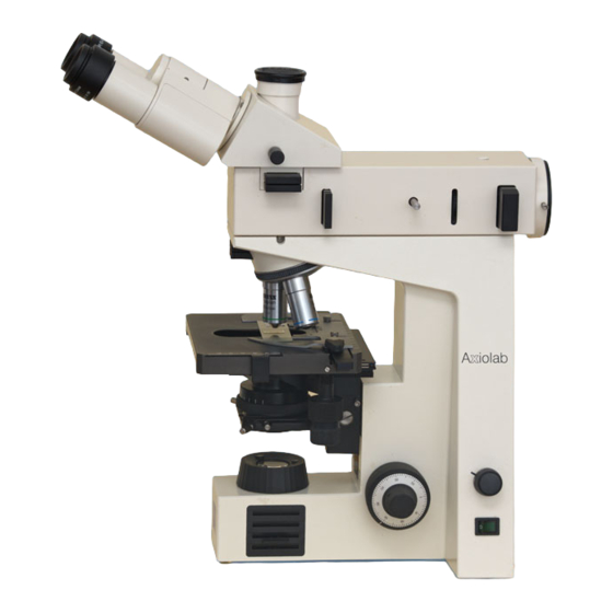
Page 10: Overall View Of The Axiolab A Reflected-Light Microscope
Carl Zeiss Axiolab A Overall View of the Axiolab A Reflected-Light Microscope B 40-015 e 06/99... -
Page 11: Description
Axiolab A Carl Zeiss DESCRIPTION Contents DESCRIPTION .........................1-2 Name; Intended Application,....................1-2 Instrument Description.....................1-2 Microscope Configurations and Modules................1-5 Function Elements (see Fig. 1-5, after this table) ............. 1-12 Objectives........................1-18 Eyepieces........................1-19 Stage Micrometers and Eyepiece Reticles................ 1-20 Technical Data ....................... 1-22... -
Page 12: Name; Intended Application
Axiotron 2 / Axiotron DUV Axioskop 2 FS / Axioskop 2 FS The Axiolab A reflected-light microscope is a light microscope suitable for use in all areas of research and industry involving opaque material, e.g. in metallography (metallic and compound materials) -
Page 13: Fig. 1-1 Axiolab A Main Modules
Both the fixed stage and the glide stage can be locked in a top or a bottom stop. The maximum specimen height is 45 mm. The mechanical stage is a component of the transmitted-light version of the Axiolab A and permits the particularly sensitive moving of transparent objects. For opaque specimens, this mechanical stage can be equipped with a special specimen holder, permitting the maximum specimen height of 18 mm. -
Page 14: Fig. 1-2 Optical Design Of The Axiolab A With Transmitted-Light Equipment
(3200 K) is automatically reached in the end stop. The XBO 75 or HBO 50 illuminators can also be attached to the Axiolab A for examinations requiring a high illuminance. Other features: adjustable aperture diaphragm and homogeneous illumination of object fields of up to dia. -
Page 15: Microscope Configurations And Modules
Axiolab A Carl Zeiss The optical performance of the Axiolab A can be ideally matched to the relevant requirements by using various objectives which are inserted into a 5-position nosepiece (1-1/6). The camera port (1-1/9) attached to the binocular reflected-light tube (1-1/8) is available for the documentation of microscope images. -
Page 16: Fig. 1-3 Axiolab A Microscope Configurations
Carl Zeiss Axiolab A Fig. 1-3 Axiolab A microscope configurations 06/99 B 40-015 e... - Page 17 Cat. No. Fixed Glide Mechani- stage stage cal stage Configurations Microscope Axiolab A with fixed mechanical stage 490960-9804-000 Microscope Axiolab A with glide stage 490962-9804-000 Microscope Axiolab A with mechanical stage and 490961-9804-000 additional transmitted-light equipment Selected modules for configuration 1...
-
Page 18: Fig. 1-4 Axiolab A Accessories
Carl Zeiss Axiolab A Fig. 1-4 Axiolab A accessories (1 of 2) 06/99 B 40-015 e... - Page 19 Axiolab A Carl Zeiss Axiolab A accessories Cat. No. Fixed Glide Mechani- stage stage cal stage STAGES ! ! ! ! Glide stage with stage carrier 453509-0000-000 453517-9901-000 Mechanical stage 75 35 R/A with ceramic surface and short drive, plus: 1.2.1...
- Page 20 Carl Zeiss Axiolab A Fig. 1-4 Axiolab A accessories (2 of 2) 1-10 06/99 B 40-015 e...
- Page 21 Axiolab A Carl Zeiss Axiolab A accessories Cat. No. Fixed Glide Mechani- stage stage cal stage ! ! ! ! ! ! ! ! Retrofit package for transmitted-light illumination (can only be fitted by service personnel), consisting of: 453517-9901-000 - Mechanical stage 75...
-
Page 22: Function Elements (See Fig. 1-5, After This Table)
Dust protection slider These two dust protection sliders should always remain in the (2 pcs.) Axiolab A microscope; technique sliders can also be inserted only if transmitted-light equipment is available Objective nosepiece Carrier for the maximum of 5 objectives which are swung into the... - Page 23 Axiolab A Carl Zeiss Item Designation Purpose/description Fuse holder Holder for two fuse inserts Fuse insert T 0.8 A; 250 V; 5 20 mm Mains cable To apply the supply voltage Pushrod Pushrod to change the beam path between - observation through the binocular tube (pushrod pushed in)
- Page 24 Carl Zeiss Axiolab A Item Designation Purpose/description ”Luminous intensity” control Continuous control of the illuminance of the light source by changing the lamp voltage in the range from > 1.5...6 V. At 6 V (right stop) the 3200 K color temperature for color photography is reached.
- Page 25 Axiolab A Carl Zeiss Stand 6 V, 30 W halogen illuminator Reflected-light illuminator H Camera port Binocular tube Eyepiece, fixed Focusing eyepiece Dust protection slider 5-position objective nosepiece Specimen stage, fixed Coaxial coarse and fine drive (left, also see item 29) Connecting cable for halogen illuminator ”A/D”...
-
Page 26: Fig. 1-5 Axiolab A Function Elements
Carl Zeiss Axiolab A Fig. 1-5 Axiolab A function elements (1 of 2) 1-16 06/99 B 40-015 e... - Page 27 Axiolab A Carl Zeiss Fig. 1-5 Axiolab A function elements (2 of 2) B 40-015 e 06/99 1-17...
-
Page 28: Objectives
Epiplan 10 /0.20 /- where objective magnification, with a defined color ring on the objective being allocated to each magnification step (Carl Zeiss color ring code) 0.20 numerical aperture infinite tube length can be used with cover slip thickness D = 0 or 0.17 mm can only be used without cover slip, that means D = 0 0.17... -
Page 29: Eyepieces
Axiolab A Carl Zeiss The following objectives are available for the Axiolab A: Microscopy Objective Magnification/ Free working Cover slip Cat. No. technique Num. Aperture distance thickness in mm D in mm Reflected-light Epiplan brightfield Epiplan 19.8 442920-0000-000 5 /0.13 Epiplan 18.4... -
Page 30: Stage Micrometers And Eyepiece Reticles
Carl Zeiss Axiolab A Stage Micrometers and Eyepiece Reticles Measuring and counting using the microscope requires stage micrometers and eyepiece reticles, a small selection of which is listed below: Illustration Description, Technical data Cat. No. stage micrometer, positive 5 + 100/100 y 474026-0000- D = 0.17 mm... - Page 31 Axiolab A Carl Zeiss 474068-0000- net micrometer 12.5 12.5 / 5 ; 10, d = 26 mm area 12.5 12.5 mm, divided in fields of 454075-0000- photo reticle MC 2.5 / d = 26 mm for 35 mm photography with an additional magnification of 2.5...
-
Page 32: Technical Data
Carl Zeiss Axiolab A Technical Data Dimensions and weight Dimensions (width depth height) ..............180 430 mm Footprint (recommended with mat)...................440 310 mm Weight..........................approx. 10 kg Ambient conditions for storage and transport (in packaging) Permissible ambient temperature ..................-40 to +50 °C Permissible relative humidity ....................max. - Page 33 Axiolab A Carl Zeiss Mechanical data of specimen stages Stage models................fixed stage/glide stage/mechanical stage Maximum specimen height: stage at bottom stop (not possible for mechanical stage)........... 45 mm stage at top stop ......................20 mm Light source 6 V, 30 W halogen illuminator: halogen lamp with square flat-core filament ..........
- Page 34 Carl Zeiss Axiolab A 1-24 06/99 B 40-015 e...
-
Page 35: Start-Up
Axiolab A Carl Zeiss START-UP Contents Start-Up .........................2-3 Unpacking the Instrument....................2-3 Screw in Objectives......................2-3 Insertion of Eyepieces ......................2-4 2.3.1 Insertion of Eyepiece Reticle .....................2-4 2.3.2 Compensation of Ametropia when Eyepiece Reticles are used ...........2-5 Setting of Interpupillary Distance..................2-5 Attachment of Reflected-Light Halogen Illuminator............2-6 Retrofit the Transmitted-Light Halogen Illumination ............2-6... - Page 36 Carl Zeiss Axiolab A B 40-015 e 06/99...
-
Page 37: Unpacking The Instrument
Axiolab A Carl Zeiss START-UP The three versions of the Axiolab A reflected-light microscope, including accessories, are supplied in standard packaging. We would recommend you to keep the transport cases for storage or return of the instrument to the manufacturer. -
Page 38: Insertion Of Eyepieces
Carl Zeiss Axiolab A Insertion of Eyepieces Remove both protection caps from the binocular tube. Insert the fixed eyepiece, e.g. E-PL 10 /20 Br., in one tube and the focusing eyepiece E-PL 10 /20 Br. foc. in the other tube. -
Page 39: Compensation Of Ametropia When Eyepiece Reticles Are Used
Axiolab A Carl Zeiss 2.3.2 Compensation of Ametropia when Eyepiece Reticles are used The correct use of an eyepiece reticle requires two focusing eyepieces, e.g. PL 10 /20 Br. foc., to enable compensation of ametropia. Use the eyelens of the focusing eyepiece to focus on the line figure of the eyepiece reticle; focus on the edge of the field of view if no eyepiece reticle is used. -
Page 40: Attachment Of Reflected-Light Halogen Illuminator
”Retrofit package for transmitted light” (1-4/7). The transmitted-light illumination equipment can be subsequently mounted to the Axiolab A only by Carl Zeiss service personnel. The transmitted-light illumination package consists of: - mechanical stage 75... -
Page 41: Switch On The Transmitted-Light Halogen Illuminator
To change to transmitted-light operation, press the A/D converter (1-5/13) at the rear of the Axiolab A into the lower position. The functions of the on/off switch (1-5/28) and the "illuminance" control (1-5/27) are retained, regardless of the position of the AD converter A/D (1-5/13) (see section 1.5). -
Page 42: Set The Luminous-Field Diaphragm
Carl Zeiss Axiolab A Set the Luminous-Field Diaphragm The pushrod (2-6/1) for the luminous-field diaphragm has two positions: pushed in: the full field of view is visible without restriction. pulled out: the visible field of view is reduced to approx. 1/3 of the overall diameter. This can be useful as an aid to find the object plane, i.e. -
Page 43: Operation
Axiolab A Carl Zeiss OPERATION Contents Operation ........................3-3 Switch on the Instrument....................3-3 Illumination and Contrasting Techniques ................3-4 3.2.1 Setting of Reflected-Light Brightfield ................3-4 3.2.2 Setting of Reflected-Light Polarization ................3-5 3.2.3 Setting of Transmitted-Light Polarization with extended Polarization Equipment....3-5 3.2.4 Setting of Epi-Fluorescence .................... 3-13 3.2.5... - Page 44 Carl Zeiss Axiolab A B 40-015 e 06/99...
-
Page 45: Switch On The Instrument
Axiolab A Carl Zeiss OPERATION Switch on the Instrument Switch on the instrument via the on/off switch (3-1/6). The green line control lamp in the switch (3- 1/6) must light up. The halogen lamp 6 V, 30 W in the reflected-light illuminator (3-1/2) must light The “I”... -
Page 46: Illumination And Contrasting Techniques
The description of the illumination and contrasting techniques is based on the following microscope settings: The Axiolab A microscope is ready for operation as described in chapter 2 and switched on as described in section 3.1. The pushrod (3-2/3) has been pushed in to direct 100% of the light to the observation port of the binocular tube. -
Page 47: Setting Of Reflected-Light Polarization
Carl Zeiss 3.2.2 Setting Reflected-Light Polarization The Axiolab A microscope is ready for operation as described in chapter 2, and switched on as described in section 3.1. Pull out the plane glass pushrod (3-3/1). Pull out the dust protection sliders (3-3/2+6) from the reflected-light illuminator H. -
Page 48: Fig. 3-4 Centering Of Objectives
Carl Zeiss Axiolab A Centering of Objectives (only for Axiolab Pol catalogue No. 450910-0000-000) Fig. 3-4 Centering of objectives When the Pol stage (3-4/3) and uncentered objectives are turned, object details above the center of the eyepiece cross migrate to circular paths (3-4/1 - dashed line). The following procedure is required to center the objectives: Unlock the stage stop by turning screw (3-4/6) by approx. -
Page 49: Fig. 3-5 Setting Of Transmitted-Light Polarization
Axiolab A Carl Zeiss Transmitted-Light Polarization - Detection of Birefringence This technique is used for the examination of transparent, birefringent objects. Birefringence can be recognized, with crossed polarizer and analyzer, by the otherwise dark field of view being brightened 4 times when the specimen stage is rotated about 360°. -
Page 50: Fig. 3-7 Schematic Diagram Of The Color Chart In Addition And Subtraction Position
Carl Zeiss Axiolab A Transmitted-Light Polarization - Determination of the n Vibration Direction and Determination of the Path Difference -400 Fig. 3-6 Determine the n vibration direction using the example of an artificial fiber Application The position of the two directions with the relatively highest (n... - Page 51 Axiolab A Carl Zeiss Conclusions The n -direction of the -compensator is NE-SW oriented. The environment of the fiber exhibits a dark, first-order red (path difference is one ; approx. 550 nm). The fiber itself appears greenish blue (path difference approx. 700 nm). The higher interference color (700 nm) can only have been created by addition of the path differences of the object (approx.
- Page 52 Carl Zeiss Axiolab A Transmitted-Light Polarization - Determination of the Optical Character of Crystals Application The optical character of transparent and weakly absorbing crystals must be determined for the diagnosis of crystals. The determination is made in conoscopic observation. The main field of application is classical petrography.
-
Page 53: Fig. 3-8 Determine The Optical Character Of Crystals
Axiolab A Carl Zeiss Uniaxial Crystals If the optical axis of a uniaxial crystal is oriented parallel to the observation direction, a dark cross which can be surrounded by concentric interference rings (depending on birefringence and specimen thickness) becomes visible in the conoscopic observation mode. These interference rings are also called isochromats (from the Greek isos = equal and chroma = color). - Page 54 Carl Zeiss Axiolab A Reflected-Light Polarization - Detection of Bireflection and Reflection Pleochroism Application Polished sections of ores, coals, ceramic products, certain metals and metal alloys display a different reflection behavior, depending on the orientation of the crystals or the object details. Therefore, this technique also represents a further contrasting method.
-
Page 55: Setting Of Epi-Fluorescence
The examined material can be autofluorescent or may have been mixed with fluorescent substances (fluorochromes). The epi-fluorescence technique can be performed using equipment for simple fluorescence examinations with the Axiolab A, together with the 6 V, 30 W halogen illuminator (3-9/1) and the standard brightfield beam splitter. The equipment consists of:... -
Page 56: Setting Of Transmitted-Light Brightfield (Köhler Illumination)
(3-10/4), which should be open by approx. 2/3 of its size (marking on condenser positioned to 0.5). For further information on the use of the Axiolab A for transmitted-light examinations and the relevant accessories please see the manual Fig. 3-10 Setting of transmitted-light... -
Page 57: Attachment Of Microscope Stages And Specimen Holders
Axiolab A Carl Zeiss Attachment of Microscope Stages and Specimen Holders The Axiolab A microscope is available with three different stages: - fixed stage (3-11/1), - gliding stage (3-11/2) or - mechanical stage (3-11/3). The retaining clips (3-11/4) are used to hold... -
Page 58: Attachment Of Pol Rotary Stage
Carl Zeiss Axiolab A 3.3.1 Attachment of Pol Rotary Stage Fig. 3-13 Pol rotary stage- setting of specimen mount and stop The stage clips (3-13/3) are used to mount the specimen on the Pol rotary stage (3-13/8). They are inserted into two of the three drilled holes (3-13/9) and, depending on the size of the specimen carrier or the search area, used diagonally, opposite to each other or parallel. -
Page 59: Use Of Polished Section Attachment
Axiolab A Carl Zeiss Use of Polished Section Attachment The polished section attachment from the line of accessories provides another possibility of holding objects for examinations in incident light. It has been intended for use with the gliding stage. Basically, the polished section attachment can also be used with the fixed stage. Use a screwdriver to remove the two bolts (3-14/5) on the underside and place the attachment on the fixed stage without any securing elements. -
Page 60: Photomicrography And Videomicroscopy
100% changeover, simultaneous observation and photography is not possible. Special adapters allow commercially available 35 mm cameras or microscope cameras (e.g. MC 80 ) to be attached to the camera port of the Axiolab A. For the use of photomicrography equipment please see the relevant manuals. Fig. 3-15... -
Page 61: Attachment Of Photomicrography Equipment
Axiolab A Carl Zeiss 3.5.1 Attachment of Photomicrography Equipment Attachment of SLR Camera, e.g. CONTAX 167 MT Screw T2 adapter for the CONTAX bayonet (3- 16/3) on the 2.5 connector for T2 (3-16/4) (456005-0000-000). Attach the camera housing (3-16/2) and the cable release (3-16/1), if required. - Page 62 T2 adapter for NIKON (F bayonet) 416009-0000-000 T2 adapter for PENTAX (KA bayonet) 416011-0000-000 For detailed information on SLR cameras please see operating manual from Carl Zeiss B 40- 046 e entitled "Photomicrography with 35 mm SLR Cameras". 3-20 B 40-015 e 06/99...
-
Page 63: Fig. 3-17 Attachment Of Mc 80 Dx
For daylight color reversal film, the CB 12 conversion filter must also be used. detailed information MC 80 please operating manual from Carl Zeiss B 40-036 e, "MC 80 Microscope Camera". Fig. 3-17 Attachment of MC 80 B 40-015 e 06/99 3-21... -
Page 64: Attachment Of Adapters For Video Cameras
3.5.2 Attachment of Adapters for Video Cameras The following video adapters with 60 mm interface permit the attachment of one-chip b/w and color CCD cameras and 3-chip color CCD cameras to the camera port of the Axiolab A Tube Adapter... - Page 65 Carl Zeiss Attachment of video cameras: Loosen three hexagonal screws and remove dust cover from the Axiolab A camera tube. Screw video adapter or video zoom adapter with C-mount thread into the video camera. Insert video adapter or video zoom adapter in ENG 2/3“ or ENG ½“ bayonet of the video camera and clamp it tight.
-
Page 66: Insertion Of 8 Drawing Eyepiece
The 8 drawing eyepiece (444126-0000-000) is an accessory for microscopic drawing and can only be used in combination with the binocular reflected-light tube 30°/20 H on the Axiolab A. It contains a beam splitter which allows the simultaneous observation of the microscope image and the drawing area. -
Page 67: Care, Troubleshooting And Service
Axiolab A Carl Zeiss CARE, TROUBLESHOOTING AND SERVICE Contents CARE, TROUBLESHOOTING AND SERVICE..............4-3 Maintenance of the Instrument ..................4-3 Troubleshooting ......................4-4 Requesting Service......................4-6 B 40-015 e 06/99... - Page 68 Carl Zeiss Axiolab A B 40-015 e 06/99...
-
Page 69: Maintenance Of The Instrument
When using the Axiolab A in humid climatic zones, proceed as follows: Store the Axiolab A in bright, dry and well ventilated rooms with a humidity of less than 85%; store particularly sensitive components and accessories, such as objectives and eyepieces, in a dry closet. -
Page 70: Troubleshooting
Carl Zeiss Axiolab A Troubleshooting Troubleshooting on the Axiolab A microscope is limited to only a few actions: Checking the line cable Checking the set instrument voltage and changing the fuses Checking the illumination and changing the lamp Defective fuse(s) - Page 71 Axiolab A Carl Zeiss Changing the 6 V, 30 W Reflected-Light Halogen Lamp The following procedure is required to change the lamp of the 6 V, 30 W reflected-light halogen illuminator: Switch off the lamp supply; if required, allow the illuminator to cool down for approx. 15 minutes.
-
Page 72: Requesting Service
Requesting Service All repairs of mechanical, optical or electronic components inside the instrument and of the electrical components of the Axiolab A may only be performed by Carl Zeiss service staff or specially authorized personnel. To ensure the optimum setting and trouble-free function of your microscope even for a longer period of time, we would recommend you to conclude a service/maintenance contract with Carl Zeiss. -
Page 73: Annex
Axiolab A Carl Zeiss Annex List of Abbreviation ........................A-3 Certification in Accordance with DIN EN ISO 9001 / DIN EN 46001..........A-5 EC Conformity Declaration ......................A-7 B 40-015 e 06/99... - Page 74 Carl Zeiss Axiolab A B 40-015 e 06/99...
- Page 75 Axiolab A Carl Zeiss List of Abbreviations incident light, analyzer Alternating Current eyepieces suitable for spectacle wearers Charge-Coupled Device Canadian Standards Association transmitted light, filter attenuation in % German Standards Association Dmr, d diameter coding system for electronic data, e.g. film speed...
- Page 76 Carl Zeiss Axiolab A slow-blow fuse type television T2-Adapter standard adapter for 35 mm cameras B 40-015 e 06/99...