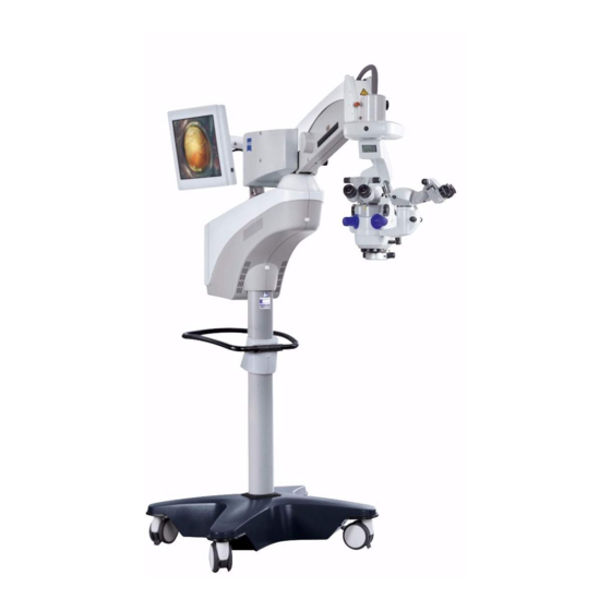
Zeiss opmi lumera 700 User Manual
On floor stand
Hide thumbs
Also See for opmi lumera 700:
- User manual (150 pages) ,
- Instructions for use manual (236 pages) ,
- Basic instructions (2 pages)

Related Manuals for Zeiss opmi lumera 700


Summary of Contents for Zeiss opmi lumera 700
- Page 1 Carl Zeiss lmjf=irjbo^ =TMM ® çå=cäççê=pí~åÇ User Manual G-30-1673-en Version 3.0 2010-07-01...
-
Page 2: Opmi Lumera
– A list of abbreviations, key words and technical terms in the annex facili- tates the search for specific terms. Applicable area This user manual applies to OPMI LUMERA 700 with the following identification: – Rating label number: 305953-9900-000 –... -
Page 3: Table Of Contents
OPMI LUMERA® 700 Chapter Overview Chapter: Safety measures Chapter: System overview Chapter: Preparations for use Chapter: Operation Chapter: What to do in the event of malfunctions Chapter: Care and maintenance Chapter: System data Chapter: Annex / Options) Chapter: Indexes Version 3.0 G-30-1673-en Page 3... - Page 4 OPMI LUMERA® 700 Version 3.0 Page 4 G-30-1673-en...
- Page 5 OPMI LUMERA® 700 Safety measures Safety measures Key to symbols .................. 7 Hazard symbols ...................7 Information symbols..................7 Target group ..................8 Field of use ..................9 Intended use ....................9 Normal use....................9 Notes for the operator..............10 Requirements for operation............. 13 Prior to the very first use................13 Before every use ..................13 During use....................15...
- Page 6 Safety measures OPMI LUMERA® 700 Labels on the suspension system............... 32 Version 3.0 Page 6 G-30-1673-en...
-
Page 7: Key To Symbols
OPMI LUMERA® 700 Safety measures Key to symbols We would like to inform you about safety aspects which must be observed when handling this device. This chapter contains a summary of the most im- portant information concerning matters relevant to instrument safety. Hazard symbols The following safety information has been incorporated into the user manual. -
Page 8: Target Group
Installation and service work not described in this manual must only be per- formed by specialists from Carl Zeiss. Version 3.0 Page 8 G-30-1673-en... -
Page 9: Field Of Use
Safety measures Field of use Intended use OPMI LUMERA 700 is a surgical microscope intended for the illumination and magnification of the surgical area and for the support of visualization in sur- gical procedures in the field of ophthalmology. Normal use In line with the intended use of the system, you can use it for surgical proce- dures on both the anterior segment of the eye (e.g. -
Page 10: Notes For The Operator
• Modifications and repairs of this device or any equipment operated to- gether with this device may only be performed by the Carl Zeiss service team or other persons authorized by CZS. • Connect the system to a special emergency backup power supply in ac- cordance with the regulations and directives applicable in the country of use. - Page 11 • Should the device be transported over longer distances (e.g., moving, re- turn for repairs etc.), only use the original packaging or special return packages. Please contact your dealer or the Carl Zeiss Service department. • Always turn off the device before connecting to or removing from the power supply, if the device is not being used for a long time or if the de- vice is being cleaned.
- Page 12 Safety measures OPMI LUMERA® 700 • Condensation of humid air may occur if you move the system from a cold place (<10°C) to a warm place. Before switching on the system, allow it to adapt to room temperature for at least 1 hour. Version 3.0 Page 12 G-30-1673-en...
-
Page 13: Requirements For Operation
Safety measures Requirements for operation Prior to the very first use Carl Zeiss Service or an expert authorized by CZS will install the system. Please make sure that the following requirements continue to be met for further op- eration: The connecting components have been properly connected. The screw connections have been firmly tightened. - Page 14 • Never attempt to forcefully connect any electrical connectors (plugs, sock- ets). If connection is not readily possible, check whether the plug fits the socket. If any of the connectors are damaged, have Carl Zeiss Service re- pair them. • In order to avoid the device from rolling off inadvertently, use the locking mechanism on the base of the suspension system and secure the device.
-
Page 15: During Use
• In order to prevent phototoxic damages to the patient's eye, adjust the ir- radiation intensity and the associated irradiation time by selecting the ap- propriate illumination setting. The values recommended by Carl Zeiss can be found in table "Maximum radiation exposure times" on page 22. Any deviation from these values is only permissible when medically justified. -
Page 16: After Every Use
Safety measures OPMI LUMERA® 700 • If a failure occurs which you cannot correct with the aid of the chapter "What to do in the event of malfunctions“, attach a sign to the device stat- ing it is out of order and contact our service representative. •... -
Page 17: Liability And Warranty
OPMI LUMERA® 700 Safety measures Liability and warranty Warranty and liability depend on the applicable contractual stipulations. NOTE Loss of warranty Modifications to this system are not permissible. The manufacturer is not li- able for damage caused by unauthorized persons tampering with the system. Furthermore, this will forfeit any rights to claim under warranty. -
Page 18: Measures To Prevent Phototoxic Injury
Exposure time to light In the following, comments on these aspects are given and a description of how Carl Zeiss, as a manufacturer, makes allowance for them in its systems. Illumination characteristics (spectral composition) Studies on the exposure of the eye to light of varying spectral composition date back to the early 1950s. -
Page 19: Angle Of Illumination
OPMI LUMERA® 700 Safety measures surgery. For this reason, the brightness of the light source in Carl Zeiss systems is con- Brightness control tinuously variable. This permits the surgeon to optimally adapt the light inten- sity at the patient's eye to the conditions existing in each case. -
Page 20: Exposure Time To Light
This problem has been solved by Carl Zeiss by the use of a retina protection device that can be swung into the microscope's illumination beam path and a swing-in retina protection filter (blue barrier filter). - Page 21 The illumination of the peripheral area generates a much higher im- pact on the retina; however, that does not apply to the macula (depending on the position of the eye). When performing a cataract surgery Zeiss recom- mends dimming the surrounding area somewhat darker than the central spot of the red reflex.
- Page 22 Safety measures OPMI LUMERA® 700 The calculations are based on limits recommended by the industrial safety board and refers to daily stresses per . When determining the limits, a safety factor of 10 was applied. The use of a blue barrier filter increases the recommended exposure time by a factor of 5 for xenon and 3 for halogen compared with the values specified below.
- Page 23 OPMI LUMERA® 700 Safety measures H. Stiller, and B. Rassow, "Light hazards to the patient's retina from oph- List of references thalmic instruments," Applied Optics-OT 30, 2187-2196 (1991). American Conference of Governmental Industrial Hygienists, "Documenta- tion of the Threshold Limit Values for physical agents. 7th Edition," (American Conference of Governmental Industrial Hygienists, Cincinnati, 2001).
-
Page 24: Safety Devices
Safety measures OPMI LUMERA® 700 Safety devices 1 Release bar for magnetic brake Enables the person who is unsterile to activate the magnetic brake of the suspension system. 2 Adjustment screw for limiting downward movement Is used to set the minimum working distance of the surgical microscope to the operating area in the vertical direction. - Page 25 OPMI LUMERA® 700 Safety measures Fig. 1: Safety devices Version 3.0 G-30-1673-en Page 25...
- Page 26 Safety measures OPMI LUMERA® 700 9 Switch for manual operation In the event that one of the major functions fails (XY movement, focus, zoom, light control), leading to the impairment of further functions, you can press this switch to change to the manual mode. The system reacts as follows: –...
- Page 27 OPMI LUMERA® 700 Safety measures Fig. 2: Switch for manual operation Version 3.0 G-30-1673-en Page 27...
- Page 28 Safety measures OPMI LUMERA® 700 10 Cover indicating the operating status of the halogen lamp – If the cover is closed, the main lamp is on. – If the cover is open (yellow marking on the side), the main lamp has failed and the backup lamp is on.
- Page 29 OPMI LUMERA® 700 Safety measures Fig. 4: Superlux Eye lamp housing Fig. 5: Halogen lamp housing with Superlux Eye Version 3.0 G-30-1673-en Page 29...
-
Page 30: Symbols And Labels On The Device
Safety measures OPMI LUMERA® 700 Symbols and labels on the device CAUTION Risk of injury! Observe all warnings and information labels! • When discovering that one of the following labels is missing on the equipment or a label has become illegible, please contact us or one of our authorized dealers. - Page 31 OPMI LUMERA® 700 Safety measures Fig. 6: Labels on the microscope Version 3.0 G-30-1673-en Page 31...
- Page 32 Safety measures OPMI LUMERA® 700 Labels on the suspension system 1 Friction information Explanation of brake effect, which can be achieved by actuating the fric- tion adjustment knob. 2 Warning label "Maximum load capacity" The maximum weight of the add-ons (accessory equipment) to the micro- scope must not exceed 9 kg! 3 Information label "Follow instructions"...
- Page 33 OPMI LUMERA® 700 Safety measures Fig. 7: Labels on the suspen- sion system Version 3.0 G-30-1673-en Page 33...
- Page 34 – SIP number A unique identification number assigned to your system. A product file is maintained by Carl Zeiss for this SIP number. 11 Please follow disposal regulations Do not dispose of electrical and electronic waste with domestic waste. Ad- ditional information pertaining to the disposal of electrical and electronic waste can be found in Chapter "Maintenance and care"...
- Page 35 OPMI LUMERA® 700 Safety measures Fig. 8: Labels on the suspen- sion system 14 "FCP Gateway WL" label (optional) This device complies with Part 15 of the FCC Rules and with RSS 210 standard (Canada). Operation is subject to the following conditions: –...
- Page 36 Safety measures OPMI LUMERA® 700 17 "Maximum load on instrument tray" warning label Indicates that the maximum load capacity of the instrument tray for acces- sory equipment is 13 kg. 18 Information label "Follow instructions" Follow instructions or referenced documents. 19 USB port Identifies the connector e.g.
- Page 37 OPMI LUMERA® 700 Safety measures Fig. 9: Labels on the suspen- sion system Version 3.0 G-30-1673-en Page 37...
- Page 38 The Superlux Eye light source contains an integrated Xenon light. To re- place a Xenon lamp, only use lamps designed for ophthalmic surgery and specially approved by Carl Zeiss. 35 Changing the lamps The label shows the three steps for the replacement of a lamp.
- Page 39 OPMI LUMERA® 700 Safety measures Fig. 10: Labels on halogen lamp housing Fig. 11: Labels on Superlux Eye lamp housing Fig. 12: Labels on halogen and Superlux Eye lamp housing Version 3.0 G-30-1673-en Page 39...
- Page 40 Safety measures OPMI LUMERA® 700 Version 3.0 Page 40 G-30-1673-en...
-
Page 41: System Overview
OPMI LUMERA® 700 System overview System overview System overview................42 Components of the surgical microscope .......... 44 Controls of the main microscope and assistant's microscope .....52 Controls for the tubes................54 Controls for the widefield eyepieces ............55 Components of the XY coupling ............56 Controls of the XY coupling...............56 Components of the floor stand............ - Page 42 Slit illuminator (integrated) – Keratoscope (integrated) – 3CCD SD or HD video camera (integrated) – Integrated video recording function via USB port – RESIGHT 500 / 700 (fundus viewing systems) – Instrument tray (7) for Zeiss equipment Version 3.0 Page 42 G-30-1673-en...
- Page 43 OPMI LUMERA® 700 System overview – 17" video monitor (8) Fig. 13: System overview Version 3.0 G-30-1673-en Page 43...
-
Page 44: Components Of The Surgical Microscope
System overview OPMI LUMERA® 700 Components of the surgical microscope 1 Tubes for the main microscope and for the assistant's microscope The following tubes can be installed: – Invertertube - manually adjustable (optional) The tube may be tilted by 110°. It is particularly suitable in connection with the fundus imaging system, as it is possible to upright an inverted image. - Page 45 OPMI LUMERA® 700 System overview Fig. 14: Components of the surgical microscope Version 3.0 G-30-1673-en Page 45...
- Page 46 System overview OPMI LUMERA® 700 3 Integrated slit illuminator (option) The slit illuminator is an additional illumination system for OPMI LUMERA 700. It provides a bright, sharply delimited slit image for high-contrast ob- servation of the anterior and posterior segments of the eye. The slit position (right, left) and the size of the slit apertures (slit width of 0.2 mm, 2 mm, 3 mm and 4 mm) are set via the 5.7"...
- Page 47 OPMI LUMERA® 700 System overview Fig. 15: Components of the surgical microscope Version 3.0 G-30-1673-en Page 47...
- Page 48 10 Connector for Invertertube E This connector permits you to control the motorized image inversion of In- vertertube E via OPMI LUMERA 700. If RESIGHT 700 is also connected, the two devices can be synchronized so that the field of view is always dis- played in the correct orientation.
- Page 49 OPMI LUMERA® 700 System overview Fig. 16: Components of the surgical microscope Version 3.0 G-30-1673-en Page 49...
- Page 50 11 Assistant's microscope The integrated assistant's microscope in its standard version comes as an integral part of OPMI LUMERA 700. The assistant sees the same image as the main surgeon in the same image quality and without any loss of light.
- Page 51 OPMI LUMERA® 700 System overview Fig. 17: Components of the surgical microscope Version 3.0 G-30-1673-en Page 51...
-
Page 52: Controls Of The Main Microscope And Assistant's Microscope
System overview OPMI LUMERA® 700 Controls of the main microscope and assistant's microscope 1 Clamping screw of the assistant's tube Locks the assistant's tube in place after it has been adjusted within its 12° rotational range 2 Rotary knob for zoom drive of assistant's microscope As an option, the assistant's microscope can also be fitted with a manually adjustable 5x magnification changer. - Page 53 OPMI LUMERA® 700 System overview Fig. 18: Controls of the main microscope and assistant's microscope Version 3.0 G-30-1673-en Page 53...
-
Page 54: Controls For The Tubes
System overview OPMI LUMERA® 700 Controls for the tubes 180° tiltable tube and inclined tube 1 Eyepiece mount 2 Pupillary distance (PD) adjustment knob The correct position has been reached when the two eyepiece images merge into one. You can read off the PD setting on the adjustment knob. Inverter tube and inverter tube E 3 Eyepiece mount 4 Knob for eye distance (interpupillary distance) -
Page 55: Controls For The Widefield Eyepieces
OPMI LUMERA® 700 System overview Controls for the widefield eyepieces NOTE Widefield eyepieces with magnetic coupling Please note that the usual rules for the handling of magnets must be ob- served for eyepieces removed from the tube: • Do not place the eyepiece near instruments which may be magnetizable. •... -
Page 56: Components Of The Xy Coupling
System overview OPMI LUMERA® 700 Components of the XY coupling Controls of the XY coupling CAUTION Risk of injury! When pressing the XY reset button, the device may be put in focus and can be lowered. • Ensure the working distance between microscope and the patient is al- ways larger than the moving range of the microscope. - Page 57 OPMI LUMERA® 700 System overview Fig. 21: Controls of the XY coupling Version 3.0 G-30-1673-en Page 57...
-
Page 58: Components Of The Floor Stand
The downward movement of the suspension arm can be limited as required. 2 Instrument tray (optional) The Instrument tray is designed for the installation of Zeiss equipment MediaLink 100, VISULAS 532s or the MediLive Trio series. CAUTION... - Page 59 OPMI LUMERA® 700 System overview Fig. 22: Components of the floor stand Version 3.0 G-30-1673-en Page 59...
- Page 60 System overview OPMI LUMERA® 700 4 Lamp housing The light source in the lamp housing provides the SCI of the surgical mi- croscope. The device can be fitted with a halogen, Superlux Eye or a com- bination of both light sources Superlux Eye (standard fea- The lamp housing with Superlux Eye light source is an integrated standard ture)
- Page 61 OPMI LUMERA® 700 System overview This lamp housing comprises the two light sources described above. The Halogen/Superlux Eye (option) light sources are factory-configured according to your order and can be used as follows: – One of the two light sources is used as the main light source of the surgical microscope.
- Page 62 • Adjust the intensity of the irradiation and the resulting irradiation time by selecting the appropriate illumination setting. The values recommended by Carl Zeiss can be found in table "Maximum radiation exposure times" in Chapter "Safety measures". 6 Stand column A handle is attached to the column, thus making it easy to move the unit around.
- Page 63 OPMI LUMERA® 700 System overview Fig. 24: Components of the floor stand 10 9 Version 3.0 G-30-1673-en Page 63...
-
Page 64: Controls Of The Lamp Housing
System overview OPMI LUMERA® 700 Controls of the lamp housing CAUTION Lamp failure! – The service life of the xenon lamp is limited to 500 hours. If the service life of the lamp is exceeded, the xenon lamp may suddenly fail. –... - Page 65 OPMI LUMERA® 700 System overview Fig. 25: Halogen lamp housing Fig. 26: Superlux Eye lamp housing Fig. 27: Superlux Eye and hal- ogen lamp housing Version 3.0 G-30-1673-en Page 65...
-
Page 66: Controls On The Suspension Arm
System overview OPMI LUMERA® 700 Controls on the suspension arm 1 Rotary knob for limiting downward travel Is used to set the minimum working distance of the operating area in the vertical direction. (see page 100) 2 Locking the suspension arm Is used during the installation and removal of accessories from the micro- scope. -
Page 67: Controls On The Control And Display Panel
OPMI LUMERA® 700 System overview Controls on the control and display panel 1 5.7" control panel with touchscreen functionality The 5.7" control panel is the central communication interface of the system. It enables the user to access the settings of the microscope, sus- pension system, illumination system, camera (if applicable) and the pro- grammable components of the handgrips and foot control panel. -
Page 68: Connector Panel On The Floor Stand
Cat-5e EIA/TIA-568A-5, i.e. the more recent Class D values from ISO/IEC 11801:2002 or EN 50173-I:2002. 6 RJ45 Ethernet connector (option) For networking OPMI LUMERA 700 and the CALLISTO eye OR manage- ment system. 7 Sliding switch for rated voltage The voltage shown here must correspond to the rated line voltage pro- vided on the site of installation. - Page 69 OPMI LUMERA® 700 System overview Fig. 30: Connectors on the floor stand Version 3.0 G-30-1673-en Page 69...
- Page 70 • Never contact video interfaces while touching the patient. 11 Video output port: Composite (VBS) Analog connection for video components, e.g. recorder, projector or Zeiss accessories such as MediLive Mindstream. Here, the video signal is transmitted according to the Composite VBS standard (shared line for brightness and color signal).
- Page 71 OPMI LUMERA® 700 System overview Fig. 31: Video ports with in- stalled 3CCD SD camera Version 3.0 G-30-1673-en Page 71...
- Page 72 • Never contact video interfaces while touching the patient. 14 Video output port: Composite (VBS) Analog connection for video components, e.g. recorder, projector or Zeiss accessories such as MediLive Mindstream. Here, the video signal is transmitted according to the Composite VBS standard (shared line for brightness and color signal).
- Page 73 OPMI LUMERA® 700 System overview Fig. 32: Video ports with in- stalled HD camera 15 16 17 18 Version 3.0 G-30-1673-en Page 73...
-
Page 74: Connector Panel For 17" Video Monitor
System overview OPMI LUMERA® 700 Connector panel for 17" video monitor 1 Auto adjust button The auto adjust function allows for the automatic image adjustment of the video monitor in order to obtain a sharp and perfectly positioned pic- ture. The automatic calibration is to be set during initial start-up of the video monitor or when changing the system settings. - Page 75 OPMI LUMERA® 700 System overview Fig. 33: Connections of the 17“ video monitor Version 3.0 G-30-1673-en Page 75...
-
Page 76: Components Of The Foot Control Panel
System overview OPMI LUMERA® 700 Components of the foot control panel The foot control panel permits you to control various functions of OPMI LUMERA 700. The assignment of the functions to the buttons on the foot control panel is shown on the following page. You can only activate functions that are implemented in the respective system configuration (suspension system, surgical microscope). - Page 77 Rocker switches The default settings (focus/zoom) of the rocker switches are preconfigured horizontally or vertically for each country. However, a Carl Zeiss service tech- nician can change the settings at any time. User-specific changes to these set- tings (see page 142) can be made by yourself at any time.
- Page 78 System overview OPMI LUMERA® 700 Version 3.0 Page 78 G-30-1673-en...
-
Page 79: Preparations For Use
OPMI LUMERA® 700 Preparations for use Preparations for use Configuring the surgical microscope..........80 Replacing components and accessories .............80 Connecting Invertertube E and RESIGHT 700 (option) to the main microscope ................84 Connecting Invertertube E to the assistant's microscope (option)....84 Connecting the second light guide to the accessories ........86 Balancing the system .................87 Connecting the system and accessories ........... -
Page 80: Configuring The Surgical Microscope
Preparations for use OPMI LUMERA® 700 Configuring the surgical microscope Replacing components and accessories CAUTION Risk of injury! The suspension arm may move downward when accessories are changed. • Never exceed the maximum permissible weight capacity of the suspen- sion arm (see page 225). •... - Page 81 OPMI LUMERA® 700 Preparations for use Fig. 34: Changing components Version 3.0 G-30-1673-en Page 81...
- Page 82 Preparations for use OPMI LUMERA® 700 If you use two Invertertubes E (4 and 14) simultaneously, the two tubes may collide with each other when the assistant's microscope is moved from left to right. To avoid this, we recommend mounting an 11 mm intermediate piece (3) between the surgical microscope and tube (4).
- Page 83 OPMI LUMERA® 700 Preparations for use Fig. 35: Changing components Version 3.0 G-30-1673-en Page 83...
-
Page 84: Connecting Invertertube E And Resight 700 (Option) To The Main Microscope
Preparations for use OPMI LUMERA® 700 Connecting Invertertube E and RESIGHT 700 (option) to the main microscope • Plug the connecting cable of Invertertube E into the Invertertube E con- nector (2) of the surgical microscope. The motorized image inversion function of Invertertube E can now be controlled via the system. - Page 85 OPMI LUMERA® 700 Preparations for use The connecting cable of the tube runs straight upward to the suspen- sion system and does not touch the sterile caps on the control knobs of the surgical microscope. Fig. 36: Fixing the connecting cable with a cable clip Version 3.0 G-30-1673-en...
-
Page 86: Connecting The Second Light Guide To The Accessories
Preparations for use OPMI LUMERA® 700 Connecting the second light guide to the accessories CAUTION Risk of injury! A second light guide, which freely hangs from the surgical microscope, may cause retinal damage or slight burns to the patient. • Always turn off the light source for the light guide that is not in use. •... -
Page 87: Balancing The System
OPMI LUMERA® 700 Preparations for use Balancing the system Rebalance the system after every change of accessories. Do not perform the balancing procedure until all accessories have been mounted and there is no patient under the surgical microscope! CAUTION Risk of crushing! Risk of crushing hands or fingers between suspension arm and XY coupling. -
Page 88: Connecting The System And Accessories
Preparations for use OPMI LUMERA® 700 Connecting the system and accessories Connecting the system to the power supply NOTE Risk of tripping! Inappropriate routing of cables increases the risk of tripping. • Always run cables in a manner that will not impede the user's move- ments. - Page 89 OPMI LUMERA® 700 Preparations for use Fig. 39: Connecting the system Version 3.0 G-30-1673-en Page 89...
-
Page 90: Pairing With The Wireless Foot Control Panel (Fcp-Wl)
Preparations for use OPMI LUMERA® 700 Pairing with the wireless foot control panel (FCP-WL) Pairing means the fixed relative assignment of the suspension system and foot control panel. It is required for wireless operation. On first-time pairing, it may take up to 20 s until the radio link between the suspension system and the foot control panel has been established. - Page 91 OPMI LUMERA® 700 Preparations for use Fig. 40: Connecting the wired foot control panel Version 3.0 G-30-1673-en Page 91...
-
Page 92: Connecting The Strain Relief Device
Preparations for use OPMI LUMERA® 700 Connecting the strain relief device Use the strain relief device (1) to prevent that the connected cables are inad- vertently pulled out. Make sure that the remaining cable length between the strain relief device (7) and the connector (8) is approx. 320 mm. Secure the cable in the strain relief device as follows: •... - Page 93 OPMI LUMERA® 700 Preparations for use Fig. 41: Connecting the strain relief device 320 mm Version 3.0 G-30-1673-en Page 93...
-
Page 94: Connecting External Video Devices To An Sd Video Camera (Option)
Connecting the SD video monitor (integrated video recording function via USB port) • Connect the analog video output port (Y/C) on the OPMI LUMERA 700 to the video input port (e.g. Y/C) of your SD video monitor using the follow- ing video cable: –... - Page 95 OPMI LUMERA® 700 Preparations for use Fig. 42: External video devices on integrated SD camera Video in/out MEDIALINK 100 SD signal SD signal SD signal endoscope SD video monitor camera with MEDIALINK 100 SD video monitor with MEDIALINK 100 SD video monitor with integrated video recording function via USB port...
-
Page 96: Connecting External Video Devices To An Hd Video Camera (Option)
– 5 m DVI system cable Connecting the SD video monitor (incl. MEDIALINK 100) • Connect the analog video output port (Y/C) on the OPMI LUMERA 700 to the video input port (e.g. Y/C) of your MEDIALINK 100 using the following video cable: –... - Page 97 OPMI LUMERA® 700 Preparations for use Fig. 43: External video devices on integrated HD camera DVI-D MEDIALINK 100 SD signal HD signal SD signal SD video monitor SD video monitor with MEDIALINK 100 with MEDIALINK 100 HD video monitor without MEDIALINK 100 Version 3.0 G-30-1673-en Page 97...
-
Page 98: Positioning And Aligning The System
Preparations for use OPMI LUMERA® 700 Positioning and aligning the system Relocating the system CAUTION Risk of tipping! Be careful when moving the device across sills; it may easily tip and/or injure a person next to it. • When lifting or pulling the system across a doorsill request the help of a second person. -
Page 99: Positioning The System In The Or
OPMI LUMERA® 700 Preparations for use Positioning the system in the OR Proceed as follows to position the system: • Unlock all locking tabs. • Hold the system by maneuvering handle (1) and carefully push it into a convenient position, e.g. as shown in the illustration below. –... -
Page 100: Adjusting The Limit Of Downward Travel
Preparations for use OPMI LUMERA® 700 Adjusting the limit of downward travel CAUTION Risk of injury! An improperly balanced systems will move upward or downward. • Limit the stroke of the suspension arm to prevent any contact with the patient if the surgical microscope is lowered accidentally. When setting the stroke limits, proceed as follows: •... -
Page 101: Positioning The Assistant's Microscope
OPMI LUMERA® 700 Preparations for use Positioning the assistant's microscope Position the assistant's microscope as follows: • Press the locking button (1) until you have moved beyond the locking point. The locking button is always located on the side opposite the assistant's microscope. -
Page 102: Adjusting The Surgical Microscope
Preparations for use OPMI LUMERA® 700 Adjusting the surgical microscope – The distance between objective lens and working range depends on the focal distance of the selected objective lens. – The best image across all selectable zoom ranges is only possible if the working distance is selected properly. - Page 103 OPMI LUMERA® 700 Preparations for use – Emmetropes: Setting the eyepieces • Set diopter setting ring (5) to 0 diopters (D). – Eyeglass wearers who perform surgery wearing their eyeglasses: • Set diopter setting ring (5) to 0 D. – Eyeglass wearers who perform surgery without their eyeglasses (known prescription): •...
-
Page 104: Setting The Tilt Position
Preparations for use OPMI LUMERA® 700 Setting the tilt position CAUTION Risk of injury! The assistant's microscope is not locked in place, it may swing out if the sur- gical microscope is tipped in the horizontal viewing direction. • Ensure to adjust and lock the assistant's microscope before starting the surgery. -
Page 105: Aligning The Video Monitor (Option)
214). If the video monitor continues to move downward, the gas spring is defective! • Please contact the Carl Zeiss service department. How to align the video monitor: • Pivot the carrier arm (1) and the suspension arm (2) in the desired horizon- tal position. -
Page 106: How To Prepare The Device For Sterile Operation
Attaching asepsis caps For sterile use, the system can be equipped with resterilizable products. The asepsis sets available from Carl Zeiss contain caps and handgrips which can be sterilized in autoclaves. For detailed information on sterilization please see the enclosed instructions "Preparation of resterilizable products" for the respec- tive asepsis sets. -
Page 107: Attaching The Drapes
OPMI LUMERA® 700 Preparations for use Attaching the drapes Sterile single-use drapes are available to cover the system. When draping the system, make sure there is enough slack in the drapes to allow for movement of the microscope carrier and surgical microscope. NOTE Reduced image quality! ®... - Page 108 Preparations for use OPMI LUMERA® 700 Version 3.0 Page 108 G-30-1673-en...
-
Page 109: Operation
OPMI LUMERA® 700 Operation Operation Powering the system up and down ..........111 Function test before use ..............112 Menu structure ................116 Controls on the 5.7" control panel with touchscreen functionality ...118 Symbols and abbreviations on the 5.7" control panel ......119 System-specific configuration ............ - Page 110 Operation OPMI LUMERA® 700 Configuring the video function ............... 159 Daily usage ..................161 Setting the user profile................161 Zooming in and out ................163 How to set the SCI mode and the (optional) keratoscope......164 Setting the XY and focus positions............169 Setting the surgery mode (image inversion and video format) ....
-
Page 111: Powering The System Up And Down
After power-up, the system performs a self-test. During this time (ap- prox. 120 seconds) the Zeiss logo is displayed on the 5.7" control pan- When the surgical microscope is switched on for the first time, the system dis- plays the "Default User"... -
Page 112: Function Test Before Use
Software malfunctions! Malfunctions of the software may impair your work. • In the event of software malfunctions, switch to the manual mode and contact Carl Zeiss Service. Checking the function of the surgical microscope • Check the zoom The buttons of the foot control panel have been configured (see page 142). - Page 113 OPMI LUMERA® 700 Operation • Check the eyepieces / binocular tube / objective lens The surgical microscope and the tube are in a position convenient for you (see page 99). The interpupillary distance has been correctly set (see page 102). The eyecups have been adjusted in such a way that you can see the full field of view (see page 102).
- Page 114 • The use of the RESIGHT 500 / RESIGHT 700 fundus viewing systems from Carl Zeiss featuring a flexible lens support mechanism minimizes the risk of injury. • Check the accessories The additional equipment (illumination system such as VISULUX, video system, etc.) has been checked for proper function using the respec-...
- Page 115 • When using fundus viewing systems (e.g. RESIGHT 500 / 700 from Carl Zeiss) which are usually installed between the surgical microscope and the patient, make sure that the patient is neither put at risk nor injured by motorized focusing or the movement of the suspension arm.
-
Page 116: Menu Structure
Operation OPMI LUMERA® 700 Menu structure The control panel consists of a graphic display with a 5.7" control panel. All functions can be interactively controlled via menus. The menu comprises a function menu and two different configuration menus. The name of the menu is shown in the lower toolbar. - Page 117 OPMI LUMERA® 700 Operation Fig. 51: Menu structure 1. Start screen 2. Main menu Submenus . . . 3. User Config menu 4. System Settings menu Version 3.0 G-30-1673-en Page 117...
-
Page 118: Controls On The 5.7" Control Panel With Touchscreen Functionality
Operation OPMI LUMERA® 700 Controls on the 5.7" control panel with touchscreen functionality OPMI LUMERA 700 provides the following controls: Control element Definition You find the <Back> button on the lower bar in the submenus. Press this button to return to the previous menu, to cancel changes or to retain changes until the user is changed or the system is restarted. -
Page 119: Symbols And Abbreviations On The 5.7" Control Panel
OPMI LUMERA® 700 Operation Control element Definition If text entries need to be made, a virtual keyboard is displayed on the 5.7" control panel and the following input options are offered: 1 Text field The entered text is displayed here (max. 20 characters). 2 ABC keypad Use this keypad to enter letters. -
Page 120: System-Specific Configuration
Operation OPMI LUMERA® 700 System-specific configuration This chapter provides information on how you can configure OPMI LUMERA 700 for your personal working method. Configuring the optical settings To ensure correct display of the total magnification, set the parameters of the following system components in the "Optical Setting"... -
Page 121: Pairing With The Foot Control Panel
OPMI LUMERA® 700 Operation Pairing with the foot control panel The "Pairing" submenu (Main menu > Tab 2 > System Config > Tab 1 > Foot Control Pairing) permits you to assign a wireless foot control panel to the system for wireless operation. Proceed as follows for pairing: •... - Page 122 Operation OPMI LUMERA® 700 In the event of malfunction, you can always use the wireless foot control panel with a cable. Keep the cable in the vicinity of the suspension system for this case! Version 3.0 Page 122 G-30-1673-en...
-
Page 123: How To Configure Video Settings
OPMI LUMERA® 700 Operation How to configure video settings The "Video Setting" submenu (Main menu > Tab 2 > System Config > Tab 1 > Video) permits you to set the video signal of a connected HD video camera. The following formats are available: –... - Page 124 Operation OPMI LUMERA® 700 Setting the SDTV format If a conventional display device (monitor, projector, etc.) with the 4:3 format is connected, the "SDTV Format" field permits you to choose between "Let- terbox" and "Side-Cut" visualization. – Letterbox Select the "Letterbox" format for display devices that are not compatible with the 16:9 widescreen format.
-
Page 125: Resetting The Service Hours Of The Xenon Lamps
OPMI LUMERA® 700 Operation Resetting the service hours of the xenon lamps The "Remaining Service Hours" submenu (Main menu > Tab 2 > System Config > Tab 2 > Lamp Service Life) displays the remaining service hours (max. 500) of the xenon lamp and backup xenon lamp. If only 50 service hours remain, the 5.7"... -
Page 126: Displaying System Information
Operation OPMI LUMERA® 700 Displaying system information The "Version" submenu (Main menu > Tab 2 > System Config > Tab 2 > Ver- sion) shows you current information on your system. – Serial number – Foot Panel – PC-SW (PC software) –... -
Page 127: Activating The Service Menu
The "Service PIN" submenu (Main menu > Tab 2 > System Config > Tab 2 > Service PIN) is used to activate the service menu. This service PIN is only avail- able to persons trained by Carl Zeiss Surgical GmbH. Unauthorized persons are not allowed to use this PIN. -
Page 128: Configuring The Network Connection
Operation OPMI LUMERA® 700 Configuring the network connection The "Network" submenu (Main menu > Tab 2 > System Config > Tab 2 > Net- work) enables you to connect the surgical microscope to CALLISTO eye. The network connection can only be configured if the system is connected to "CALLISTO eye"... - Page 129 OPMI LUMERA® 700 Operation The keyboard dialog for the entry of the local, valid IP address is opened. • Enter the static IP address to be used. Only numeric entries with the fol- lowing syntax are possible: <No.>.<No.>.<No.>.<No.> (No. ranging be- tween 0 and 255).
-
Page 130: Enabling The Network Connection (Option)
Operation OPMI LUMERA® 700 Enabling the network connection (option) After setting up the network connection with CALLISTO eye, you can transfer operation to the ICC of CALLISTO eye by enabling the network connection on the 5.7" control panel of the surgical microscope. After the network connection has been enabled, the 5.7"... -
Page 131: Exporting Logfiles
> Export Logfiles) permits you to copy encrypted logfiles to a USB storage me- dium in the event of errors. You can then send these files to your Carl Zeiss service technician who will be able to perform faster troubleshooting on this basis. -
Page 132: User-Specific System Configuration
Operation OPMI LUMERA® 700 User-specific system configuration Configuring user profiles The "User" submenu (Main menu > Tab 2 > User Config > Tab 1 > User) ena- bles you to make the following settings. – Edit the user profile or change the user name The Default User profile can be neither edited nor changed. - Page 133 OPMI LUMERA® 700 Operation Adding a user profile Proceed as follows to create a new user profile: • Tap on tab [2] in the main menu. • Press the <User Config> button. • Tap on tab [1] in the "User Config" menu. •...
- Page 134 Operation OPMI LUMERA® 700 Editing a user profile CAUTION Risk of injury! A wrong configuration of the user profile may lead to unexpected behavior of the equipment. • Always check the user profile before using the equipment. • Only make changes under to your own profile name. Proceed as follows to change the user name: •...
- Page 135 OPMI LUMERA® 700 Operation Deleting a user profile The currently loaded user profile cannot be deleted. The <Delete> button is therefore grayed out. Proceed as follows to delete a user profile: • Tap on tab [2] in the main menu. •...
- Page 136 Operation OPMI LUMERA® 700 Selecting a language Proceed as follows to select a language: • Tap on tab [2] in the main menu. • Press the <User Config> button. • Tap on tab [1] in the "User Config" menu. • Press the <User> button. The "User"...
-
Page 137: Configuring The Light Sources And Illumination Systems
OPMI LUMERA® 700 Operation Configuring the light sources and illumination systems The "Light Config" submenu (Main menu > Tab 2 > User Config > Tab 1 > Light) permits you to configure the start values for the main light source and the second light source. - Page 138 • Adjust the illumination intensity and the resulting radiation exposure time by selecting the appropriate illumination setting. You will find the values recommended by Carl Zeiss in the table "Maximum radiation exposure times" on page 22. • When operating on the eye, use the retina protection filter (blue barrier filter).
- Page 139 OPMI LUMERA® 700 Operation Setting the start value for filters of the light sources The filter automatically swings into the beam path after the following actions: – Power-up of the system – Change of user CAUTION Risk of injury! Filters that are pivoted in incorrectly may increase the light's intensity and may lead to retina damages of the patient's eye.
- Page 140 Operation OPMI LUMERA® 700 Setting the SCI start value Depending on the start value, the SCI generates a combination ratio for var- ious applications: It is automatically activated after the following actions: – Reaching of the standby position (with appropriate configuration) –...
- Page 141 OPMI LUMERA® 700 Operation • Press the button to save the changes. • Press the button three times to return to the main menu. Setting the start values of the slit illuminator The <Slit> submenu permits you to set the start value for the slit illuminator's light intensity as well as the slit width and slit position (direction from which the slit is moved in).
-
Page 142: Configuring The Foot Control Panel
Operation OPMI LUMERA® 700 Configuring the foot control panel The "Foot Control Panel" submenu (Main menu > Tab 2 > User Config > Tab 1 > Foot Control Panel) enables you to assign the following functions to the foot control panel connected to the system. Function Feature Light +/-... - Page 143 OPMI LUMERA® 700 Operation Function Feature No function. The button is disabled. Focus +/- Moves the OPMI focus upward or downward. Zoom +/- Increases or reduces the magnification. Changing the button assignment of the foot control panel WARNING Pre-assignment of buttons when using RESIGHT 700 When you move RESIGHT 700 into the beam path, the external focus of the surgical microscope is assigned to the upper buttons of the foot control panel and the internal focus of RESIGHT 700 to the rocker switches.
- Page 144 The default settings (focus/zoom) of the rocker switches are preconfigured Rocker switches horizontally or vertically for each country. However, a Carl Zeiss service tech- nician can change the settings at any time. User-specific changes to these set- tings (see page 142) can be made by yourself at any time.
- Page 145 OPMI LUMERA® 700 Operation Always check the assignment of functions and the functions of the foot con- trol panel before every use. Version 3.0 G-30-1673-en Page 145...
-
Page 146: How To Configure The Hand Grips
Operation OPMI LUMERA® 700 How to configure the hand grips The "Hangrip" submenu (Main menu > Tab 2 > User Config > Tab 1 > Hand- grip) enables you to select the functions you want to assign to the handgrips for the directions of rotation A, B and buttons C, D, E. - Page 147 OPMI LUMERA® 700 Operation Function Feature Slit Width +/- Changes the slit width of the slit illuminator. Right Slit Changes between central illumination and slit from the right. Left Slit Changes between central illumination and slit from the left Right/Left Slit Slit changes between right and left.
- Page 148 Operation OPMI LUMERA® 700 Synchronizing the handgrips Proceed as follows to assign identical functions to the handgrips: • Tap on tab [2] in the main menu. • Press the <User Config> button. • Tap on tab [1] in the "User Config" menu. •...
-
Page 149: Configuring The Surgery Mode (Image Inversion And Camera Settings)
OPMI LUMERA® 700 Operation Configuring the surgery mode (image inversion and camera settings) The "Surgery Mode Config" submenu (Main menu > Tab 2 > User Config > Tab 1 > Surgery Mode) enables you to configure the image inversion and camera settings for the <Anterior>... - Page 150 Operation OPMI LUMERA® 700 Setting the exposure mode Tab [1] of the "Video" submenu offers you the choice between manual bright- ness setting and automatic brightness control of the 3CCD video camera. Automatic exposure control is the preferred method in most applications. In this mode, the camera automatically adjusts the brightness of the video image to the pre-selected value.
- Page 151 OPMI LUMERA® 700 Operation – Small spot The exposure is measured in a very small area in the image center. This metering pattern is suitable for working with an extremely small illu- minated field diameter. • However, if the object of interest is not located at the image center, the "Small spot"...
- Page 152 Operation OPMI LUMERA® 700 The relevant submenu is displayed. • Tap on the <Video> button. The relevant submenu is displayed. • Activate tab [2]. • Press the button to increase the hue and color saturation (chroma) and the button to reduce them. The hue of the video image is continuously adjustable between 0% and 100%.
-
Page 153: Configuring The Links
OPMI LUMERA® 700 Operation Configuring the links The "Links" submenu (Main menu > Tab 2 > User Config > Tab 1 > Links) per- mits you to activate or deactivate the following settings: – "Zoom and Assistant Zoom" - couples the zoom system of the assistant's microscope to the main microscope. -
Page 154: How To Configure The Reset Option
Operation OPMI LUMERA® 700 How to configure the reset option The "Reset Options" submenu (Main menu > Tab 2 > User Config > Tab 2> Reset) permits you to select the functions that should be reset to their start value when you press the XY reset button (1) or when the standby position is reached. -
Page 155: How To Configure The Speed
OPMI LUMERA® 700 Operation How to configure the speed The "Speeds" submenu (Main menu > Tab 2 > User Config > Tab 1 > Speeds) permits you to activate or deactivate the following speeds of the surgical mi- croscope: – Focus –... -
Page 156: Configuring The Focusing Function
Operation OPMI LUMERA® 700 Configuring the focusing function The "Focus" submenu (Main menu > Tab 2 > User Config > Tab 2 > Focus) permits you to activate or deactivate the Deep View depth of field manage- ment and set the time threshold for fast focusing. –... - Page 157 OPMI LUMERA® 700 Operation Setting the fast focus time threshold During fast positioning, the surgical microscope moves from its current focus position upward by max. 40 mm If the fast focus function is activated again within the interval that can be configured here (15 to 180 seconds), the sur- gical microscope moves back to its initial position.
-
Page 158: Configuring Resight
Operation OPMI LUMERA® 700 Configuring RESIGHT The "RESIGHT Config" submenu (Main menu > Tab 2 > User Config > Tab 2 > RESIGHT) permits you to configure the following settings for the RESIGHT 700 fundus viewing system mounted on the surgical microscope. –... -
Page 159: Configuring The Video Function
OPMI LUMERA® 700 Operation Configuring the video function The "Video" submenu (Main menu > Tab 2 > User Config > Tab 2 > Video) permits you to set the signal source (internal or external video signal) for the 3CCD video camera and to perform a white balance procedure. Selecting the video sources The "Video >Sources"... - Page 160 Operation OPMI LUMERA® 700 Performing the white balancing procedure The "White Balance" button in the "Video" submenu permits you to perform a white balancing procedure. The system will adjust the video signal in such a way that white areas in the surgical field are also white on the monitor. Proceed as follows to perform white balancing: •...
-
Page 161: Daily Usage
OPMI LUMERA® 700 Operation Daily usage Daily usage comprises the routine tasks to be completed in order to prepare the system and to ensure disruption-free operation. Setting the user profile Changing the user profile CAUTION Risk of injury! A wrong configuration of the user profile may lead to unexpected behavior of the equipment. - Page 162 Operation OPMI LUMERA® 700 Adding a user profile Proceed as follows to create a new user profile: • Tap on tab [1] in the main menu. • Press the <User> button. The "User" submenu is displayed. • Tap on the <Add> button in the "User" menu. A virtual keypad is displayed.
-
Page 163: Zooming In And Out
OPMI LUMERA® 700 Operation Zooming in and out The "Magnification" submenu (Main menu > Tab 1> Magnification) shows you the total magnification of the system and permits you to continuously ad- just the zoom between 0.4 and 2.4. During surgery, the magnification (zoom) setting is normally changed via the foot control panel or the handgrips on the surgical microscope and not via the 5.7"... -
Page 164: How To Set The Sci Mode And The (Optional) Keratoscope
Operation OPMI LUMERA® 700 How to set the SCI mode and the (optional) keratoscope CAUTION Risk of injury! Never leave the device unattended. Excessive irradiation times may lead to retina damage of the patient's eye. • Never leave a device unattended with the light source still switched on. CAUTION Risk of injury! The light intensity of a faulty light source can fluctuate and may damage the... - Page 165 OPMI LUMERA® 700 Operation Setting the SCI mode and the slit illuminator In the "OPMI Light" submenu, the light sources of the SCI and slit illuminator can be activated, deactivated or set to standby. The light source is always off after the system has been started.
- Page 166 Operation OPMI LUMERA® 700 Setting the SCI illumination mode The "OPMI Light" submenu permits you to set the SCI illumination mode. Se- lect between a manually adjustable combination ratio and the following de- fined SCI illumination modes. – Red reflex illumination Light emitted by the surgical microscope is limited to a diameter of ap- prox.
- Page 167 OPMI LUMERA® 700 Operation Setting the second light source Use the "2nd Light Source" submenu to set the light supplied by a fiber slit illuminator (e.g. VISULUX) or oblique illumination. The second light source is always off after the system has been started. The second light source can be turned on and off via the 5.7"...
- Page 168 Operation OPMI LUMERA® 700 Setting the keratoscope The "Keratoscope" submenu permits you to set the keratoscope which is used to assess the shape of the cornea's surface. The keratoscope is always off after the system has been started. Use the 5.7" control panel, the foot control panel or the handgrips to turn the keratoscope on or off.
-
Page 169: Setting The Xy And Focus Positions
OPMI LUMERA® 700 Operation Setting the XY and focus positions The "XY Position / Focus" submenu (Main menu > Tab 1 > XY Focus) permits you to set the focal distance and the XY position of the surgical microscope. The focusing range (travel range) of the system is 70 mm. The system features the following functions to facilitate focus control: –... - Page 170 Operation OPMI LUMERA® 700 Setting the XY position of the surgical microscope Proceed as follows to set the XY position: • Tap on tab [1] in the main menu. • Press the <Focus> button. The "XY Position / Focus" submenu is displayed. •...
-
Page 171: Setting The Surgery Mode (Image Inversion And Video Format)
OPMI LUMERA® 700 Operation Setting the surgery mode (image inversion and video format) The "Surgery Mode" submenu (Main menu > Tab 1 > Surgery Mode) permits you to choose between the following surgery modes and to perform a white balancing procedure for them: –... - Page 172 Operation OPMI LUMERA® 700 Performing the white balancing procedure Proceed as follows to perform white balancing: • Tap on tab [1] in the main menu. • Press the <Surgery Mode> button. The "Surgery Mode" submenu is displayed. • Tap on the <White Balance> button. The display shows the prompt "Please place a sheet of white paper un- der the microscope, focus, then press Continue".
-
Page 173: Setting The Integrated Video Recording Function Via Usb Port (Option)
OPMI LUMERA® 700 Operation Setting the integrated video recording function via USB port (option) The "Record" submenu permits you to record video sequences and single im- ages using the optional video recording function via USB port. The recorded video and image data can be stored on an external USB storage medium or in a shared directory within a network. -
Page 174: Control Via Callisto Eye (Option)
Configuration via "CALLISTO eye" The configuration menu enables the user to store OPMI LUMERA 700 system settings for any number of users on a personalized basis in the CALLISTO eye system. - Page 175 Control via "CALLISTO eye" The function menu permits the user to perform customized settings on the OPMI LUMERA 700 and monitor instrument statuses such as the signal strength of the wireless foot control panel. The function menu features the following submenus which can be accessed via arrow keys 1 Adjusting the light (main and slit illumination) (see page 186) –...
- Page 176 Operation OPMI LUMERA® 700 – Positioning the Visulux illuminator – Start/stop video recording 3 Setting the keratoscope (see page 168) – Setting the light intensity – Switching the keratoscope on/off – Start/stop video recording 4 Setting positions (see page 188) –...
-
Page 177: Configuring Movement (Zoom, Focus, Xy Speeds)
OPMI LUMERA® 700 Operation Configuring movement (zoom, focus, XY speeds) The <Movement> configuration menu (1) comprises three panels which permit you to set the focus and zoom values and control their speeds on a user-specific basis. <Speed> tab (2) Setting the zoom, focus and XY speeds •... -
Page 178: Configuring The Resight Functions
Operation OPMI LUMERA® 700 Configuring the RESIGHT functions The <RESIGHT> configuration menu (1) permits you to set the internal focus of the RESIGHT 700 fundus imaging system on LUMERA 700 on a user-specific basis. <Settings> tab (2) Adjusting the speed •... -
Page 179: Configuring The Controls
OPMI LUMERA® 700 Operation • To change the combination ratio of red reflex / surrounding field illumina- tion, press the button. Change the values by pressing the button under SCI. Tap on the <Set> button to save the new com- bination ratio. -
Page 180: Configuring The Surgery Mode
Operation OPMI LUMERA® 700 <Handles> tab (3) Configuring the handgrips • Tap on one of the buttons in the graphic to select the required function. Use keys to scroll up and down so that you can see all functions. Resetting to factory settings •... -
Page 181: Configuring The Camera
OPMI LUMERA® 700 Operation Automatic exposure control is active if the button is light blue and the display of the brightness setting range changes from exposure time (seconds) to percent (%). • Select a metering method in the "Light meter" field. –... -
Page 182: Configuring The Reset Functions
Operation OPMI LUMERA® 700 areas in the surgical field are also white on the monitor. <White Balance> tab (2) Performing the white balance procedure Complete the following steps before you start the white balance procedure: • Place a sheet of white paper under the microscope. •... -
Page 183: Configuring Links
OPMI LUMERA® 700 Operation CAUTION Risk of collision! When activating the reset button (1), the XY coupling returns to its preset home position and/or the focus module moves to the center position. This may place the patient at risk or installed accessories may be damaged. •... -
Page 184: Configuring The System
Operation OPMI LUMERA® 700 – "Posterior and light shut-off" - deactivates the illumination if the "Posteri- or" video mode is activated and the RESIGHT fundus viewing system is moved into the beam path. <Settings> tab (2) Selecting links • Tap on the respective button to activate or deactivate links. A link is active when the button lights up in blue color. - Page 185 OPMI LUMERA® 700 Operation • Press the <Import> button to import the user data stored in the surgical microscope. A message is displayed, indicating that the import has started. After completion of the import, the number of imported users is dis- played.
-
Page 186: Adjusting The Light (Main And Slit Illumination)
Operation OPMI LUMERA® 700 Adjusting the light (main and slit illumination) The <OPMI light> tab (1) permits you to adjust the main and slit illumination of the surgical microscope. Swinging filters in/out of the beam path • Press the button with the filter name for filter selection. The selected filters are displayed. -
Page 187: Setting Additional Light
OPMI LUMERA® 700 Operation Start/stop video recording • Press the <Recording> button to record a video of the treatment. • Press the <Recording> button again to stop the recording. Setting additional light The <Additional light> tab (1) permits you to set optional additional illumina- tion for the surgical microscope. -
Page 188: Setting The Keratoscope
Operation OPMI LUMERA® 700 Setting the keratoscope The <Keratoscope> tab (1) permits you to set the optional keratoscope for the surgical microscope. Setting the light intensity • Press the button to increase the light intensity and the but- ton to reduce it. The light intensity is continuously variable from 0% to 100% in 1% steps. -
Page 189: Changing The Surgery Type
"Light ON" or "Light OFF" surgery types. If you switch back and forth between the two types, this has a light on/light off effect on OPMI LUMERA 700. Selecting the surgery type •... -
Page 190: Typical Procedure
Operation OPMI LUMERA® 700 Typical procedure • Adjust the brightness settings on the suspension system by starting with the smallest value and slowly increase the brightness. Please observe the max. permissible irradiation intensity (see page 22). • Adjust the interpupillary distance and the eyepieces of the tubes (see page 102). - Page 191 OPMI LUMERA® 700 Operation • Look through the eyepieces and use the suspension arm to lower the sur- gical microscope until the image of the surgical field becomes visible. This roughly focuses the area. CAUTION Risk of infection! The patient may be contaminated if you touch the Invertertube E connecting cable on the assistant's microscope.
- Page 192 Operation OPMI LUMERA® 700 Version 3.0 Page 192 G-30-1673-en...
-
Page 193: What To Do In The Event Of Malfunctions
OPMI LUMERA® 700 What to do in the event of malfunctions What to do in the event of malfunctions Failure of a main function (XY, focus, zoom, light) ......194 Failure of the halogen light source ..........195 Failure of the Superlux Eye light source......... 196 Troubleshooting ................ -
Page 194: Failure Of A Main Function (Xy, Focus, Zoom, Light)
What to do in the event of malfunctions OPMI LUMERA® 700 Failure of a main function (XY, focus, zoom, light) NOTE Failure of a main function! In the event that one of the major functions fails (XY movement, focus, zoom, light control), leading to the impairment of further functions, you can switch to the manual mode to complete an already started surgical proce- dure. -
Page 195: Failure Of The Halogen Light Source
OPMI LUMERA® 700 What to do in the event of malfunctions Failure of the halogen light source NOTE Overheating of the lamp module! If ventilation grids (1) are covered e.g. by drapes, this may lead to over- heating of the lamp modules and deactivation of the lamp. •... -
Page 196: Failure Of The Superlux Eye Light Source
• Do not continue using the system if the lamp module is jammed or the illumination system is no longer operational. Contact the Carl Zeiss serv- ice department. Switching to the backup lamp The lamp module contains two xenon lamps. - Page 197 OPMI LUMERA® 700 What to do in the event of malfunctions Fig. 54: Malfunction of the Superlux Eye Version 3.0 G-30-1673-en Page 197...
-
Page 198: Troubleshooting
• If a failure occurs which you cannot correct with the aid of the chapter "What to do in the event of malfunctions“, attach a sign to the system stating it is out of order and contact the Carl Zeiss service staff. Malfunctions of the system... - Page 199 Failure of suspension system Illuminate surgical field using page 195 electronics. an OR illuminator. Contact Carl Zeiss Service. Lamp module in suspension Insert lamp module as far as it page 210 system has no contact. will go. Light source not activated on Press light source on/off the foot control panel.
- Page 200 Possible cause Remedy Light guide damaged or in- Check that light guide is cor- correctly connected. rectly seated and replace, if necessary. Contact Carl Zeiss Service. Lamp is not properly seated in Properly push lamp into lamp page 210 lamp socket.
-
Page 201: Malfunctions Of The Integrated Video Recording Function Via Usb Port (Option)
OPMI LUMERA® 700 What to do in the event of malfunctions Malfunctions of the integrated video recording function via USB port (option) Problem Possible cause Remedy Data cannot be stored USB storage medium defec- Check and, if necessary, re- tive place USB storage medium. -
Page 202: Malfunctions Of The Wireless Foot Control Panel
What to do in the event of malfunctions OPMI LUMERA® 700 Malfunctions of the wireless foot control panel Problem Possible cause Remedy Temporary failure of function. Batteries are empty. Replace batteries. user manual of foot con- trol panel Use of rechargeable batteries. Replace batteries. user manual of foot con- trol panel... -
Page 203: Malfunctions Of The Cable-Based Foot Control Panel
OPMI LUMERA® 700 What to do in the event of malfunctions Problem Possible cause Remedy Unintended activation of Button got jammed after acti- Put foot control panel in its user manual function. vation. rest position. of foot con- trol panel Reconfigure button function - only possible if functions can be configured on suspension... -
Page 204: Error Messages Displayed On The 5.7" Control Panel
The following table contains examples of error messages and the corre- sponding remedies. If you have problems eliminating the malfunction or if er- rors keep recurring, do not continue using the system and contact Carl Zeiss Service. You will find the contact responsible for your country on the following web- site: www.meditec.zeiss.com... - Page 205 System error. The error can be – Unknown software or Acknowledge the error and acknowledged. hardware error. inform Carl Zeiss Service if it occurs again. If the error recurs, please con- tact your Carl Zeiss service partner. Version 3.0...
- Page 206 What to do in the event of malfunctions OPMI LUMERA® 700 Version 3.0 Page 206 G-30-1673-en...
-
Page 207: Care And Maintenance
OPMI LUMERA® 700 Care and maintenance Care and maintenance System maintenance..............208 Maintenance intervals................208 Safety check ....................209 Changing the halogen lamp ..............210 Replacing the xenon lamp module for Superlux Eye.........212 Counterbalancing the monitor support arm ..........214 Care of the device................216 Cleaning ....................216 Sterilization .....................217 Disinfection .....................217... -
Page 208: System Maintenance
All maintenance work not detailed here requires system-specific expert know- how. It is frequently necessary to open the system for this work. Please contact your local Carl Zeiss service representative in due time for the performance of these maintenance activities. -
Page 209: Safety Check
OPMI LUMERA® 700 Care and maintenance Safety check CAUTION Risk of injury! • Make sure that the regular technical safety checks required for this sys- tem in accordance with the applicable national regulations are performed on schedule and to the stipulated extent. To prevent any impairment of the system's safety as a result of ageing, wear, etc., the organization operating the system must ensure, in accordance with the applicable national regulations, that the regular technical safety checks... -
Page 210: Changing The Halogen Lamp
Care and maintenance OPMI LUMERA® 700 Changing the halogen lamp CAUTION Caution! Extremely hot! Caution! If replacing the lamp shortly after it failed, it can still be extremely hot. • Use heat-resistant protective gloves when replacing the lamp! NOTE Use of the correct halogen lamp •... - Page 211 OPMI LUMERA® 700 Care and maintenance Fig. 55: Replacing the hal- ogen lamp Version 3.0 G-30-1673-en Page 211...
-
Page 212: Replacing The Xenon Lamp Module For Superlux Eye
• Do not continue using the system if the lamp module is jammed or the illumination system is no longer operational. Please contact the Carl Zeiss service department. NOTE Use of the correct lamp module •... - Page 213 OPMI LUMERA® 700 Care and maintenance Fig. 56: Replacing the lamp module Version 3.0 G-30-1673-en Page 213...
-
Page 214: Counterbalancing The Monitor Support Arm
• If the suspension arm with the video monitor continues to move down- ward, the gas pressure spring is defective. • Please contact the Carl Zeiss service department in this case. Adjusting the friction of the video monitor's movement at the ball joint •... - Page 215 OPMI LUMERA® 700 Care and maintenance Fig. 57: Counterbalancing the- video monitor Version 3.0 G-30-1673-en Page 215...
-
Page 216: Care Of The Device
For the regular cleaning of objective lenses and eyepieces of the surgical mi- croscope, we recommend the optics cleaning set available from ZEISS. For the catalog number, please see the section "System data - Ordering data". Prevention of fogging To protect the eyepiece optics from fogging, we recommend using an anti- fogging agent. -
Page 217: Sterilization
OPMI LUMERA® 700 Care and maintenance Sterilization The asepsis sets available from Carl Zeiss contain rubber caps and handgrips which can be sterilized in autoclaves. For detailed information on sterilization please see the enclosed instructions "Preparation of resterilizable products" for the respective asepsis set. -
Page 218: Environmental Protection Measures
Care and maintenance OPMI LUMERA® 700 Environmental protection measures Note on disposal User information on the disposal of electrical and electronic devices This symbol means that the product must not be disposed of as normal do- mestic waste. The correct disposal of electrical or electronic devices helps to protect the en- vironment and to prevent potential hazards to the environment and/or human health which may occur as a result of improper handling of the devices con- cerned. -
Page 219: System Data
OPMI LUMERA® 700 System data System data Technical data ................220 EMC (electromagnetic compatibility) ..........227 Electromagnetic radiation disturbance .............228 Electromagnetic immunity ...............229 Recommended safety distances ...............233 System combinations..............234 Ordering data ................235 Components for the surgical microscope ..........235 Components for documentation and coobservation ........236 Accessories....................239 Approval data................ -
Page 220: Technical Data
System data OPMI LUMERA® 700 Technical data Optical data Component Feature Magnification 3.5x - 21x (with f = 200 mm objective lens and 10x widefield eyepieces) Motorized zoom system with apochromatic optics, 1:6 zoom ratio Magnification factor γ = 0.4x - 2.4x Focusing Motorized, focusing range 70 mm: 30 mm downward/40 mm upward... - Page 221 OPMI LUMERA® 700 System data Electrical data Component Feature Line connection Only connect the system to wall outlets which are provided with a properly connected protective ground conductor. Rated voltage 115 VAC (100 - 125 VAC) 230 VAC (230 - 240 VAC) Current consumption 115 VAC max.
- Page 222 System data OPMI LUMERA® 700 Component Feature Superlux Eye Xenon short-arc reflector lamp, fiber optic illumination color temperature: approx. 5000 K Rated power: approx. 180 W – Blue barrier filter (retina protection filter) – HaMode filter – Fluorescence filter, 485 nm (option) Backup lamp in lamp housing, swung in manually Electrical data Component...
- Page 223 OPMI LUMERA® 700 System data Component Feature Video monitor LCD display 17" Resolution 1280 x 1024 Dot pitch 0.297 mm Response time 25 ms Brightness 250 cd/m Contrast 400:1 Display colors 16.7 million Sampling rate 30-80 KHz horizontally 56-75 Hz vertically Viewing angle 170°...
- Page 224 System data OPMI LUMERA® 700 DVI and VGA input ports on 17" video monitor Resolution Refresh rate (Hz) Description 640 x 480 640 x 480 720 x 576 720 x 576 800 x 600 800 x 600 VESA 800 x 600 VESA 800 x 600 VESA...
- Page 225 XY coupling have been mounted, the weight of additional accesso- ries on the suspension arm must not exceed max. 9 kg. Total weight of approx. 235 kg OPMI LUMERA 700 Version 3.0 G-30-1673-en Page 225...
- Page 226 System data OPMI LUMERA® 700 Fig. 58: Dimensional drawing of OPMI LUMERA 700 Version 3.0 Page 226 G-30-1673-en...
-
Page 227: Emc (Electromagnetic Compatibility)
The device complies with the EMC requirements of EN 60601-1-2:2008. While operating the device, observe the EMC precautions specified below. • Only use spare parts approved by Carl Zeiss for this device. • Do not use any portable or mobile RF communication equipment in the vicinity of the device as this may impair the device's function. -
Page 228: Electromagnetic Radiation Disturbance
OPMI LIMERA 700 on floor stand is intended for operation in an electromagnetic environment as specified below. The customer or the user of OPMI LUMERA 700 on floor stand is responsible for ensuring that the system is operated in such an environment. -
Page 229: Electromagnetic Immunity
OPMI LUMERA 700 on floor stand is intended for operation in an electromagnetic environment as specified below. The customer or the user of OPMI LUMERA 700 on floor stand is responsible for ensuring that the system is operated in such an environment. - Page 230 (> 95% dip of U (> 95% dip of U ) for 0.5 or hospital environment. If the user for 0.5 cycle cycle of OPMI LUMERA 700 requires con- EN 61000-4- tinued function, even in the event of 40% U No compliance, lamps 11:2004...
- Page 231 OPMI LUMERA 700 on floor stand is intended for operation in an electromagnetic environment as specified below. The customer or the user of OPMI LUMERA 700 on floor stand is responsible for ensuring that the system is operated in such an environment.
- Page 232 If the measured field strength in the location where OPMI LUMERA 700 on floor stand is used exceeds the compliance levels in- dicated above, OPMI LUMERA 700 on floor stand should be monitored to verify normal operation. If ab- normal performance is observed, additional measures may be necessary, such as re-orienting or relocating OPMI LUMERA 700 on floor stand.
-
Page 233: Recommended Safety Distances
OPMI LUMERA 700 on floor stand. OPMI LUMERA 700 on floor stand is intended for use in an electromagnetic environment in which RF dis- turbances are controlled. The customer or the user of OPMI LUMERA 700 on floor stand can help prevent... -
Page 234: System Combinations
System data OPMI LUMERA® 700 System combinations OPMI LUMERA 700 can be combined with the following devices to form an already tested system: – RESIGHT 500 / RESIGHT 700 – MEDIALINK 100 – MediLive Mindstream (video recording and processing) –... -
Page 235: Ordering Data
System data Ordering data Only operate the system with the accessories included in the delivery package and approved by Carl Zeiss. You will find the contact responsible for orders in your country on this website: www.meditec.zeiss.com Components for the surgical microscope... -
Page 236: Components For Documentation And Coobservation
System data OPMI LUMERA® 700 Description Cat. No. Objective lens f=200 mm with support ring 302672-9905-000 (optional) Objective lens f=225 mm with support ring 302673-9905-000 (optional) Components for documentation and coobservation Video objective lens and beam splitter Description Cat. No. Video objective lens VOL 442 (optional) 301681-9010-000 Video objective lens VOL 802 (optional) - Page 237 OPMI LUMERA® 700 System data Description Cat. No. 10 m BNC-BNC connecting cable (option) 301687-9101-000 10 m Video in/out connecting cable (option) 302681-8757-000 10 m Component HD YPbPr connecting cable (op- 308203-3080-000 tion) 2 m S-VHS mini-DIN connecting cable, 2x 4 pins for 301687-9102-000 external SD monitor (option) 10 m S-VHS mini-DIN connecting cable, 2x 4 pins...
- Page 238 System data OPMI LUMERA® 700 Description Cat. No. 2 m DVI monitor cable 308203-3020-000 Other cables and cable components Description Cat. No. 10 m Ethernet cable, 2x RJ45 305946-8660-000 Cable clip 302581-8675-000 Cable tie set (20 pcs.) (option) 301687-9106-000 3 m cable for foot control panel with 14 functions 304970-8730-000 (FCP &...
-
Page 239: Accessories
OPMI LUMERA® 700 System data Accessories CAUTION Electrical interferences • MediLive MindStream is an EMC Class A accessory. When this device is used in combination with the system (EMC Class B), this may lead to elec- trical or electronic interferences in the vicinity. Description Cat. - Page 240 System data OPMI LUMERA® 700 Consumables Description Cat. No. Complete replacement lamp module with 2 xenon 304977-9038-700 lamps in transport container and with return card; in exchange for a returned module with defective xenon lamps Complete xenon lamp module with 2 xenon lamps 304977-9038-000 (new component) for Superlux Eye Dust cover for OPMI...
- Page 241 OPMI LUMERA® 700 System data Description Cat. No. Asepsis set - sterilizable caps for handgrips on 0° 305810-9008-000 and 8° assistant's microscope. – Internal diameter 27 mm – Pack of 6 Asepsis set for VISULUX 305810-9009-000 Version 3.0 G-30-1673-en Page 241...
-
Page 242: Approval Data
(Federal Communications Commission, USA) CE label If a radio module for the optional FCP WL foot con- trol panel is integrated in the OPMI LUMERA 700, it also meets the requirements of EU Directive 1995/5/EC. The system is labeled with: 0682 Version 3.0... -
Page 243: Ambient Conditions
OPMI LUMERA® 700 System data Ambient conditions For operation Feature Admissible range Temperature + 10 °C ... 40 °C Rel. humidity 30 % ... 75 % For transportation and storage Feature Admissible range Temperature - 25 °C ... + 60 °C Rel. - Page 244 System data OPMI LUMERA® 700 Symbols for transportation and storage Symbol Meaning This way up Indicates the correct upright position of the package. Fragile, handle with care Keep dry Do not stack Permissible temperature range Temperature limits for storage and operation Number of packaging units Permissible range of relative humidity Humidity limits for storage and operation...
- Page 245 OPMI LUMERA® 700 Annex / Options) Annex / Options) Optional integrated video recording function via USB port .................. 246 Intended use ...................246 Normal use....................246 Storage options ..................247 Button functions on the 5.7" control panel..........248 Menu functions on the video monitor............252 Network interface - overview for networking ..........258 Configuring the device ................260 Checklist....................268...
-
Page 246: Optional Integrated Video Recording Function Via Usb Port
Annex / Options) OPMI LUMERA® 700 Optional integrated video recording function via USB port All settings relating to the integrated video recording function via USB port are made in the "Recording" submenu (see page 173). Intended use The video recording option is intended to support visualization and enables data recording and output. -
Page 247: Storage Options
OPMI LUMERA® 700 Annex / Options) Storage options – USB storage medium* – Network PC** Only one USB storage medium at a time is supported. ** Archiving in the network must be configured: Menu / Config / Media / Storage Device : LAN configuration. NOTE System malfunctions! Computer viruses may cause system malfunctions. -
Page 248: Button Functions On The 5.7" Control Panel
Annex / Options) OPMI LUMERA® 700 Button functions on the 5.7" control panel <Record> button – If you press the button once, video recording is started and the video is saved in accordance with the configuration. REC is displayed at the bot- tom left in the OSD (on-screen display), at the top right on the 5.7"... - Page 249 OPMI LUMERA® 700 Annex / Options) Fig. 59: Record tab 1 Version 3.0 G-30-1673-en Page 249...
- Page 250 Press the button again or press the <live> button to hide the menu. <Reset> button If you press this button, the video recorder is reset without the need to fully reboot OPMI LUMERA 700. – <Select> control buttons (cursor buttons) control buttons permit you to navigate in the menus dis- played in the OSD.
- Page 251 OPMI LUMERA® 700 Annex / Options) Fig. 60: Record tab 2 Version 3.0 G-30-1673-en Page 251...
-
Page 252: Menu Functions On The Video Monitor
The patient's name is always "Auto Delete Mode" and cannot be changed. You first have to end <Auto Delete Mode>. 5 Audio - Recorder - Player Audio recorder and player are not available for OPMI Lumera 700. <User> 6 Language selection for OSD text OSD is always in English, only the language of menus and dialogs is se- lectable. - Page 253 OPMI LUMERA® 700 Annex / Options) Fig. 61: "Media“ and "User“ Config menus Config Media User Network System Storage Device Image Format: Freeze Auto Delete Mode Audio Player: Recorder: Audio Audio Volume: Volume: Config Media Network System User Sounds Language English: Notification Sound German...
- Page 254 Annex / Options) OPMI LUMERA® 700 <Network> To perform the network settings, you have to log in as administrator: (Config/User/Passwords/Login). 9 IP settings MAC address The MAC address (Media Access Control address) is the hardware address of each individual network adapter that is used for the unambiguous iden- tification of the device in a computer network, if required.
- Page 255 OPMI LUMERA® 700 Annex / Options) Fig. 62: "Network“ Config menu Config Media Network System User IP Settings Share Host IP Ping Networkshare Name IP Address Workgroup Subnet Mask User Name Standard Gateway Password Apply Apply Version 3.0 G-30-1673-en Page 255...
- Page 256 Make sure to use current (known) data. Exporting logfiles Automatically generated logfiles (e.g. error messages) can be exported to a USB medium and sent to Carl Zeiss Service for evaluation. 12 Special The installed software version is displayed.
- Page 257 OPMI LUMERA® 700 Annex / Options) Fig. 63: "System“ Config menu Config Media User Network System Export/Import Special Export Config SW Update Import Config Manuf. Settings Export Logfiles Foot Pedal Panel ... Date/Time Date Capture - Record Record - Capture Time Version 3.0 G-30-1673-en...
-
Page 258: Network Interface - Overview For Networking
– The default parameters of the option can be used. Network – Ethernet LAN with 100 Mbit/s must be available. – OPMI LUMERA 700 is optionally equipped with a RJ45 Ethernet con- nector. – A DHCP service can be available. - Page 259 OPMI LUMERA® 700 Annex / Options) – The network parameters need not be manually configured. – Some networks are subject to increased security. – The MAC address of a connected device may have to be entered man- ually. – Users may be automatically blocked after incorrect authorization. USB interface The read and write speeds of the USB 2.0 storage medium must be higher than 5 MBytes/s.
-
Page 260: Configuring The Device
Annex / Options) OPMI LUMERA® 700 Configuring the device For the connection of your integrated video recording function via USB port to your network, admin rights may be required to be able to create the shared directory and the user account. Make sure that you have admin rights for the computer that you want to configure for networking. - Page 261 OPMI LUMERA® 700 Annex / Options) Fig. 64: User login Config Media User Network System Sounds Language English: Notification Sound German Confirmation Sound French Passwords: Administrator: User: Change Change Use Password Log-in: Version 3.0 G-30-1673-en Page 261...
- Page 262 Annex / Options) OPMI LUMERA® 700 Configuring your computer for networking The video recording function via USB port writes the video and image data to Creating a directory a directory defined by you in your computer. • Create a directory in your computer to which the videos and images should be written.
- Page 263 OPMI LUMERA® 700 Annex / Options) Fig. 65: IP settings Config Network System Media User IP Settings Share Host IP Ping Networkshare Name IP Address Workgroup Subnet Mask User Name Standard Gateway Password Apply Apply Version 3.0 G-30-1673-en Page 263...
- Page 264 As a result, the connection to most networks accepting this configuration type is possible without any problems. • Connect OPMI Lumera 700 to your network via the LAN connector (RJ45 Ethernet connector) on the back of the device.
- Page 265 OPMI LUMERA® 700 Annex / Options) Fig. 66: IP settings Config Network System Media User IP Settings Share Host IP Ping Networkshare Name IP Address Workgroup Subnet Mask User Name Standard Gateway Password Apply Apply Version 3.0 G-30-1673-en Page 265...
- Page 266 When all changes have been saved and LAN has been preset as your storage device, OPMI Lumera 700 tries to log in to the computer which you config- ured with the user account and password as described above. If the login is successful, a folder for the current patient is generated in the shared directory which you created.
- Page 267 OPMI LUMERA® 700 Annex / Options) Fig. 67: Selecting the storage device Config Media User Network System Storage Device Image Format: Freeze Auto Delete Mode Audio Player: Recorder: Sound Sound Volume: Volume: Fig. 68: Exporting the configuration Config Media User Network System Export/Import...
-
Page 268: Checklist
Annex / Options) OPMI LUMERA® 700 Checklist • Always check the following points (without the patient) before using the device: – The OSD on the monitor functions correctly. – A USB storage medium has been connected and detected, or the network connection has been set up. Recording photos 1 Live image 2 <Capture>... - Page 269 OPMI LUMERA® 700 Annex / Options) Winter, Julia 10:37 1 - Live 00:42:00 Winter, Julia 10:37 Capture 00:42:00 1 - Live Winter, Julia 10:37 Index Play Copy to LAN Delete 00:42:00 Version 3.0 G-30-1673-en Page 269...
- Page 270 Annex / Options) OPMI LUMERA® 700 Recording videos 1 <Record> button (video function) • Press <Record> once. Video (rec) is started; the video is saved in the graphic index of the cur- rent patient (1). • Press <Record> again. Video is stopped. 2 <Index>...
- Page 271 OPMI LUMERA® 700 Annex / Options) Winter, Julia 10:37 1 - Live 00:42:00 1 - Live Winter, Julia 10:37 Rec LAN 00:42:00 1 - Live Winter, Julia 10:37 Index Play Copy to LAN Delete 00:42:00 Version 3.0 G-30-1673-en Page 271...
- Page 272 Annex / Options) OPMI LUMERA® 700 Viewing images / videos <Index> thumbnail index of the current patient • Press the <Index> button once to display the thumbnail index of the cur- rent patient. • Use the control buttons to select a video or image. A blue frame marks the selected file.
- Page 273 OPMI LUMERA® 700 Annex / Options) Importing images / videos Import (<Menu> button) Displays all files of the non-active storage device (USB or LAN). • Press the <Menu> button, open <Menu> , open <Import>. • Select the folder required using the <Enter> button to display the thumb- nail index of the current folder.
-
Page 274: Managing Patient Data
Annex / Options) OPMI LUMERA® 700 Managing patient data – Use the control buttons to navigate between the following actions: (Select, New, Filter, Rename, Delete). – Use the control buttons to navigate within the submenus. Creating a new patient Using the <New Patient> key on the front panel •... - Page 275 OPMI LUMERA® 700 Annex / Options) Patient Full screen Import Config Filter Rename Select Delete Patient's Last Name Patient's First Name Filter Rename Select Delete Version 3.0 G-30-1673-en Page 275...
- Page 276 Annex / Options) OPMI LUMERA® 700 Searching for a patient (filter function) • Press the <Menu> button, open <Menu> (1). • Open the <Patient> menu using the button or the <Enter> button. • Select <Filter> submenu (8) using the control keys. •...
- Page 277 OPMI LUMERA® 700 Annex / Options) Patient Full screen mode Import Filter Rename Delete Select Config No filter A - E F - J K - O P - T U - Z Filter Rename Delete Select Patient's Last Name Select Filter Rename...
- Page 278 Annex / Options) OPMI LUMERA® 700 The image and video files are stored on the USB storage medium according to the following folder structure. – Under the root directory, a directory named "MEDIALINK“ is created. – Under the "MEDIALINK“ directory, the patient directories are created. –...
-
Page 279: Importing Patient Data
Explorer is displayed for this purpose, permitting the import of individual files. For example, images or videos can be copied from the memory card of a camera via USB (connected non-Zeiss device) to a patient folder in the net- work (LAN). - Page 280 Annex / Options) OPMI LUMERA® 700 Version 3.0 Page 280 G-30-1673-en...
-
Page 281: Indexes
OPMI LUMERA® 700 Indexes Indexes List of technical terms Term Explanation Anterior Software application that adjusts the camera to obtain the optimum image display in the anterior segment of the patient's eye. Apochromat Optical system with maximum correction of chro- matic aberration Composite (Video) Composite video is a bundled video signal, also... -
Page 282: Opmi Lumera
Indexes OPMI LUMERA® 700 List of abbreviations Term Explanation German acronym for "special emergency backup power supply" Bayonet Neill Concelmann (Coaxial bayonet-locking connector for high fre- quencies, named after its inventor) Charge Coupled Device-Technology (optical sensor) Communauté Européenne (European Community) - The manufacturer declares that the device com- plies with the directives of the European Union. - Page 283 OPMI LUMERA® 700 Indexes Term Explanation Light Emitting Diode NTSC National Television Systems Committee (US institution defining the first color television standard) Operation OPMI Surgical microscope Phase Alternating Line (color encoding system in analog TV systems) Interpupillary distance Stereo Coaxial Illumination SDTV Standard Definition TeleVision (Television standard with resolution less than...
- Page 284 Indexes OPMI LUMERA® 700 Version 3.0 Page 284 G-30-1673-en...
- Page 285 OPMI LUMERA® 700 Keyword index Numerics 110° tiltable tube ..................54 180° tiltable tube ..................54 Additional equipment ................234 Address of manufacturer ................2 After every use ..................16 Approval data ..................242 Asepsis sets ....................106 Balancing the system ................87 Batteries ....................202 Button assignment of foot control panel ..........77, 144 button assignment, preconfigured ............148 CALLISTO eye Adjusting the light (main and slit illumination) ......
- Page 286 OPMI LUMERA® 700 Composite video connector ..............74 Configuration System-specific ................120 User-specific ................132 Configurations ..................234 Configuring the links ................153 Configuring the network connection ............128 Connection Connector panel ................68 Potential equalization ..............68 Power inlet ..................68 Remote ..................68 Connectors Ethernet (RJ45) ................68 Power outlet .................68 USB (Service) Service interface USB (video recording function) ............70...
- Page 287 OPMI LUMERA® 700 Eyecup .....................55 Eyepiece Mount ..................54 Setting ..................103 Failure halogen ..................195 Superlux Eye ................196 Failure of a main function ...............194 Fast focus time threshold, setting of ............157 Field of use ....................9 First use ....................13 Focus Configuration ................156 Setting ..................169 Foot control panel Button assignment ..............77, 144...
- Page 288 OPMI LUMERA® 700 Intended use ..................9, 246 Interpupillary distance, adjustment ............102 Inverter tube .....................54 Keratoscope Setting ..................168 Key to symbols ...................7 Lamp service hours, reset ................125 Liability and warranty ................17 Logfiles, export ..................131 Manual mode ..................194 Manual operation ..................26 Manual switching of backup lamp ............64 Manufacturer's address ................2 Master switch ...................67 Max.
- Page 289 OPMI LUMERA® 700 Patient Creating ..................274 Deletion ..................276 Renaming ...................276 Search ..................276 Selecting ..................274 Photos, recording ...................268 Positioning the system in the OR ..............99 Potential equalization ................11 Powering the system up/down ...............111 Preconfigured button assignment ............148 Preparation for the serile use ..............106 Procedure ....................190 Protective earth conductor ...............13 Pupillary distance (PD) adjustment knob ...........54...
- Page 290 OPMI LUMERA® 700 Sterilization .....................217 Strain relief device ..................68 Connection ..................92 Surgery mode Setting ..................171 Surgical microscope Adjustment .................102 Configuration ................80 Switch for manual operation ..............67 Switching to the backup lamp ............196, 212 Symbols and labels on the device ..............30 System configuration ................234 System overview .................41, 42 Target group ....................8...
- Page 291 OPMI LUMERA® 700 White balancing procedure .............160, 172 XY position, setting of ................169 Version 3.0 G-30-1673-en Page 291...
- Page 292 OPMI LUMERA® 700 Version 3.0 Page 292 G-30-1673-en...
- Page 293 OPMI LUMERA® 700 (Blank page, for your notes . . .) Version 3.0 G-30-1673-en Page 293...
- Page 294 Carl Zeiss Surgical GmbH Fax: + 49 (0)7364 - 20 4823 Carl-Zeiss-Strasse 22 Email: surgical@meditec.zeiss.com 73447 Oberkochen Internet: www.meditec.zeiss.com Germany...