Table of Contents
Advertisement
Quick Links
LBC-4000
L-Band Up/Down Converter System
Installation and Operation Manual
Firmware Ver. 1.2.5 and Higher
Part Number MN/LBC4000.IOM / CD-MNLBC4000
Revision 5
IMPORTANT NOTE: The information contained in this document supersedes all previously published
information regarding this product. Product specifications are subject to change without prior notice.
Part Number MN/LBC4000.IOM / CD-MNLBC4000 Revision 5
Advertisement
Table of Contents

Related Manuals for Comtech EF Data MN/LBC4000.IOM


Summary of Contents for Comtech EF Data MN/LBC4000.IOM
- Page 1 Firmware Ver. 1.2.5 and Higher Part Number MN/LBC4000.IOM / CD-MNLBC4000 Revision 5 IMPORTANT NOTE: The information contained in this document supersedes all previously published information regarding this product. Product specifications are subject to change without prior notice. Part Number MN/LBC4000.IOM / CD-MNLBC4000 Revision 5...
- Page 2 Copyright © 2016 Comtech EF Data. All rights reserved. Printed in the USA. Comtech EF Data, 2114 West 7th Street, Tempe, Arizona 85281 USA, 480.333.2200, FAX: 480.333.2161...
-
Page 3: Table Of Contents
European Union Low Voltage Directive (LVD) (2006/95/EC) ......xix European Union RoHS Directive (2002/95/EC) ..........xix European Union Telecommunications Terminal Equipment Directive (91/263/EEC)....................xix CE Mark ......................xx Product Support ....................xx Comtech EF Data Headquarters ............... xx Warranty Policy ....................xx... - Page 4 LBC-4000 L-Band Up/Down Converter System MN/LBC4000.IOM / CD-MNLBC4000 Table of Contents Revision 5 Limitations of Warranty ..................xxi Exclusive Remedies ................... xxii CHAPTER 1. INTRODUCTION ............1–1 Overview .................... 1–1 Functional Description ................ 1–1 Converter Features ................1–3 1.3.1 Physical Description ................1–3 1.3.2 Dimensional Envelope ................
- Page 5 LBC-4000 L-Band Up/Down Converter System MN/LBC4000.IOM / CD-MNLBC4000 Table of Contents Revision 5 2.1.8.6.1 Power Supply Input ..............2–6 2.1.8.6.2 Grounding ................2–6 CHAPTER 3. INSTALLATION AND STARTUP ........3–1 Unpack and Inspect the Shipment ............3–1 Install the Unit into a Rack Enclosure ..........3–3 3.2.1 Install the Optional Rear Support Brackets Kit ........
- Page 6 LBC-4000 L-Band Up/Down Converter System MN/LBC4000.IOM / CD-MNLBC4000 Table of Contents Revision 5 CHAPTER 5. FIRMWARE UPDATE ............ 5–1 Firmware Overview ................5–1 5.1.1 LBC-4000 Firmware Update Procedure Summary ....... 5–1 5.1.2 About Firmware Numbers, File Versions, and Formats ....... 5–2 Prepare for the Firmware Download ...........
- Page 7 LBC-4000 L-Band Up/Down Converter System MN/LBC4000.IOM / CD-MNLBC4000 Table of Contents Revision 5 CHAPTER 6. FRONT PANEL OPERATION ........6–1 Front Panel Overview ................. 6–1 6.1.1 Power Up the LBC-4000 ............... 6–1 6.1.2 LED Indicators ..................6–2 6.1.3 Vacuum Fluorescent Display (VFD) ............6–3 6.1.4 Keypad ....................
- Page 8 LBC-4000 L-Band Up/Down Converter System MN/LBC4000.IOM / CD-MNLBC4000 Table of Contents Revision 5 6.2.6.4 (UTILITY:) AID (Application Identification String) Submenu ..6–21 6.2.6.5 (UTILITY:) LAMPTEST Submenu ............ 6–22 6.2.6.6 (UTILITY:) RELAY Submenu ............6–22 6.2.6.7 (UTILITY:) SCRSAVER Submenu ............. 6–22 6.2.6.7.1 (UTILITY:) SCRSAVER ...
- Page 9 LBC-4000 L-Band Up/Down Converter System MN/LBC4000.IOM / CD-MNLBC4000 Table of Contents Revision 5 7.5.2 Admin (Administration) Pages ............7–14 7.5.2.1 Admin | Access ................7–14 7.5.2.2 Admin | SNMP ................7–16 7.5.3 Config (Configuration) Pages .............. 7–17 7.5.3.1 Config | Conv A / B Pages ............7–17 7.5.3.2 Config | Ref ..................
- Page 10 LBC-4000 L-Band Up/Down Converter System MN/LBC4000.IOM / CD-MNLBC4000 Table of Contents Revision 5 8.3.8 CMS (Concise Maintenance Status) ........... 8–11 8.3.9 CUS (Concise Utility Status) ............... 8–12 8.3.10 DAT (Set RTC [Real-Time Clock] Date) ..........8–12 8.3.11 FBU (Force Backup Unit) ..............8–12 8.3.12 FRE (Operating Frequency) ..............
-
Page 11: Tables
LBC-4000 L-Band Up/Down Converter System MN/LBC4000.IOM / CD-MNLBC4000 Table of Contents Revision 5 APPENDIX A. UP/DOWN CONVERTER IDU MODULE REMOVAL/RE- INSTALLATION ..................A–1 Overview .................... A–1 IDU Module Removal Procedure ............A–2 IDU Module Re-Installation Procedure ..........A–5 APPENDIX B. REDUNDANCY OPERATION ........B–1 Overview .................... -
Page 12: Figures
Table of Contents Revision 5 FIGURES Figure 1-1. Comtech EF Data LBC-4000 L-Band Up/Down Converter ....1–1 Figure 1-2. LBC-4000 Typical Application Block Diagram ........1–2 Figure 1-3. LBC-4000 Dimensional Envelope ............1–4 Figure 1-4. Front Panel View ................1–5 Figure 1-5. - Page 13 LBC-4000 L-Band Up/Down Converter System MN/LBC4000.IOM / CD-MNLBC4000 Table of Contents Revision 5 Figure 7-11. ‘Config | Converter A/ B’ Pages ............ 7–17 Figure 7-12. ‘Config | Ref’ Page ................ 7–19 Figure 7-13. ‘Config | Utility’ Page ..............7–20 Figure 7-14. ‘Config | Redundancy’ Page ............7–22 Figure 7-15.
- Page 14 LBC-4000 L-Band Up/Down Converter System MN/LBC4000.IOM / CD-MNLBC4000 Table of Contents Revision 5 BLANK PAGE...
-
Page 15: Preface
Further, Comtech EF Data reserves the right to make changes in the specifications of the products described in this manual at any time without notice and without obligation to notify any person of such changes. -
Page 16: Conventions And References
Patents and Trademarks See all of Comtech EF Data's Patents and Patents Pending at http://patents.comtechefdata.com. Comtech EF Data acknowledges that all trademarks are the property of the trademark owners. Warnings, Cautions, Notes, and References A WARNING indicates a potentially hazardous situation that, if not avoided, could result in death or serious injury. -
Page 17: Recommended Standard Designations
LBC-4000 L-Band Up/Down Converter System MN/LBC4000.IOM Preface Revision 5 Recommended Standard Designations Electronic Industries Association (EIA) designations supersede Recommended Standard (RS) designations. Reference to the old RS designations may appear where it might concern actual text (e.g., RS-232) displayed on the product panels and on screens or pages in the Serial Remote or HTTP (Web Server) Interfaces. -
Page 18: European Union Radio Equipment And Telecommunications Terminal
LBC-4000 L-Band Up/Down Converter System MN/LBC4000.IOM Preface Revision 5 MORE THAN 95% RELATIVE HUMIDITY. • UNPRESSURIZED ALTITUDES OF MORE THAN 3048 METRES (10,000 FEET). • EXCESSIVE DUST. • FLAMMABLE GASES. • CORROSIVE OR EXPLOSIVE ATMOSPHERES. European Union Radio Equipment and Telecommunications Terminal Equipment (R&TTE) Directive (1999/5/EC) and EN... -
Page 19: European Union Low Voltage Directive (Lvd) (2006/95/Ec)
LBC-4000 L-Band Up/Down Converter System MN/LBC4000.IOM Preface Revision 5 • Use Type 'D' connectors that have back-shells with continuous metallic shielding. • Type ‘D’ cabling must have a continuous outer shield (either foil or braid, or both). The shield must be bonded to the back-shell. -
Page 20: Ce Mark
Comtech EF Data for the warranty period specific to the product purchased. For equipment under warranty, the owner is responsible for freight to Comtech EF Data and all related customs, taxes, tariffs, insurance, etc. Comtech EF Data is responsible for the freight charges only for return of the equipment from the... -
Page 21: Limitations Of Warranty
The warranty does not apply to any part of a product that has been installed, altered, repaired, or misused in any way that, in the opinion of Comtech EF Data Corporation, would affect the reliability or detracts from the performance of any... -
Page 22: Exclusive Remedies
The remedies provided herein are the buyer’s sole and exclusive remedies. Comtech EF Data shall not be liable for any direct, indirect, special, incidental, or consequential damages, whether based on contract, tort, or any other legal theory. -
Page 23: Chapter 1. Introduction
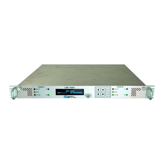
Chapter 1. INTRODUCTION 1.1 Overview Figure 1-1. Comtech EF Data LBC-4000 L-Band Up/Down Converter Comtech EF Data’s LBC-4000 L-Band Up/Down Converter System (Figure 1-1) is designed to interface legacy 70 MHz or 140 MHz equipment to tri-band or quad- band block converters. -
Page 24: Figure 1-2. Lbc-4000 Typical Application Block Diagram
LBC-4000 L-Band Up/Down Converter System MN/LBC4000.IOM Introduction Revision 5 Figure 1-2 shows the block diagram for a typical LBC-4000 L-Band Up/Down Converter System application. Figure 1-2. LBC-4000 Typical Application Block Diagram The LBC-4000 features: • Flexible configuration: Two IDU module bays allow for (1) Up Converter Module and (1) Down Converter Module;... -
Page 25: Converter Features
LBC-4000 L-Band Up/Down Converter System MN/LBC4000.IOM Introduction Revision 5 1.3 Converter Features 1.3.1 Physical Description The LBC-4000 features a 1RU-high (1.75”) 19-inch wide chassis that is designed for rack mounting into a standard 19-inch (48.26 cm) equipment rack. The unit may also be mounted into the rack using the provided slide mechanisms to allow service without removal from the rack. -
Page 26: Dimensional Envelope
LBC-4000 L-Band Up/Down Converter System MN/LBC4000.IOM Introduction Revision 5 1.3.2 Dimensional Envelope Dimensions are shown in inches and [millimeters]. Figure 1-3. LBC-4000 Dimensional Envelope 1–4... -
Page 27: Front Panel
LBC-4000 L-Band Up/Down Converter System MN/LBC4000.IOM Introduction Revision 5 1.3.3 Front Panel (TOP) Operating Position (BOTTOM) Service Position Figure 1-4. Front Panel View The LBC-4000 front panel (Figure 1-4) provides: Item 1 – Rack Handles These handles ease removal and replacement of the chassis into the user- provided rack enclosure. -
Page 28: Rear Panel
LBC-4000 L-Band Up/Down Converter System MN/LBC4000.IOM Introduction Revision 5 Lights GREEN when the module is operating as an UP CONVERTER. DOWN Lights GREEN when the module is operating as a DOWN CONVERTER. Item 4 – Vacuum Fluorescent Display (VFD) The VFD is an active display showing two lines of 24 characters each. It produces a blue light with adjustable brightness. -
Page 29: Figure 1-6. Rear Panel - Initially Released Chassis (Obsolete)
LBC-4000 L-Band Up/Down Converter System MN/LBC4000.IOM Introduction Revision 5 From left to right: Item 1 – ‘J2 | EXT REF IN’ Utility Connector Use this BNC female connector to supply a 5/10 MHz master reference to the entire chassis. Item 2 – ‘J4 | RF OUT/IN’ (part of IDU Up / Down Converter Module) Use this Type 'N' female connector as either the ‘CONV B’... - Page 30 LBC-4000 L-Band Up/Down Converter System MN/LBC4000.IOM Introduction Revision 5 Item 7 – Power Connection (part of Power Supply module) Use this Prime Power receptacle for connection to 90 to 125 VAC, or 205 to 240 VAC power sources. • The standard AC (Alternating Current) unit features an IEC-60320 Type...
-
Page 31: Chapter 2. Specifications
Chapter 2. SPECIFICATIONS 2.1 Physical and Environmental Specifications 2.1.1 Regulatory Compliance • “CE” as follows: o EN 50082-1 (EMC/Generic Immunity) o EN 55022 Class B (Emissions) o EN 55024 (Immunity) o EN 60950 (Safety) • FCC Part 15 Subpart B •... -
Page 32: Operational Altitude
LBC-4000 L-Band Up/Down Converter System MN/LBC4000.IOM Specifications Revision 5 2.1.5 Operational Altitude 10,000 ft above Mean Sea Level (MSL) 2.1.6 Shock Normal commercial shipping and handling 2.1.7 Front Panel Features 2.1.7.1 LED Monitoring Two sets of five Status LEDs – ‘CONV A’ and ‘CONV B’: •... -
Page 33: Modular Design
LBC-4000 L-Band Up/Down Converter System MN/LBC4000.IOM Specifications Revision 5 2.1.7.5 Modular Design (2) IDU Module bays (‘CONV A’ and ‘CONV B’) are located behind the drop-down front panel. 2.1.7.5.1 LBC-4000 L-Band Up Converter IDU Module • STANDARD: 70 MHz ±18 MHz Input Frequency •... -
Page 34: Lbc-4000 L-Band Down Converter Idu Module
LBC-4000 L-Band Up/Down Converter System MN/LBC4000.IOM Specifications Revision 5 2.1.7.5.2 LBC-4000 L-Band Down Converter IDU Module Input Frequency Range 950 MHz to 2000 MHz, 1 kHz steps • STANDARD: 70 MHz ±18 MHz Output Frequency • OPTIONAL: 140 MHz ±36 MHz Input/Output Impedance 50Ω... -
Page 35: Rf Connectors Access
LBC-4000 L-Band Up/Down Converter System MN/LBC4000.IOM Specifications Revision 5 2.1.8.2 RF Connectors Access • Standard (part of Up or Down Converter IDU Module): o (1X) ‘J4 | RF OUT/IN’ Type 'N' female connector provided for either the ‘CONV B’ L-Band output signal interface (with the Down Converter IDU installed) or the L-Band input signal interface (with the Up Converter IDU installed). -
Page 36: Serial Connectors
LBC-4000 L-Band Up/Down Converter System MN/LBC4000.IOM Specifications Revision 5 2.1.8.5 Serial Connectors • Summary Alarm: (1X) DB-9F (D-Subminiature) ‘P1 | Relay’ Utility Connector to access the Form C Alarms (relay closures). • Serial Remote Control Interface: (1X) DB-9F (D-Subminiature) ‘J1 | COM1’... -
Page 37: Chapter 3. Installation And Startup
Chapter 3. INSTALLATION STARTUP 3.1 Unpack and Inspect the Shipment Figure 3-1. Unpack and Inspect the Shipment 3–1... - Page 38 1. Keep all shipping materials. 2. Check the packing list to make sure the shipment is complete. 3. Inspect the equipment for damage. If damage exists, immediately contact the carrier and Comtech EF Data to submit a damage report. 4. Read the manual.
-
Page 39: Install The Unit Into A Rack Enclosure
Make sure there is proper air ventilation. Do not block the top of the rack or the presence of a rack blower. The air temperature inside the rack must never exceed 50°C (122°F). If there is any doubt, contact Comtech EF Data Product Support during normal business hours. 3–3... -
Page 40: Figure 3-2. Install The Unit Into A Rack Enclosure
LBC-4000 L-Band Up/Down Converter System MN/LBC4000.IOM Installation and Startup Revision 5 Feature Description Custom Rack Enclosure LBC-4000 chassis Standard Rack Shelving Rack Enclosure Threaded Front Rail (typical) Unit Front Panel User-supplied Screws Figure 3-2. Install the Unit into a Rack Enclosure... -
Page 41: Install The Optional Rear Support Brackets Kit
LBC-4000 L-Band Up/Down Converter System MN/LBC4000.IOM Installation and Startup Revision 5 3.2.1 Install the Optional Rear Support Brackets Kit Feature Description Back of unit Rack Enclosure Threaded Rear Mounting Rail (typical) Kit / Quantity Item CEFD P/N Description KT/6228-2 KT/6228-3... - Page 42 LBC-4000 L-Band Up/Down Converter System MN/LBC4000.IOM Installation and Startup Revision 5 Tools needed to install the optional KT/6228-2 (4”) or KT/6228-3 (10”) Brackets Kit: • A medium Phillips screwdriver • A 5/32-inch SAE Allen Wrench • An adjustable Crescent wrench.
-
Page 43: Install The Optional Rack Slide Set
LBC-4000 L-Band Up/Down Converter System MN/LBC4000.IOM Installation and Startup Revision 5 3.2.2 Install the Optional Rack Slide Set CEFD Part Number Description FP/SL0007 Bearingless Rack Slide Set – 22” FP/SL0008 Bearingless Rack Slide Set – 24” FP/SL0006 Bearingless Rack Slide Set – 26”... -
Page 44: Connect External Cables
Proceed to connect all external cables to the connectors outlined in the next chapter (Chapter 4. REAR PANEL CONNECTIONS). Should difficulties occur, call Comtech EF Data Product Support for assistance. 3.4 Connect Prime Power An IEC-60320 Type C13 (female) three-prong plug power cord for 90-125VAC or 205-240VAC power sources is provided with the converter. -
Page 45: Chapter 4. Rear Panel Connectors
Chapter 4. REAR PANEL CONNECTORS 4.1 Overview – Cabling Connection Types Comtech EF Data’s LBC-4000 L-Band Up/Down Converter System uses a number of different cables. Each cable type is typically dedicated to a specific mode of operation. 1) Not all of these operational interface types may be available. -
Page 46: Coaxial Cable Connections
(BOTTOM) Threaded Coupling Plug and Jack (Type ‘N’ Shown) Figure 4-1. Coaxial Connector Examples The types of coaxial cables used by Comtech EF Data are ‘BNC’, ‘TNC’, ‘N’, ‘F’, and ‘SMA’. Coaxial cables (plugs) and their mating connectors (jacks/sockets) are available in two coupling styles –... -
Page 47: Bnc
LBC-4000 L-Band Up/Down Converter System MN/LBC4000.IOM Rear Panel Connectors Revision 5 4.1.1.1 ‘BNC’ BNC plugs and jacks feature a Bayonet Coupling design. 4.1.1.2 ‘TNC’ TNC plugs and jacks feature a Threaded Coupling design similar to Type ‘N’, Type ‘F’ and Type ‘SMA’ connectors. -
Page 48: D-Subminiature Cable Connections
LBC-4000 L-Band Up/Down Converter System MN/LBC4000.IOM Rear Panel Connectors Revision 5 4.1.2 D-Subminiature Cable Connections Type ‘D’ Cable with Jack Screws Type ‘D’ Chassis Receptacles with Jack Nuts: (Female Shown) (TOP) Female (BOTTOM) Male Figure 4-2. D-Subminiature Connector Examples D-Subminiature connectors are also called Type ‘D’ or ‘D-Sub’ connectors. The cable plug and chassis receptacle each feature a D-shaped profile that interlock to ensure proper pin orientation and connector seating. -
Page 49: Usb Cable Connections
LBC-4000 L-Band Up/Down Converter System MN/LBC4000.IOM Rear Panel Connectors Revision 5 The plug for an RJ-45 or RJ-48 cable features a flexible tab. The RJ-45 or RJ-48 receptacle features a mating slot. This design configuration ensures a secure installation. Connection Instructions As shown in Figure 4-3 –... -
Page 50: Unit Connectors
LBC-4000 L-Band Up/Down Converter System MN/LBC4000.IOM Rear Panel Connectors Revision 5 4.2 Unit Connectors External cables are attached to connectors provided on the rear panel of the unit (Figure 4-5). Figure 4-5. LBC-4000 Rear Panel – Current Ethernet-ready Chassis with... -
Page 51: Table 4-1. '10/100 Ethernet' M&C Interface Connector Pinout
LBC-4000 L-Band Up/Down Converter System MN/LBC4000.IOM Rear Panel Connectors Revision 5 Item 3 – ‘J5 | IF IN/OUT’ (part of IDU Up / Down Converter Module) Use this ‘BNC’ female connector as either the ‘CONV B’ downconverted IF input signal (with the Down Converter IDU installed), or the upconverted IF output signal (with the Up Converter IDU installed). -
Page 52: Table 4-2. 'P1 | Relay' Pinout
LBC-4000 L-Band Up/Down Converter System MN/LBC4000.IOM Rear Panel Connectors Revision 5 Item 9 – ‘J7 | IF IN/OUT’ (part of IDU Up / Down Converter Module) Use this 'BNC' female connector as either the ‘CONV A’ downconverted IF input signal (with the Down Converter IDU installed), or the upconverted IF output signal (with the Up Converter IDU installed). -
Page 53: Power And Ground Connections
LBC-4000 L-Band Up/Down Converter System MN/LBC4000.IOM Rear Panel Connectors Revision 5 Table 4-5. ‘J1 | COM1’ EIA-232C Pinout Pin # Description – TD; Transmit Data RD; Receive Data – GND; Ground – – – – 4.2.2 Power and Ground Connections 4.2.2.1 Power Interface Module –... -
Page 54: Ac Operation - Connecting Prime Power
LBC-4000 L-Band Up/Down Converter System MN/LBC4000.IOM Rear Panel Connectors Revision 5 4.2.2.2 AC Operation – Connecting Prime Power Figure 4-8. Apply AC Power to the Unit Do these steps to apply AC power to the unit (Figure 4-8): 1. Plug the provided AC power cord female end into the unit. -
Page 55: Chassis Ground Interface
LBC-4000 L-Band Up/Down Converter System MN/LBC4000.IOM Rear Panel Connectors Revision 5 Note the following: • The DC (Direct Current) Filter Input Module input voltage is -48VDC nominal, -36VDC minimum, -72VDC maximum. • Power Module Manufacturer: TE Connectivity P/N 6DAF1 (Comtech EF Data P/N 506-0015-002). -
Page 56: Applying Power To The Lbc-4000
LBC-4000 L-Band Up/Down Converter System MN/LBC4000.IOM Rear Panel Connectors Revision 5 Figure 4-10. Chassis Ground Interface Use the #10-32 stud (Item 12 in Figure 4-5 and Figure 4-10) for connecting a common chassis ground among equipment. 4.2.2.6 Applying Power to the LBC-4000 Figure 4-11. -
Page 57: Chapter 5. Firmware Update
If you need to update the firmware, you can apply the update to the LBC-4000 without having to remove it from operation. You may directly acquire the download from Comtech EF Data’s web site (www.comtechefdata.com), or receive the archive file by e-mail from Comtech EF Data Product Support. -
Page 58: About Firmware Numbers, File Versions, And Formats
5.1.2 About Firmware Numbers, File Versions, and Formats The Comtech EF Data Web site catalogues its firmware update archive files by product type (e.g., router, modem, etc.), the specific model, and optional hardware configurations. The LBC-4000 files are provided under “Home | Support | Software Downloads | Flash & Software Update Files | Converters | LBC-4000.”... -
Page 59: Prepare For The Firmware Download
LBC-4000 L-Band Up/Down Converter System MN/LBC4000.IOM Firmware Update Revision 5 5.2 Prepare for the Firmware Download 5.2.1 Required User-supplied Items You will need a Microsoft Windows-based PC equipped with available serial and Ethernet ports, a compatible Web browser (e.g., Internet Explorer), and a terminal emulator program (e.g., Tera Term or HyperTerminal). -
Page 60: Use The Lbc-4000 Front Panel To Get The Management Ip Address And Firmware Information
LBC-4000 L-Band Up/Down Converter System MN/LBC4000.IOM Firmware Update Revision 5 5.2.3.1 Use the LBC-4000 Front Panel to Get the Management IP Address and Firmware information Chapter 6. FRONT PANEL OPERATION Using the unit front panel: • You may view find the factory-assigned Management IP Address within the CONFIG ... -
Page 61: Use The Serial Interface To Find The Firmware Information
“Next Reboot Image” – as shown in this example: 2. Write down your firmware information for further reference or to provide to Comtech EF Data Product support. 5.2.3.3 Use the Serial Interface to Find the Firmware Information Chapter 8. SERIAL INTERFACE OPERATION Use your terminal emulator program to execute remote queries with the LBC-4000. -
Page 62: Make A Temporary Folder (Subdirectory) On The User Pc
LBC-4000 L-Band Up/Down Converter System MN/LBC4000.IOM Firmware Update Revision 5 5.2.4 Make a Temporary Folder (Subdirectory) on the User PC The temporary folder is where you store the firmware archive download. There are several ways you can make a temporary folder on a Windows PC: •... -
Page 63: Use Windows Explorer To Make A Folder
LBC-4000 L-Band Up/Down Converter System MN/LBC4000.IOM Firmware Update Revision 5 5.2.4.2 Use Windows Explorer to Make a Folder Do these steps: 1. Left-double-click the Windows Explorer icon on the Windows Desktop. 2. Depending in your Windows OS version: select File > New > Folder, or click your Folder Destination (e.g., Windows (C:) and then New Folder to... -
Page 64: Use Windows Command-Line Or Command Prompt To Make A Folder
LBC-4000 L-Band Up/Down Converter System MN/LBC4000.IOM Firmware Update Revision 5 5.2.4.4 Use Windows Command-line or Command Prompt to Make a Folder Select Start on the Windows taskbar and then do these steps: 1. Click Run... to open the Run window (or, depending on Windows OS version prior to Windows 95, click the MS-DOS Prompt icon from the Main Menu). -
Page 65: Download And Extract The Firmware Update Files
LBC-4000 L-Band Up/Down Converter System MN/LBC4000.IOM Firmware Update Revision 5 5.3 Download and Extract the Firmware Update Files Do these steps: 1. Go online to www.comtechefdata.com. 2. On the Main page – Under Support Information or the Support tab, select the Software Downloads hyperlink. - Page 66 LBC-4000 L-Band Up/Down Converter System MN/LBC4000.IOM Firmware Update Revision 5 o Click [Save] to download the EXE file to your Downloads folder. Once the download is complete the dialogue prompts you to either [Run] the self-extracting file, or to open or view the Windows Downloads folder for further action.
-
Page 67: Use Windows Desktop To View Folder Contents
LBC-4000 L-Band Up/Down Converter System MN/LBC4000.IOM Firmware Update Revision 5 • To use Windows Command-line or Command Prompt, see Section 5.3.1.2. After you confirm the firmware files are in the folder, proceed to Section 5.4 to upload the firmware update to the LBC-4000. -
Page 68: Steps To "Creflash" Upload The Firmware Files
LBC-4000 L-Band Up/Down Converter System MN/LBC4000.IOM Firmware Update Revision 5 • You download or otherwise have Comtech’s latest firmware files and the “CReflash” utility available on the User PC in an accessible temporary folder. 5.4.2 Steps to “CReflash” Upload the Firmware Files 1) The “CReflash”... -
Page 69: Steps To Ftp Upload The Firmware Files
LBC-4000 L-Band Up/Down Converter System MN/LBC4000.IOM Firmware Update Revision 5 • “Success!” 3. When done, click [Cancel] to exit CReflash. 5.4.3 Steps to FTP Upload the Firmware Files 1) Typical for all steps: “xxx.xxx.xxx.xxx” represents the assigned unit Management IP Address. -
Page 70: Steps To Complete The Firmware Update Procedure
LBC-4000 L-Band Up/Down Converter System MN/LBC4000.IOM Firmware Update Revision 5 5.4.4 Steps to Complete the Firmware Update Procedure • Chapter 6. FRONT PANEL OPERATION • Chapter 7. ETHERNET INTERFACE OPERATION Use the LBC-4000 front panel or the HTTP Interface to select the new firmware image. -
Page 71: Reboot The Unit
LBC-4000 L-Band Up/Down Converter System MN/LBC4000.IOM Firmware Update Revision 5 5.4.4.2 Reboot the Unit 5.4.4.2.1 Hard-reboot the Unit from the Rear Panel Typical for either the standard AC unit or the optional DC unit: 1. From the unit rear panel, switch the power OFF, and then turn the power back ON. - Page 72 LBC-4000 L-Band Up/Down Converter System MN/LBC4000.IOM Firmware Update Revision 5 Notes: 5–16...
-
Page 73: Chapter 6. Front Panel Operation
Chapter 6. FRONT PANEL OPERATION 6.1 Front Panel Overview You may fully control and monitor the LBC-4000 L-Band Up/Down Converter System from the front panel (Figure 6-1). Figure 6-1. Front Panel View 6.1.1 Power Up the LBC-4000 Figure 6-2. Available Power Switch For units as equipped, a prime power switch is mounted behind the front panel. -
Page 74: Led Indicators
LBC-4000 L-Band Up/Down Converter System MN/LBC4000.IOM Front Panel Operation Revision 5 Before turning on power to the unit, check to make sure that installation is complete, and verify that the LBC-4000 is connected to the proper prime power source, RF Input, and RF Output. -
Page 75: Vacuum Fluorescent Display (Vfd)
LBC-4000 L-Band Up/Down Converter System MN/LBC4000.IOM Front Panel Operation Revision 5 6.1.3 Vacuum Fluorescent Display (VFD) LBC-4000 VER #.#.# SN:012345678 See Figure 6-1, Item 2. The VFD is an active display showing two lines of 24 characters each. It produces a blue light with adjustable brightness. On most menu screens, you will see a flashing, solid-block cursor that blinks at a once- per-second rate. -
Page 76: Keypad
LBC-4000 L-Band Up/Down Converter System MN/LBC4000.IOM Front Panel Operation Revision 5 6.1.4 Keypad See Figure 6-1, Item 3. The keys for the current production unit keypad have a positive ‘click’ action that provides tactile feedback. Enter data via the keypad. -
Page 77: Front Panel Operation - Menu Matrix
LBC-4000 L-Band Up/Down Converter System MN/LBC4000.IOM Front Panel Operation Revision 5 6.2 Front Panel Operation – Menu Matrix Chapter Menu Screen Description Submenu Selections Sect. 6.2.1 Opening Screen – 6.2.2 Select (Main) Menu CONFIG; MONITOR; FAULTS; UTILITY CONV-A; CONV-B; REMOTE; REDUND;... -
Page 78: Opening Screen
LBC-4000 L-Band Up/Down Converter System MN/LBC4000.IOM Front Panel Operation Revision 5 6.2.1 Opening Screen LBC-4000 VER. #.#.# SN:012345678 The opening screen displays once you apply power to the unit. The top line identifies the unit model (e.g., LBC-4000). The bottom line displays the running Firmware Version (this number may vary) and the unit serial number. -
Page 79: Config:) Conv-A Or Conv-B (Converter Unit A Or Unit B)
LBC-4000 L-Band Up/Down Converter System MN/LBC4000.IOM Front Panel Operation Revision 5 Use the [][] keys to move the cursor to the desired choice. Press [ENT]. The function of each CONFIG submenu is as follows: • CONV-A, CONV-B Submenus – Displays the current configuration of the selected converter, including the frequency, attenuation, and slope. -
Page 80: Config Cnva Or Cnvb Atten/Slope
LBC-4000 L-Band Up/Down Converter System MN/LBC4000.IOM Front Panel Operation Revision 5 change its value. Repeat for all digits until you define the desired frequency. Select the Tx/Rx mute status: Use the [][] arrow keys on the bottom line to select the parameter. Use the [][] arrow keys to select ON or OFF. -
Page 81: Config:) Remote (Remote Control) Submenu
LBC-4000 L-Band Up/Down Converter System MN/LBC4000.IOM Front Panel Operation Revision 5 6.2.3.2 (CONFIG:) REMOTE (Remote Control) Submenu Remote Control: Local SERIAL ETHERNET Use the [][] arrow keys to select Local, SERIAL, or ETHERNET. Press [ENT]. 6.2.3.2.1 (REMOTE:) Local 1) When you select Local mode, remote monitoring is possible, but remote control is disabled. -
Page 82: Remote:) Ethernet
LBC-4000 L-Band Up/Down Converter System MN/LBC4000.IOM Front Panel Operation Revision 5 Finally, set the asynchronous character format. Use the [][] arrow keys to select the parameter, and then the [][] arrow keys to select the desired format (i.e., number of data bits; odd, even, or no parity; number of stop bits) as 8-N-1, 7-E-2, or 7-O-2. -
Page 83: Remote:) EthernetSnmp
LBC-4000 L-Band Up/Down Converter System MN/LBC4000.IOM Front Panel Operation Revision 5 6.2.3.2.3.3 (REMOTE:) ETHERNETSNMP COMMUNITIES TRAPS Use the [][] arrow keys to select COMMUNITIES or TRAPS. Press [ENT]. (REMOTE:) ETHERNETSNMPCOMMUNITIES SNMP Communities: READ WRITE TRAP Use the [][] arrow keys to select READ, WRITE, or TRAP. Press [ENT]. - Page 84 LBC-4000 L-Band Up/Down Converter System MN/LBC4000.IOM Front Panel Operation Revision 5 View or edit the SNMP Trap Community string. Use the [][] arrow keys to select a character, and then the [][] arrow keys to edit that character. Press [ENT].
-
Page 85: Config:) Redund (Redundancy) Submenu
LBC-4000 L-Band Up/Down Converter System MN/LBC4000.IOM Front Panel Operation Revision 5 6.2.3.3 (CONFIG:) REDUND (Redundancy) Submenu See Appendix B. REDUNDANCY OPERATION for detailed information about using the front panel menus for redundancy configuration and operation. This menu branch is functional in LOCAL MODE ONLY. -
Page 86: Config: Spect-Inv (Spectrum Inversion)
LBC-4000 L-Band Up/Down Converter System MN/LBC4000.IOM Front Panel Operation Revision 5 When an external reference oscillator is connected and set to other than 5 MHz or 10 MHz, the following screen appears: EXTERNAL REFERENCE FREQ MUST BE 5/10 MHz 6.2.3.5 CONFIG: SPECT-INV (Spectrum Inversion) -
Page 87: Select:) Faults Menu Branch
LBC-4000 L-Band Up/Down Converter System MN/LBC4000.IOM Front Panel Operation Revision 5 MON Ref Osc: Vtune=04.7 This screen displays raw voltage of the Ref Osc voltage tuning monitor. Use this screen for debugging purposes only. Monitor PS A: 12V=12.3 8V=08.2 5V=05.3 Monitor PS B: 12V=12.2... -
Page 88: Faults:) Stored
LBC-4000 L-Band Up/Down Converter System MN/LBC4000.IOM Front Panel Operation Revision 5 Faults: Conv-A ▲ iflo=OK rflo=OK temp=OK ▼ Faults: Conv-B ▲ iflo=OK rflo=OK temp=OK ▼ These screens show the active Conv-A and Conv-B Up and/or Down Converter IDU operating parameters fault states, where: •... -
Page 89: Faults:) Stored View
LBC-4000 L-Band Up/Down Converter System MN/LBC4000.IOM Front Panel Operation Revision 5 6.2.5.2.1 (FAULTS:) STORED VIEW If you select View and no faults exist in the stored faults log, the system displays this message: No Stored Faults. Otherwise, stored faults log entries display as per this example: Fault No. -
Page 90: Select:) Utility Menu Branch
LBC-4000 L-Band Up/Down Converter System MN/LBC4000.IOM Front Panel Operation Revision 5 6.2.6 (SELECT:) UTILITY Menu Branch TIME DISP FIRMWARE AID LAMPTEST RELAY SCRSAVER Use the [][] arrow keys to move the cursor to the desired choice. Press [ENT]. The function of each UTILITY submenu is as follows: •... -
Page 91: Utility:) Firmware Submenu
THESE MENUS ARE INTENDED FOR DIAGNOSTIC PURPOSES ONLY. DO NOT CHANGE AN IMAGE UNLESS OTHERWISE INSTRUCTED BY COMTECH EF DATA PRODUCT SUPPORT. This series of submenus permits you to view information about the DT-4500 internal firmware. The converter can store two complete firmware images, and you can select which image will be loaded the next time the unit reboots. -
Page 92: Firmware:) InfoImage#1/#2
LBC-4000 L-Band Up/Down Converter System MN/LBC4000.IOM Front Panel Operation Revision 5 6.2.6.3.1.2 (FIRMWARE:) INFOIMAGE#1/#2 Where ‘#X’ denotes the IMAGE#1 or IMAGE#2 firmware load, the IMAGE#1 and IMAGE#2 firmware load info screens are nested as follows: IMAGE#X: Bulk APP FPGA Use the [][] arrow keys to select Bulk, App, or FPGA. Press [ENT]. -
Page 93: Utility:) Aid (Application Identification String) Submenu
LBC-4000 L-Band Up/Down Converter System MN/LBC4000.IOM Front Panel Operation Revision 5 If the image that you select is already set as the designated Next Reboot Image, this message displays: THAT IMAGE IS ALREADY CURRENT. NO CHANGE MADE. You may repeat the task by instead selecting the alternate image. -
Page 94: Utility:) Lamptest Submenu
LBC-4000 L-Band Up/Down Converter System MN/LBC4000.IOM Front Panel Operation Revision 5 6.2.6.5 (UTILITY:) LAMPTEST Submenu Start Lamp Test? No Yes On the bottom line: Use the [][] arrow keys to select No or press [CLR] to exit this submenu. Otherwise, select Yes and press [ENT] to continue. The test... -
Page 95: Utility:) Scrsaver Theme
LBC-4000 L-Band Up/Down Converter System MN/LBC4000.IOM Front Panel Operation Revision 5 On the bottom line: Use the [][] arrow keys to select Theme or Time. Do NOT press [ENT] at this time. 6.2.6.7.1 (UTILITY:) SCRSAVER Theme Five screen saver themes are selectable. Each theme establishes a unique behavior for the screen saver when activated. -
Page 96: Utility:) Scrsaver Time
LBC-4000 L-Band Up/Down Converter System MN/LBC4000.IOM Front Panel Operation Revision 5 • The B-Board theme – This mode features a ‘marquee’ display that performs a ‘slow reveal’ from left to right, and then performs a ‘slow wipe’, again from left to right. -
Page 97: Chapter 7. Ethernet Interface Operation
Network Monitoring System (NMS) and a user-supplied Management Information Base (MIB) File Browser. CAUTION Comtech EF Data recommends use of the Ethernet-based SNMP interface for advanced users only. All other users are strongly encouraged to use the HTTP (Web Server) Interface for remote Monitor and Control (M&C) of the unit. -
Page 98: Prerequisites
MIB file names, the letter ‘x’ represents the revision of the file. 7.2.1.1 ComtechEFData Root MIB File • FW-0000235x.mib • ComtechEFData MIB file gives the root tree for all Comtech EF Data products and consists of only the following OID: o Name: comtechEFData o Type: MODULE-IDENTITY 7–2... -
Page 99: Lbc-4000 Common Mib File
LBC-4000 L-Band Up/Down Converter System MN/LBC4000.IOM Ethernet Interface Operation Revision 5 o OID: 1.3.6.1.4.1.6247 o Full path: iso(1).org(3).dod(6).internet(1).private(4).enterprises(1). comtechEFData(6247) o Module: ComtechEFData 7.2.1.2 LBC-4000 Common MIB File • FW-0020542x.mib • MIB file consists of all of the OID’s for management of the unit functions. -
Page 100: Snmp Traps
LBC-4000 L-Band Up/Down Converter System MN/LBC4000.IOM Ethernet Interface Operation Revision 5 7.2.3 SNMP Traps The LBC-4000 SNMP agent supports both SNMPv1 and v2. The Traps file needs to be compiled only if SNMPv1 traps are to be used. The LBC-4000 has the ability to send out SNMP traps when certain events occur in the unit. -
Page 101: Using Hyperterminal For Telnet Remote Control Operation
LBC-4000 L-Band Up/Down Converter System MN/LBC4000.IOM Ethernet Interface Operation Revision 5 The Telnet interface requires user login at the Administrator level and Read/Write level. Once logged into the Telnet interface as the Administrator, you have access to the optional serial-based Remote Control Interface. Figure 7-1 shows an example of the login process for remote control operation. -
Page 102: Configure Hyperterminal For Telnet Remote Control Operation
LBC-4000 L-Band Up/Down Converter System MN/LBC4000.IOM Ethernet Interface Operation Revision 5 7.3.1.1 Configure HyperTerminal for Telnet Remote Control Operation Figure 7-3. Configure HyperTerminal See Figure 7-3. Do these steps: 1. Make sure to define the Connect To Telnet connection properties correctly (File ... -
Page 103: Http (Web Server) Interface
LBC-4000 L-Band Up/Down Converter System MN/LBC4000.IOM Ethernet Interface Operation Revision 5 7.4 HTTP (Web Server) Interface A user-supplied web browser allows the full monitoring and control (M&C) of the LBC-4000 from its HTTP Interface. This non-secure embedded web application is designed for, and works best with, Microsoft Internet Explorer Version 5.5 or... -
Page 104: Figure 7-4. Http Interface "Splash" Page Example
LBC-4000 L-Band Up/Down Converter System MN/LBC4000.IOM Ethernet Interface Operation Revision 5 Failure to enter the correct User name and Password will return you to the Login window. Should you continue to specify an invalid User name or Password, the message “You do not have security privilege to access this area.”... -
Page 105: Http Interface Features
LBC-4000 L-Band Up/Down Converter System MN/LBC4000.IOM Ethernet Interface Operation Revision 5 7.4.2 HTTP Interface Features 7.4.2.1 Menu Tree Figure 7-5 Illustrates the menu hierarchy for the HTTP Interface. It features four navigation tabs (shown in blue). Primary page hyperlinks (grey) grant access to individual web pages. -
Page 106: Action Buttons
LBC-4000 L-Band Up/Down Converter System MN/LBC4000.IOM Ethernet Interface Operation Revision 5 have editable fields, action buttons and read-only displays for a specific function. 7.4.2.4 Action Buttons Action buttons are important in the HTTP Interface. Click an action button to do one of these tasks: •... -
Page 107: Http Interface Page Examples And Descriptions
LBC-4000 L-Band Up/Down Converter System MN/LBC4000.IOM Ethernet Interface Operation Revision 5 7.5 HTTP Interface Page Examples and Descriptions See Chapter 6. FRONT PANEL OPERATION for detailed descriptions of the configuration and monitoring features available throughout this interface. The page figures provided in this section are intended for reference only. -
Page 108: Home | Contact
LBC-4000 L-Band Up/Down Converter System MN/LBC4000.IOM Ethernet Interface Operation Revision 5 7.5.1.2 Home | Contact For all product support, please call: +1.240.243.1880 +1.866.472.3963 (toll free USA) Figure 7-7. ‘Home | Contact’ Page 7–12... -
Page 109: Home | Support
Figure 7-8. ‘Home | Support’ Page The ‘Home | Support’ page (Figure 7-8) uses Simple Mail Transport Protocol (SMTP) to send e-mail to Comtech EF Data Product Support: cdmipsupport@comtechefdata.com Enter the Contact Information and compose a message in the Problem Report text window. -
Page 110: Admin (Administration)
LBC-4000 L-Band Up/Down Converter System MN/LBC4000.IOM Ethernet Interface Operation Revision 5 7.5.2 Admin (Administration) Pages The ‘Admin’ pages are available only to users who have logged in using the Administrator Name and Password. Click the Admin tab, and then select the Access or SNMP hyperlink to continue. - Page 111 LBC-4000 L-Band Up/Down Converter System MN/LBC4000.IOM Ethernet Interface Operation Revision 5 MAC Address – The MAC Address is read-only. It is set at the factory to a guaranteed unique address. It cannot be changed. Click [Change IP Address]. Click [Reset] to revert to the previously assigned IP...
-
Page 112: Admin | Snmp
LBC-4000 L-Band Up/Down Converter System MN/LBC4000.IOM Ethernet Interface Operation Revision 5 7.5.2.2 Admin | SNMP Sect. 7.2 SNMP Interface The Administrator must use this page to manage the SNMP (Simple Network Management Protocol) settings. Figure 7-10. ‘Admin | SNMP’ Page Simple Network Management –... -
Page 113: Config (Configuration)
LBC-4000 L-Band Up/Down Converter System MN/LBC4000.IOM Ethernet Interface Operation Revision 5 7.5.3 Config (Configuration) Pages Click the Config tab, and then select the Conv A, Conv B, Ref, Utility, Redundancy, or Serial hyperlink to continue. 7.5.3.1 Config | Conv A / B Pages Use this page to configure the communications, operations, and alarms/faults handling for the Converter A or Converter B IDU modules. - Page 114 LBC-4000 L-Band Up/Down Converter System MN/LBC4000.IOM Ethernet Interface Operation Revision 5 Converter A / Converter B Frequency in MHz – Enter an operating RF Frequency (if the converter is a Ku- Band down converter) in the range of 10950 to 12750 MHz; otherwise, this field displays as N/A.
-
Page 115: Config | Ref
LBC-4000 L-Band Up/Down Converter System MN/LBC4000.IOM Ethernet Interface Operation Revision 5 7.5.3.2 Config | Ref Use this page for monitor and control of the optional external reference oscillator. Figure 7-12. ‘Config | Ref’ Page Reference Oscillator External Reference Freq – This read-only item displays the operational value of the external reference oscillator (i.e., 5 MHz or 10 MHz) is displayed here. -
Page 116: Config | Utility
LBC-4000 L-Band Up/Down Converter System MN/LBC4000.IOM Ethernet Interface Operation Revision 5 7.5.3.3 Config | Utility Use this page to configure a variety of converter operating parameters. Figure 7-13. ‘Config | Utility’ Page Date Enter a date in the form MM/DD/YY (where MM = month [01 to 12], DD = day [01 to 31], and YY = year [00 to 99]). - Page 117 LBC-4000 L-Band Up/Down Converter System MN/LBC4000.IOM Ethernet Interface Operation Revision 5 Current Active Firmware Image This read-only section identifies the selected Current Active Firmware Image. In this example, Image 2 is the Current Active Firmware Image. Next Reboot Image Use the drop-down menu to select Image 1 or 2. Press [Submit] when done.
-
Page 118: Config | Redundancy
LBC-4000 L-Band Up/Down Converter System MN/LBC4000.IOM Ethernet Interface Operation Revision 5 7.5.3.4 Config | Redundancy See Appendix A. REDUNDANT SYSTEM OPERATION for the functional description of this page. Use this page to configure the LBC-4000’s Redundancy Switch Mode. Figure 7-14. ‘Config | Redundancy’ Page... -
Page 119: Config | Serial
LBC-4000 L-Band Up/Down Converter System MN/LBC4000.IOM Ethernet Interface Operation Revision 5 7.5.3.5 Config | Serial Use this page to configure LBC-4000 operating parameters over the EIA-485/232 serial interface. Figure 7-15. Config | Serial page Serial Use the drop-down menu to select the operating serial mode as RS-485 or RS-232. -
Page 120: Status
LBC-4000 L-Band Up/Down Converter System MN/LBC4000.IOM Ethernet Interface Operation Revision 5 7.5.4 Status Pages Use these pages to review operational statistics, status windows, and the stored faults table. Click the Status tab, and then select the Summary or Faults hyperlink to continue. - Page 121 LBC-4000 L-Band Up/Down Converter System MN/LBC4000.IOM Ethernet Interface Operation Revision 5 Parameter Status Product identification (i.e., CID/AID, serial and model numbers), active firmware, software image information, and other operational configuration information is provided here. Converter A / Converter B Status This section identifies the converter installed in each module slot (BUC or BDC) and each module’s associated RF conversion band and frequency, attenuation...
-
Page 122: Status | Faults
LBC-4000 L-Band Up/Down Converter System MN/LBC4000.IOM Ethernet Interface Operation Revision 5 7.5.4.2 Status | Faults Use this read-only page to review the current stored faults. Figure 7-17. ‘Status | Faults’ Page This page features a scrollable window that displays the unread stored faults log in sequential, date-stamped format. -
Page 123: Overview
Chapter 8. SERIAL INTERFACE OPERATION 8.1 Overview Serial-based Remote Product Management of the LBC-4000 L-Band Up/Down Converter System is available using the rear panel ‘J1 COM1’ port. This interface is either an EIA-485 multi-drop bus (for the control of many devices) or an EIA-232 connection (for the control of a single device). -
Page 124: Eia-485
LBC-4000 L-Band Up/Down Converter System MN/LBC4000.IOM Serial Interface Operation Revision 5 browser (for use of the LBC-4000 HTTP Interface). The LBC-4000 Management IP Address has been noted using the • serial interface. (The firmware information (i.e., revision letters, version numbers, etc.) as shown may differ from your setup.) 8.1.2... -
Page 125: Remote Commands And Queries Overview
LBC-4000 L-Band Up/Down Converter System MN/LBC4000.IOM Serial Interface Operation Revision 5 8.1.3 EIA-232 With this simpler configuration, the Controller device is connected directly to the Target via a two-wire-plus-ground connection. Controller-to-Target data is carried, via EIA-232 electrical levels, on one conductor, while the Target-to- Controller data is carried on the other conductor. -
Page 126: Address Delimiter
LBC-4000 L-Band Up/Down Converter System MN/LBC4000.IOM Serial Interface Operation Revision 5 Typical for EIA-232 or EIA-485 applications, the permissible range of values is from 0001 to 9999. Each block converter module has its own address: Module Address LBC-4000 Base Block Converter A... -
Page 127: Error Response
LBC-4000 L-Band Up/Down Converter System MN/LBC4000.IOM Serial Interface Operation Revision 5 defines the command configuration parameters that are issued to the Target. For example, the Controller-to-Target command “<0001/MUT_A_ON{cr}” means ‘turn ON the mute function of Converter A’. 2. The ‘_’ underscore, when submitted Controller-to-Target without parameters, functions as a query. -
Page 128: End Of Packet
LBC-4000 L-Band Up/Down Converter System MN/LBC4000.IOM Serial Interface Operation Revision 5 8.2.1.7 End of Packet • Controller-to-Target: This is the Carriage Return character {CR} (ASCII code 13). • Target-to-Controller: This is the two-character sequence of Carriage Return and Line Feed {CR}{LF} (ASCII codes 13 and 10). This pairing shows the valid end of a packet. - Page 129 LBC-4000 L-Band Up/Down Converter System MN/LBC4000.IOM Serial Interface Operation Revision 5 Sect. Parameter Description 8.3.27 Redundancy Mode 8.3.28 Remote Mode 8.3.29 Retrieve Equipment Type 8.3.30 RET_y_ Retrieve Module Type 8.3.31 Retrieve Maintenance Status 8.3.32 Retrieve Utility Status 8.3.33 Set Auto/Manual Switching Mode 8.3.34...
-
Page 130: Aid (Application Identification)
LBC-4000 L-Band Up/Down Converter System MN/LBC4000.IOM Serial Interface Operation Revision 5 8.3.1 AID (Application Identification) Command or Query. Use “AID” to sets or return a name (also called the ‘Circuit ID’) for the unit or station. Controller-to-Target Arguments for Target-to-Controller... -
Page 131: Att (Attenuation Level)
LBC-4000 L-Band Up/Down Converter System MN/LBC4000.IOM Serial Interface Operation Revision 5 8.3.3 ATT (Attenuation Level) Command or query. Use “ATT” to set or return the attenuation level, in dB, in 0.1 dB steps. Controller-to-Target Arguments for Target-to-Controller Instruction Code and Qualifier... -
Page 132: Cas (Concise Alarm Status)
LBC-4000 L-Band Up/Down Converter System MN/LBC4000.IOM Serial Interface Operation Revision 5 8.3.5 CAS (Concise Alarm Status) Query only. Use “CAS” to return the Alarm Status for the unit. Controller-to-Target Arguments for Target-to-Controller Instruction Code and Qualifier Command or Description of Arguments... -
Page 133: Cmm (Configure Mute Mode)
LBC-4000 L-Band Up/Down Converter System MN/LBC4000.IOM Serial Interface Operation Revision 5 8.3.7 CMM (Configure Mute Mode) Command or Query. Use “CMM” to set or return the mute mode. Controller-to-Target Arguments for Target-to-Controller Instruction Code and Qualifier Command or Description of Arguments... -
Page 134: Cus (Concise Utility Status)
LBC-4000 L-Band Up/Down Converter System MN/LBC4000.IOM Serial Interface Operation Revision 5 8.3.9 CUS (Concise Utility Status) Query only. Use “CUS” to return a summarized version of the utility status. Controller-to-Target Arguments for Target-to-Controller Instruction Code and Qualifier Command or Description of Arguments... -
Page 135: Fre (Operating Frequency)
LBC-4000 L-Band Up/Down Converter System MN/LBC4000.IOM Serial Interface Operation Revision 5 8.3.12 FRE (Operating Frequency) Command or Query. Use “FRE” to set or return the operating frequency, in MHz. Controller-to-Target Arguments for Target-to-Controller Instruction Code and Qualifier Command or Description of Arguments... -
Page 136: Frm (Retrieve Firmware Number)
LBC-4000 L-Band Up/Down Converter System MN/LBC4000.IOM Serial Interface Operation Revision 5 8.3.14 FRM (Retrieve Firmware Number) Query only. For use with current (Ethernet-ready) versions of the LBC-4000. Returns the firmware information for the unit. Controller-to-Target Arguments for Target-to-Controller Instruction Code and Qualifier... -
Page 137: Img (Select Boot Image)
LBC-4000 L-Band Up/Down Converter System MN/LBC4000.IOM Serial Interface Operation Revision 5 8.3.16 IMG (Select Boot Image) Command or Query. Set or return the firmware image to boot from at startup. Controller-to-Target Arguments for Target-to-Controller Instruction Code and Qualifier Command or... -
Page 138: Laa (List All Alarms)
LBC-4000 L-Band Up/Down Converter System MN/LBC4000.IOM Serial Interface Operation Revision 5 8.3.19 LAA (List All Alarms) Query only. Use “LAA” to return the list of stored alarms. Controller-to-Target Arguments for Target-to-Controller Instruction Code and Qualifier Command or Description of Arguments... -
Page 139: Mut (Mute State)
Return in the form ONL_y where: ONL_y alphabetic y=A (Conv A) or B (Conv B) 8.3.24 PNM (Retrieve Part Number) Query only. Returns the factory-assigned Comtech EF Data part number for the Unit, Conv A, or Conv B. Controller-to-Target Arguments for Target-to-Controller... -
Page 140: Ras (Retrieve Alarm Status)
LBC-4000 L-Band Up/Down Converter System MN/LBC4000.IOM Serial Interface Operation Revision 5 8.3.25 RAS (Retrieve Alarm Status) Query only. Use “RAS” to return the alarm status for the unit. Controller-to-Target Arguments for Target-to-Controller Instruction Code and Qualifier Command or Description of Arguments... -
Page 141: Red (Redundancy Mode)
LBC-4000 L-Band Up/Down Converter System MN/LBC4000.IOM Serial Interface Operation Revision 5 8.3.27 RED (Redundancy Mode) Command or query. Use “RED” to set or return the active redundancy mode. Controller-to-Target Arguments for Target-to-Controller Instruction Code and Qualifier Command or Response Description of Arguments... -
Page 142: Ret_Y_ (Retrieve Module Type)
LBC-4000 L-Band Up/Down Converter System MN/LBC4000.IOM Serial Interface Operation Revision 5 8.3.30 RET_y_ (Retrieve Module Type) Query only. Use “RET” with an argument to return the operating frequency and function (i.e., up/down) of the selected module. Controller-to-Target Arguments for Target-to-Controller... -
Page 143: Rus (Retrieve Utility Status)
LBC-4000 L-Band Up/Down Converter System MN/LBC4000.IOM Serial Interface Operation Revision 5 8.3.32 RUS (Retrieve Utility Status) Legacy Query only. Use “RUS” to return the operating utility features for the unit. Controller-to-Target Arguments for Target-to-Controller Instruction Code and Qualifier Command or... -
Page 144: Sbr (Remote Baud Rate)
LBC-4000 L-Band Up/Down Converter System MN/LBC4000.IOM Serial Interface Operation Revision 5 8.3.35 SBR (Remote Baud Rate) Command or Query. Use “SBR” to set or return the serial baud rate of the unit. Controller-to-Target Arguments for Target-to-Controller Instruction Code and Qualifier... -
Page 145: Sro (Reference Oscillator Adjustment)
LBC-4000 L-Band Up/Down Converter System MN/LBC4000.IOM Serial Interface Operation Revision 5 8.3.38 SRO (Reference Oscillator Adjustment) Command or Query. Use “SRO” to set or return the reference oscillator adjustment level. Controller-to-Target Arguments for Target-to-Controller Instruction Code and Qualifier Command or... -
Page 146: Tim (Set Rtc [Real-Time Clock] Time)
LBC-4000 L-Band Up/Down Converter System MN/LBC4000.IOM Serial Interface Operation Revision 5 Query Example: <0001/SSN_U{cr} >0001/SSN_U_012345678{cr}{lf} 8.3.41 TIM (Set RTC [Real-Time Clock] Time) Command or Query. Use “TIM” to set or return the real-time clock time. Controller-to-Target Arguments for Target-to-Controller Instruction Code and Qualifier... -
Page 147: Appendix A. Up/Down Converter Idu Module Removal/Re-Installation
Appendix A. UP/DOWN CONVERTER IDU MODULE REMOVAL/RE-INSTALLATION A.1 Overview This appendix illustrates the procedure required to remove and re-install an IDU module for the LBC-4000 Up/Down Converter System into any LBC-4000 chassis (Figure A-1 shows a legacy serial-only chassis with the top cover removed for clarity). -
Page 148: Idu Module Removal Procedure
LBC-4000 L-Band Up/Down Converter System MN/LBC4000.IOM Appendix A Revision 5 A.2 IDU Module Removal Procedure Do these steps: Step Task Loosen the front panel thumbscrews (by turning counterclockwise), and drop the front panel to access the IDU modules. Use a Phillip’s®-head screwdriver to... - Page 149 LBC-4000 L-Band Up/Down Converter System MN/LBC4000.IOM Appendix A Revision 5 Step Task Remove the Reference Cable: Unlock (by turning counterclockwise), and then remove the connector from its socket. Remove the Ribbon (Data) Cable: Unlock, and then remove, the ribbon cable connector from its socket.
- Page 150 LBC-4000 L-Band Up/Down Converter System MN/LBC4000.IOM Appendix A Revision 5 Step Task Remove the IDU module from the chassis: Use the module front handle to slide it straight out until it is free and clear of its internal chassis guides.
-
Page 151: Idu Module Re-Installation Procedure
LBC-4000 L-Band Up/Down Converter System MN/LBC4000.IOM Appendix A Revision 5 A.3 IDU Module Re-Installation Procedure Do these steps: Step Task Install the replacement IDU module. Make sure to engage the module guide rails within the chassis. Then, use the module front handle to slide... - Page 152 LBC-4000 L-Band Up/Down Converter System MN/LBC4000.IOM Appendix A Revision 5 Connect the Reference Cable: Install the cable connector onto the socket, and then lock the cable into operating position (by turning clockwise). Install the IDU module into the chassis: Use the module front...
- Page 153 LBC-4000 L-Band Up/Down Converter System MN/LBC4000.IOM Appendix A Revision 5 Secure the module in place: Use a Phillip’s®-head screwdriver to tighten (by turning clockwise) the captive machine screws. Swing the front panel back into operating position and finger- tighten the three thumbscrews (by turning clockwise).
- Page 154 LBC-4000 L-Band Up/Down Converter System MN/LBC4000.IOM Appendix A Revision 5 Notes: A–8...
-
Page 155: Appendix B. Redundancy Operation
Appendix B. REDUNDANCY OPERATION B.1 Overview The redundancy hardware option is required for use of the LBC-4000 L-Band Up/Down Converter System in 1:1 redundant operations. You may optionally configure the LBC-4000 for redundant system operation. This appendix provides detailed information for cabling and otherwise configuring the LBC-4000 for 1:1 redundancy. -
Page 156: Lbc-4000 Front Panel Operations
Revision 5 • BNC connections, where applicable, use 50Ω BNC male-to-male cables. • Comtech EF Data recommends that all Type ‘N’ to Type ‘SMA’ cable connections are best accomplished using a Type ‘N’ male to Type ‘SMA’ female adapter, then using Type ‘SMA’ female-to-female cables. -
Page 157: Figure B-3. Lbc-4000 Front Panel
LBC-4000 L-Band Up/Down Converter System MN/LBC4000.IOM Appendix B Revision 5 Figure B-3. LBC-4000 Front Panel Item 1 – Rack Handles These handles ease removal and replacement of the chassis into the user- provided rack enclosure. Item 2 – Available Power Switch Use this switch, when installed, to turn power to the unit on or off. -
Page 158: Using The Front Panel Menus
LBC-4000 L-Band Up/Down Converter System MN/LBC4000.IOM Appendix B Revision 5 B.2.1 Using the Front Panel Menus Chapter 6. FRONT PANEL OPERATION B.2.1.1 Main Menu The Main Menu for the LBC-4000 appears as follows: CONFIG MONITOR FAULTS UTILITY Use the [][] keys to move the cursor to the desired choice. Press [ENT]. The function of each menu branch is as follows: •... -
Page 159: Config:) Redund (Redundancy
LBC-4000 L-Band Up/Down Converter System MN/LBC4000.IOM Appendix B Revision 5 • REDUND Submenu – The selections here allow you to identify the redundancy state and mode. SEE SECT. B.2.1.3 TO USE THIS SUBMENU IN REDUNDANCY OPERATIONS. • REFADJ Submenu – This screen allows you to adjust the reference oscillator. -
Page 160: Gain Offset For Redundant Operations
LBC-4000 L-Band Up/Down Converter System MN/LBC4000.IOM Appendix B Revision 5 To force the redundant unit into standby mode, use the [][] arrow keys to select YES or NO. Press [ENT]. Note that, if you attempt to access this menu and the Redundancy State is... -
Page 161: Redundancy Operations Using The Lbc-4000 Http Interface
LBC-4000 L-Band Up/Down Converter System MN/LBC4000.IOM Appendix B Revision 5 B.3 Redundancy Operations Using the LBC-4000 HTTP Interface Chapter 7. ETHERNET INTERFACE OPERATION Use the LBC-4000 HTTP Interface ‘Config | Redundancy’ page to configure the LBC-4000’s Redundancy Switch Mode. Figure B-4. ‘Config | Redundancy’ page Click [Refresh] to update the page with its latest operating parameters. -
Page 162: Redundancy Operations Using Serial Remote Control
LBC-4000 L-Band Up/Down Converter System MN/LBC4000.IOM Appendix B Revision 5 Force Backup Use the drop-down menu to select Yes, and then click [Change] to force the redundant unit into standby mode. The last section on this page displays the read-only Online or Offline status for each converter. -
Page 163: Sam (Set Auto/Manual Switching Mode
LBC-4000 L-Band Up/Down Converter System MN/LBC4000.IOM Appendix B Revision 5 B.4.3 SAM (Set Auto/Manual Switching Mode) Command or Query. Use “SAM” to set or return the operating redundancy switching mode as Automatic or Manual. Controller-to-Target Arguments for Target-to-Controller Instruction Code and Qualifier... - Page 164 LBC-4000 L-Band Up/Down Converter System MN/LBC4000.IOM Appendix B Revision 5 Notes: B–10...
- Page 166 2114 85281 WEST TH STREET TEMPE ARIZONA 480 • 333 • 2200 PHONE 480 • 333 • 2161...