Table of Contents
Advertisement
Quick Links
DT-4500 Series
C- and Ku-Band Down Converters
Installation and Operation Manual
Firmware Ver. 1.3.4 and Higher
Part Number MN/DT4500.IOM / CD-MNDT4500
Revision 2
IMPORTANT NOTE: The information contained in this document supersedes all previously published
information regarding this product. Product specifications are subject to change without prior notice.
Part Number MN/DT4500.IOM / CD-MNDT4500 Revision 2
Advertisement
Table of Contents
Troubleshooting

Related Manuals for Comtech EF Data DT-4500 Series


Summary of Contents for Comtech EF Data DT-4500 Series
- Page 1 DT-4500 Series C- and Ku-Band Down Converters Installation and Operation Manual Firmware Ver. 1.3.4 and Higher Part Number MN/DT4500.IOM / CD-MNDT4500 Revision 2 IMPORTANT NOTE: The information contained in this document supersedes all previously published information regarding this product. Product specifications are subject to change without prior notice.
- Page 2 Copyright © 2016 Comtech EF Data. All rights reserved. Printed in the USA. Comtech EF Data, 2114 West 7th Street, Tempe, Arizona 85281 USA, 480.333.2200, FAX: 480.333.2161...
-
Page 3: Table Of Contents
European Union Low Voltage Directive (LVD) (2006/95/EC) ......xxi European Union RoHS Directive (2002/95/EC) ..........xxi European Union Telecommunications Terminal Equipment Directive (91/263/EEC) ....................xxi CE Mark ......................xxii Product Support ................... xxii Comtech EF Data Headquarters ..............xxii Warranty Policy .................... xxii... - Page 4 DT-4500 Series C- and Ku-Band Down Converters MN/DT4500.IOM / CD-MNDT4500 Table of Contents Revision 2 Limitations of Warranty ................... xxiii Exclusive Remedies..................xxiv CHAPTER 1. INTRODUCTION ............1–1 Overview ..................1–1 Functional Description ..............1–2 1.2.1 Applications ..................1–3 1.2.2 RF Signal Conversion ................1–4 1.2.3 Monitor &...
- Page 5 DT-4500 Series C- and Ku-Band Down Converters MN/DT4500.IOM / CD-MNDT4500 Table of Contents Revision 2 2.1.8.3 Ethernet Connector................ 2–4 2.1.8.4 Serial Connectors ................2–4 2.1.8.5 Removable “Personality” Modules ..........2–4 2.1.8.5.1 IOM (Input/Output Module) Assemblies ......... 2–4 2.1.8.5.2 PSM (Polarity Switch Module) Assemblies ......2–5 2.1.8.5.3 TSM (Transmit Switch Module) Assemblies ......
- Page 6 DT-4500 Series C- and Ku-Band Down Converters MN/DT4500.IOM / CD-MNDT4500 Table of Contents Revision 2 2.2.9.8 IF Bandwidth ................2–10 2.2.10 Group Delay ..................2–10 2.2.10.1 Linear.................... 2–10 2.2.10.2 Parabolic ..................2–10 2.2.10.3 Ripple ................... 2–10 2.2.11 Phase Noise ..................2–11 2.2.11.1 DT-4503, DT-4503/C, DT-4503/D ..........
- Page 7 DT-4500 Series C- and Ku-Band Down Converters MN/DT4500.IOM / CD-MNDT4500 Table of Contents Revision 2 4.2.1.1.2 AC Operation – Apply AC Power ..........4–9 4.2.1.2 Power Interface Module – Optional -48VDC Unit ......4–10 4.2.1.2.1 DC Operation – Replace the Fuses ......... 4–10 4.2.1.2.2 DC Operation –...
- Page 8 DT-4500 Series C- and Ku-Band Down Converters MN/DT4500.IOM / CD-MNDT4500 Table of Contents Revision 2 5.4.1 Important Considerations ..............5–11 5.4.2 Steps to “CReflash” Upload the Firmware Files ......... 5–12 5.4.3 Steps to FTP Upload the Firmware Files ..........5–13 5.4.4 Steps to Complete the Firmware Update Procedure ......
- Page 9 DT-4500 Series C- and Ku-Band Down Converters MN/DT4500.IOM / CD-MNDT4500 Table of Contents Revision 2 6.2.3.5 (CONFIG:) COLDSTART Submenu ..........6–17 6.2.4 (SELECT:) MONITOR Menu Branch ............. 6–17 6.2.5 (SELECT:) FAULTS Menu Branch ............6–18 6.2.5.1 (FAULTS:) CURRENT ..............6–18 6.2.5.2 (FAULTS:) STORED .................
- Page 10 DT-4500 Series C- and Ku-Band Down Converters MN/DT4500.IOM / CD-MNDT4500 Table of Contents Revision 2 7.3.1 Using HyperTerminal for Telnet Remote Control Operation ....7–5 7.3.1.1 Configure HyperTerminal for Telnet Remote Control Operation ... 7–6 HTTP (Web Server) Interface ............. 7–7 7.4.1 HTTP Interface User Login ..............
- Page 11 DT-4500 Series C- and Ku-Band Down Converters MN/DT4500.IOM / CD-MNDT4500 Table of Contents Revision 2 8.2.3 Ethernet (100BASE-TX) ................ 8–2 Access Methods ................8–3 8.3.1 Direct (Physical) Access ................ 8–3 8.3.2 Indirect (Virtual) Access ............... 8–3 Addresses ..................8–4 8.4.1 Physical Address ................... 8–4 8.4.2 Virtual Address ..................
- Page 12 DT-4500 Series C- and Ku-Band Down Converters MN/DT4500.IOM / CD-MNDT4500 Table of Contents Revision 2 8.7.2.4 TPS (Time Protocol Server) ............8–12 8.7.2.5 LRS (Local / Remote Status) ............8–12 8.7.2.6 MAC (Media Access Control Address).......... 8–13 8.7.2.7 IPA (IP Address) ................8–13 8.7.2.8 IPG (IP Gateway) ................
- Page 13 DT-4500 Series C- and Ku-Band Down Converters MN/DT4500.IOM / CD-MNDT4500 Table of Contents Revision 2 8.7.5 Status Queries ..................8–27 8.7.5.1 RCS (Configuration Status) ............8–27 8.7.5.2 RMS (Maintenance Status) ............8–27 8.7.5.3 RUS (Utility Status) ............... 8–28 8.7.5.4 RAS (Alarm Status) ............... 8–28 8.7.5.5 SAS (Summary Alarm Status) ............
-
Page 14: Tables
DT-4500 Series C- and Ku-Band Down Converters MN/DT4500.IOM / CD-MNDT4500 Table of Contents Revision 2 A.4.2 Redundant System Configuration Using the DT-4500 HTTP Interface ......................A–14 A.4.3 Offset Adjustment ................A–16 Redundancy Systems – Converter Management ....... A–16 APPENDIX B. MAINTENANCE AND TROUBLESHOOTING .... B–1 Overview .................. -
Page 15: Figures
Figure 4-3. RJ-45/RJ-48 Connector Example ............4–5 Figure 4-4. USB Connector Examples ..............4–6 Figure 4-5. DT-4500 Series Rear and Front Panels (DT-4503 Current Production Chassis shown) ..................... 4–7 Figure 4-6. DT-4500 Series Rear Panel – Initially Released Chassis (OBSOLETE) (with RSM) .................... - Page 16 DT-4500 Series C- and Ku-Band Down Converters MN/DT4500.IOM / CD-MNDT4500 Table of Contents Revision 2 Figure 7-4. HTTP Interface “Splash” Page Example ..........7–8 Figure 7-5. HTTP Interface Menu Tree (FW Ver. 1.3.4) ........7–9 Figure 7-6. ‘Home | Home’ Page ..............7–11 Figure 7-7.
-
Page 17: Preface
Further, Comtech EF Data reserves the right to make changes in the specifications of the products described in this manual at any time without notice and without obligation to notify any person of such changes. -
Page 18: Conventions And References
Patents and Trademarks See all of Comtech EF Data's Patents and Patents Pending at http://patents.comtechefdata.com. Comtech EF Data acknowledges that all trademarks are the property of the trademark owners. Warnings, Cautions, Notes, and References A WARNING indicates a potentially hazardous situation that, if not avoided, could result in death or serious injury. -
Page 19: Recommended Standard Designations
DT-4500 Series C- and Ku-Band Down Converters MN/DT4500.IOM Preface Revision 2 Recommended Standard Designations Electronic Industries Association (EIA) designations supersede Recommended Standard (RS) designations. Reference to the old RS designations may appear where it might concern actual text (e.g., RS-232) displayed on the product panels and on screens or pages in the Serial Remote or HTTP (Web Server) Interfaces. -
Page 20: European Union Radio Equipment And Telecommunications Terminal
DT-4500 Series C- and Ku-Band Down Converters MN/DT4500.IOM Preface Revision 2 MORE THAN 95% RELATIVE HUMIDITY. • UNPRESSURIZED ALTITUDES OF MORE THAN 3048 METRES (10,000 FEET). • EXCESSIVE DUST. • FLAMMABLE GASES. • CORROSIVE OR EXPLOSIVE ATMOSPHERES. European Union Radio Equipment and Telecommunications Terminal Equipment (R&TTE) Directive (1999/5/EC) and EN... -
Page 21: European Union Low Voltage Directive (Lvd) (2006/95/Ec)
DT-4500 Series C- and Ku-Band Down Converters MN/DT4500.IOM Preface Revision 2 • Use Type 'D' connectors that have back-shells with continuous metallic shielding. • Type ‘D’ cabling must have a continuous outer shield (either foil or braid, or both). The shield must be bonded to the back-shell. -
Page 22: Ce Mark
Comtech EF Data for the warranty period specific to the product purchased. For equipment under warranty, the owner is responsible for freight to Comtech EF Data and all related customs, taxes, tariffs, insurance, etc. Comtech EF Data is responsible for the freight charges only for return of the equipment from the factory to the owner. -
Page 23: Limitations Of Warranty
The warranty does not apply to any part of a product that has been installed, altered, repaired, or misused in any way that, in the opinion of Comtech EF Data Corporation, would affect the reliability or detracts from the performance of any... -
Page 24: Exclusive Remedies
The remedies provided herein are the buyer’s sole and exclusive remedies. Comtech EF Data shall not be liable for any direct, indirect, special, incidental, or consequential damages, whether based on contract, tort, or any other legal theory. -
Page 25: Chapter 1. Introduction
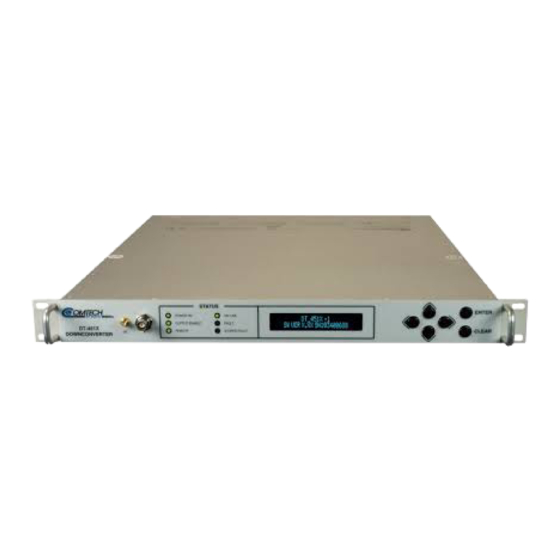
1.1 Overview Figure 1-1. DT-4500 Series Down Converters (DT-4503 shown) Comtech EF Data’s DT-4500 Series C- and Ku-Band Down Converters (Figure 1-1) are designed for the transmission of SCPC, DAMA and TDMA signals in communication systems or satellite downlink data systems. These converters are also used in communications system applications with full transponder HDTV and analog TV. -
Page 26: Functional Description
• Monitor & Control Assembly • Removable “Personality” Module (IOM, PSM, TSM, EQM, or RSM installs into rear chassis slot) • Reference Oscillator Assembly • Sum Loop Module • Power Supply Assembly Figure 1-2. DT-4500 Series Down Converter Physical Configuration 1–2... -
Page 27: Applications
DT-4500 Series C- and Ku-Band Down Converters MN/DT4500.IOM Introduction Revision 2 1.2.1 Applications The DT-4500 is a down converter. It converts the input RF frequency to an output IF frequency. The DT-4500 operates over the RF frequency range with a typical gain of 35 dB. -
Page 28: Rf Signal Conversion
RF Signal Conversion Figure 1-3. Typical Functional Block Diagram (DT-4512 shown) Figure 1-3 depicts the operational block diagram for a typical DT-4500 Series Down Converter in single thread (standalone) applications. See Appendix A. REDUNDANT SYSTEM OPERATION for more information about the DT-4500’s use in redundant applications. -
Page 29: Monitor & Control
DT-4500 Series C- and Ku-Band Down Converters MN/DT4500.IOM Introduction Revision 2 Using the example of a DT-4512 Ku-Band Down Converter: RF signal processing is accomplished when the RF input of 12200 to 12750 MHz, at a typical level of -45 dBm, is mixed in the first mixer with a 13280 to 13830 MHz synthesizer signal from a multiplier, in 125 KHz fine tuning steps. -
Page 30: Down Converter Features
DT-4500 Series C- and Ku-Band Down Converters MN/DT4500.IOM Introduction Revision 2 1.3 Down Converter Features 1.3.1 Physical Description The DT-4500 features a 1RU-high (1.75”) 19-inch wide chassis that is designed for rack mounting into a standard 19-inch (48.26 cm) equipment rack. The unit may also be mounted into the rack using the provided slide mechanisms to allow service without removal from the rack. -
Page 31: Dimensional Envelope
DT-4500 Series C- and Ku-Band Down Converters MN/DT4500.IOM Introduction Revision 2 1.3.2 Dimensional Envelope Dimensions are shown in inches and [millimeters]. Figure 1-4. DT-4500 Series Down Converter Dimensional Envelope 1–7... -
Page 32: Front Panel
DT-4500 Series C- and Ku-Band Down Converters MN/DT4500.IOM Introduction Revision 2 1.3.3 Front Panel (TOP) Initially Released Chassis (BOTTOM) Current Production Unit Figure 1-5. Front Panel View (DT-4503 Shown) The DT-4500 front panel (Figure 1-5) provides, from left to right): Item 1 –... - Page 33 DT-4500 Series C- and Ku-Band Down Converters MN/DT4500.IOM Introduction Revision 2 POWER ON Lights GREEN when prime power is applied to the unit. RECEIVE (INITIALLY RELEASED CHASSIS) OUTPUT ENABLE (CURRENT PRODUCTION UNIT) Lights AMBER when the transmit function is operational.
-
Page 34: Rear Panel
DT-4500 Series C- and Ku-Band Down Converters MN/DT4500.IOM Introduction Revision 2 Item 4 – Keypad The keypads for the initially-released chassis and the current production unit differ as follows: (LEFT) “Square” Button Keypad – Initially Released Chassis (RIGHT) “Round” Button Keypad – Current Production Unit The keys for the current production unit keypad have a positive ‘click’... -
Page 35: Figure 1-7. Rear Panel (With Rsm) - Initially Released Chassis (Obsolete)
DT-4500 Series C- and Ku-Band Down Converters MN/DT4500.IOM Introduction Revision 2 available on these legacy products. Figure 1-7. Rear Panel (with RSM) – Initially Released Chassis (OBSOLETE) From left to right: Item 1 – Power Connection (part of Power Supply module) •... - Page 36 Switch Module (TSM), Equalizer Module (EQM), or Receive Switch Module (RSM). The converter RF, IF, and High-Speed Bus (HSB) connectors are integral to the installed module. Contact Comtech EF Data Product Support for further information about the available modules. Also see: • Chapter 2. SPECIFICATIONS •...
-
Page 37: Chapter 2. Specifications
Chapter 2. SPECIFICATIONS Comtech EF Data publication DT-4572 X-Band Down Converter Installation and Operation Manual (CEFD P/N MN/DT4572.IOM) documents the X-Band version of this product. These specifications are typical for all C- and Ku-Band versions of this product unless noted. -
Page 38: Mean Time Between Failures (Mtbf)
DT-4500 Series C- and Ku-Band Down Converters MN/DT4500.IOM Specifications Revision 2 2.1.3 Mean Time Between Failures (MTBF) • 49,740 hrs as calculated • >100,000 hrs based on field experience 2.1.4 Temperature Range • Operating: 32° to 122° F (0° to 50° C) •... -
Page 39: Vacuum Fluorescent Display (Vfd)
DT-4500 Series C- and Ku-Band Down Converters MN/DT4500.IOM Specifications Revision 2 • FAULT (RED) • STORED FAULT (RED) 2.1.7.3 Vacuum Fluorescent Display (VFD) 2 lines, 24 characters per line. 2.1.7.4 Keypad Six Keys: (LEFT), (RIGHT), (UP), (DOWN), ENTER, CLEAR 2.1.8... -
Page 40: Grounding
Connector to access the Form C Alarms (relay closures). • Serial Remote Control Interface: (1X) DB-9F (D-Subminiature) ‘J1 | COM1’ EIA-232/EIA-485 (2-Wire/4-Wire) connector. 2.1.8.5 Removable “Personality” Modules Contact Comtech EF Data Product Support for information about using the available “personality” modules. 2.1.8.5.1 IOM (Input/Output Module) Assemblies Impedance... -
Page 41: Psm (Polarity Switch Module) Assemblies
DT-4500 Series C- and Ku-Band Down Converters MN/DT4500.IOM Specifications Revision 2 Impedance CEFD P/N Comments (Ohms) AS/0101-21 UT-4518 w/Isolator, Type ‘SMA’ AS/0101-23 UT-4514/F w/Isolator, Type ‘SMA’ AS/0101-29 UT-4514/F w/Isolator, Type ‘SMA’ AS/0101-39 DT-451X w/Isolator, Type ‘SMA’ AS/0101-40 DT-451X w/Isolator, Type ‘SMA’... -
Page 42: Rsm (Receive Switch Module) Assemblies
DT-451X w/Isolator, Type ‘SMA’ 2.2 Operational Specifications 2.2.1 Available Models / Operating Frequency Ranges Contact Comtech EF Data Product Support for your specific requirements. 2.2.1.1 C-Band Units • DT-4503: 3625 to 4200 MHz • DT-4503/C: 3400 to 4200 MHz • DT-4503/D: 3400 to 3700 MHz •... -
Page 43: Conversion
DT-4500 Series C- and Ku-Band Down Converters MN/DT4500.IOM Specifications Revision 2 • DT-4510/D: 10.70 to 11.70 GHz • DT-4511: 11.70 to 12.20 GHz • DT-4512: 12.20 to 12.75 GHz • DT-4512/E: 12.50 to 12.80 GHz • DT-4513: 10.95 to 12.75 GHz •... -
Page 44: Return Loss
IF Output 2.2.8.1 Level +20 dBm @ 1 dB Compression 2.2.8.2 Range Contact Comtech EF Data Product Support for your specific requirements. • STANDARD: 50 to 88 MHz or 104 to 176 MHz • OPTIONAL: 50 to 80 MHz or 100 to 180 MHz 2.2.8.3 Non-carrier Spurious... -
Page 45: Intermodulation
0 to 20 dB in 0.1 dB Steps 2.2.9.3 Gain Stability ± 0.25 dB/day 2.2.9.4 Ripple Contact Comtech EF Data Product Support for your specific requirements. • ±0.25 dB (±18 MHz) – OPTIONAL ±20 MHz • 0.75 dB (±36 MHz) – OPTIONAL ±40 MHz 2–9... -
Page 46: Slope
-80 dB Inband 2.2.9.7 AM to PM 0.1°/ dB for Output up to -5 dBm 2.2.9.8 IF Bandwidth Contact Comtech EF Data Product Support for your specific requirements. • STANDARD: 36 or 72 MHz • OPTIONAL: 40 or 80 MHz 2.2.10 Group Delay... -
Page 47: Phase Noise
DT-4500 Series C- and Ku-Band Down Converters MN/DT4500.IOM Specifications Revision 2 2.2.11 Phase Noise 2.2.11.1 DT-4503, DT-4503/C, DT-4503/D Parameter Limit (dBc/Hz) Typical (dBc/Hz) 100 Hz 1 KHz 10 KHz 100 KHz -105 -109 1 MHz -120 -124 2.2.11.2 DT-4510, DT-4510/D, DT-4511, DT-4512, DT-4512/E... - Page 48 DT-4500 Series C- and Ku-Band Down Converters MN/DT4500.IOM Specifications Revision 2 Notes: 2–12...
-
Page 49: Chapter 3. Installation And Startup
Chapter 3. INSTALLATION STARTUP 3.1 Unpack and Inspect the Shipment Figure 3-1. Unpack and Inspect the Shipment The DT-4500 Series C- or Ku-Band Down Converter, its optional Installation and Operation Manual (available online at http://www.comtechefdata.com), its 3–1... - Page 50 1. Keep all shipping materials. 2. Check the packing list to make sure the shipment is complete. 3. Inspect the equipment for damage. If damage exists, immediately contact the carrier and Comtech EF Data to submit a damage report. 4. Read the manual.
-
Page 51: Install The Unit Into A Rack Enclosure
Make sure there is proper air ventilation. Do not block the top of the rack or the presence of a rack blower. The air temperature inside the rack must never exceed 50°C (122°F). If there is any doubt, contact Comtech EF Data Product Support during normal business hours. 3–3... -
Page 52: Figure 3-2. Install The Unit Into A Rack Enclosure
DT-4500 Series C- and Ku-Band Down Converters MN/DT4500.IOM Installation and Startup Revision 2 Feature Description Custom Rack Enclosure DT-45XX chassis Standard Rack Shelving Rack Enclosure Threaded Front Rail (typical) Unit Front Panel User-supplied Screws Figure 3-2. Install the Unit into a Rack Enclosure... -
Page 53: Install The Optional Rear Support Brackets Kit
DT-4500 Series C- and Ku-Band Down Converters MN/DT4500.IOM Installation and Startup Revision 2 3.2.1 Install the Optional Rear Support Brackets Kit Feature Description Back of unit Rack Enclosure Threaded Rear Mounting Rail (typical) Kit / Quantity Item CEFD P/N Description... - Page 54 DT-4500 Series C- and Ku-Band Down Converters MN/DT4500.IOM Installation and Startup Revision 2 Tools needed to install the optional KT/6228-2 (4”) or KT/6228-3 (10”) Brackets Kit: • A medium Phillips screwdriver • A 5/32-inch SAE Allen Wrench • An adjustable Crescent wrench.
-
Page 55: Install The Optional Rack Slide Set
DT-4500 Series C- and Ku-Band Down Converters MN/DT4500.IOM Installation and Startup Revision 2 3.2.2 Install the Optional Rack Slide Set If the converter is to be mounted on slides, install the provided bearingless rack slide set into the rack cabinet, and onto the sides of the DT-45XX. Use the hardware provided with the slide set that is determined to be appropriate for installation. -
Page 56: Connect Prime Power Connection
AC Prime power receptacle on the rear of the converter chassis. 3.4 Connect External Cables Proceed to connect all external cables to the connectors outlined in the next chapter (Chapter 4. FRONT AND REAR PANEL CONNECTIONS). Should difficulties occur, call Comtech EF Data Product Support for assistance. 3–8... -
Page 57: Overview - Cabling Connection Types
REAR PANEL CONNECTORS 4.1 Overview – Cabling Connection Types Comtech EF Data’s DT-4500 Series C- and Ku-Band Down Converters use a number of different cables. Each cable type is typically dedicated to a specific mode of operation. 1) Not all of these operational interface types may be available. -
Page 58: Coaxial Cable Connections
(BOTTOM) Threaded Coupling Plug and Jack (Type ‘N’ Shown) Figure 4-1. Coaxial Connector Examples The types of coaxial cables used by Comtech EF Data are ‘BNC’, ‘TNC’, ‘N’, ‘F’, and ‘SMA’. Coaxial cables (plugs) and their mating connectors (jacks/sockets) are available in two coupling styles –... -
Page 59: Type 'Bnc
DT-4500 Series C- and Ku-Band Down Converters MN/DT4500.IOM Front and Rear Panel Connectors Revision 2 4.1.1.1 Type ‘BNC’ BNC plugs and jacks feature a Bayonet Coupling design. 4.1.1.2 Type ‘TNC’ TNC plugs and jacks feature a Threaded Coupling design similar to Type ‘N’, Type ‘F,’... -
Page 60: Type 'Sma
DT-4500 Series C- and Ku-Band Down Converters MN/DT4500.IOM Front and Rear Panel Connectors Revision 2 4.1.1.5 Type ‘SMA’ Type ‘SMA’ connectors feature a Threaded Coupling design similar to Type ‘TNC’, Type ‘N’, and Type ‘F’ connectors. 4.1.2 D-Subminiature Cable Connections Type ‘D’... -
Page 61: Cable Connections
DT-4500 Series C- and Ku-Band Down Converters MN/DT4500.IOM Front and Rear Panel Connectors Revision 2 4.1.3 RJ-45, RJ-48 Cable Connections Figure 4-3. RJ-45/RJ-48 Connector Example The plug for an RJ-45 or RJ-48 cable features a flexible tab. The RJ-45 or RJ-48 receptacle features a mating slot. -
Page 62: Usb Cable Connections
DT-4500 Series C- and Ku-Band Down Converters MN/DT4500.IOM Front and Rear Panel Connectors Revision 2 4.1.4 USB Cable Connections (TOP) Type ‘A’ USB Plug and Receptacle (BOTTOM) Type ‘B’ USB Plug and Receptacle Figure 4-4. USB Connector Examples Universal Serial Bus connectors are also called USB connectors. A USB connection is used as a bus-type communications or power interface between peripheral devices. -
Page 63: Unit Connectors
(TOP) Rear Panel with Optional -48VDC Unit Power Interface (CENTER) Rear Panel with Standard AC Unit (with IOM) (BOTTOM) Front Panel Figure 4-5. DT-4500 Series Rear and Front Panels (DT-4503 Current Production Chassis shown) Figure 4-6. DT-4500 Series Rear Panel – Initially Released Chassis (OBSOLETE) (with RSM) 4–7... -
Page 64: Power Connections
DT-4500 Series C- and Ku-Band Down Converters MN/DT4500.IOM Front and Rear Panel Connectors Revision 2 4.2.1 Power Connections 4.2.1.1 Power Interface Module – Standard AC Unit Figure 4-7. Standard AC Power Module As shown in Figure 4-5 and Figure 4-7, the AC power interface module consists of the following components: Item 1 –... -
Page 65: Ac Operation - Apply Ac Power
DT-4500 Series C- and Ku-Band Down Converters MN/DT4500.IOM Front and Rear Panel Connectors Revision 2 As shown in Figure 4-7 and Figure 4-8: The unit rear panel features a fuse holder that is press-fit into the body of the IEC power module. -
Page 66: Power Interface Module - Optional -48Vdc Unit
DT-4500 Series C- and Ku-Band Down Converters MN/DT4500.IOM Front and Rear Panel Connectors Revision 2 4.2.1.2 Power Interface Module – Optional -48VDC Unit Figure 4-10. Optional DC Power Module As shown in Figure 4-5 and Figure 4-10, the DC power interface module consists of the following components: Item 1 –... -
Page 67: Dc Operation - Apply Power
DT-4500 Series C- and Ku-Band Down Converters MN/DT4500.IOM Front and Rear Panel Connectors Revision 2 4.2.1.2.2 DC Operation – Apply Power Figure 4-11. Apply DC Power to the Unit Do these steps to apply DC power to the unit (Figure 4-11): 1. -
Page 68: Operational Connections
The impedance is matched for 50Ω or 75Ω and provides an output level of 5 ±3 dBm. Item 6 – ‘Ethernet’ Ethernet Management Utility Port The DT-4500 Series Down Converter, as initially released, does not feature a rear panel ‘Ethernet’ port. Only current production units offer Ethernet Interface operation. -
Page 69: Table 4-1. 'Ethernet' M&C Interface Connector Pinout
DT-4500 Series C- and Ku-Band Down Converters MN/DT4500.IOM Front and Rear Panel Connectors Revision 2 Table 4-1. ‘Ethernet’ M&C Interface Connector Pinout Pin # Description Direction Item 7 – ‘J1 | COM1’ Serial Management Utility Connector Use this D-Sub 9-pin female (DB-9F) EIA-232/EIA-485 connector for Serial Interface operation. -
Page 70: Table 4-5. 'P1 | Relay' Pinout
DT-4500 Series C- and Ku-Band Down Converters MN/DT4500.IOM Front and Rear Panel Connectors Revision 2 Item 8 – ‘P1 | RELAY’ Utility Connector Use this D-Sub 9-pin female (DB-9F) connector to access the Form C Alarms (relay closures). The mating connector is a DB-9M connector. -
Page 71: Dt-4500 Series Cable Connections
4.2.3.1 DT-4500 Series Cable Connections Figure 4-15. DT-4500 Series Cabling Example (with RSM) Figure 4-15 provides a cabling connection example for the DT-4500 Series Down Converters. This example depicts use of a Receive Switch Module (RSM) in a standalone configuration – the module cabling requirements will vary. All other cabling to the available rear chassis connectors is identical across all applications. -
Page 72: Removable "Personality" Modules
Contact Comtech EF Data Product Support for complete details and specifications for the module(s) specific to your system. See Chapter 2. SPECIFICATIONS for the listings of available modules for use with the DT-4500 Series Down Converters and UT-4500 Series Up Converters. (TOP) Input/Output Switch Module (IOM) -
Page 73: Removable Module Connectors
DT-4500 Series C- and Ku-Band Down Converters MN/DT4500.IOM Front and Rear Panel Connectors Revision 2 4.2.4.1 Removable Module Connectors The module connector types vary depending on the operating band and impedance of the purchased unit: • The IF Input/Output and LP (Loop) In/Out connectors are typically female BNC connectors. -
Page 74: Removable Module Operation In Non-Redundant (Standalone) Applications
Front and Rear Panel Connectors Revision 2 The ‘J3 | HSB’ connector does not employ a “straight-through” cable assembly. Contact Comtech EF Data Product Support for detailed cabling instructions when cabling between converters in redundant applications. 4.2.4.2 Removable Module Operation in Non-Redundant... -
Page 75: Removable Module Operation In Redundant Applications
DT-4500 Series C- and Ku-Band Down Converters MN/DT4500.IOM Front and Rear Panel Connectors Revision 2 4.2.4.3 Removable Module Operation in Redundant Applications See Appendix A. REDUNDANT SYSTEM OPERATION for descriptions of the specific use of these various switch modules in redundant applications. - Page 76 DT-4500 Series C- and Ku-Band Down Converters MN/DT4500.IOM Front and Rear Panel Connectors Revision 2 Notes: 4–20...
-
Page 77: Chapter 5. Firmware Update
5.1 Firmware Overview Make sure to operate the DT-4500 with its latest available firmware. The DT-4500 Series C- or Ku-Band Down Converter is factory-shipped with its latest version of operating firmware. If you need to update the firmware, you can apply the update to the DT-4500 without having to remove it from operation. -
Page 78: About Firmware Numbers, File Versions, And Formats
5.1.2 About Firmware Numbers, File Versions, and Formats The Comtech EF Data Web site catalogues its firmware update archive files by product type (e.g., router, modem, etc.), the specific model, and optional hardware configurations. The DT-4500 files are provided under “Home | Support | Software Downloads | Flash &... -
Page 79: Prepare For The Firmware Download
DT-4500 Series C- and Ku-Band Down Converters MN/DT4500.IOM Firmware Update Revision 2 5.2 Prepare for the Firmware Download 5.2.1 Required User-supplied Items You will need a Microsoft Windows-based PC equipped with available serial and Ethernet ports, a compatible Web browser (e.g., Internet Explorer), and a terminal emulator program (e.g., Tera Term or HyperTerminal). -
Page 80: Use The Dt-4500 Front Panel To Get The Management Ip Address And Firmware Information
DT-4500 Series C- and Ku-Band Down Converters MN/DT4500.IOM Firmware Update Revision 2 5.2.3.1 Use the DT-4500 Front Panel to Get the Management IP Address and Firmware information Chapter 6. FRONT PANEL OPERATION Using the unit front panel: • You may view find the factory-assigned Management IP Address within the CONFIG ... -
Page 81: Use The Serial Interface To Find The Firmware Information
DT-4500 Series C- and Ku-Band Down Converters MN/DT4500.IOM Firmware Update Revision 2 • The ‘Summary’ section of the ‘Status | Summary’ page provides the firmware details – “FW Revision”, “Active Software Image”, and “Next Reboot Image” – as shown in this example: 2. -
Page 82: Use Windows Desktop To Make A Folder
DT-4500 Series C- and Ku-Band Down Converters MN/DT4500.IOM Firmware Update Revision 2 • To use Windows Explorer, see Section 5.2.4.2. • To use the Run and Browse windows, see Section 5.2.4.3. • To use Windows Command-line or the Command Prompt, see Section 5.2.4.4. -
Page 83: Use Windows Explorer To Make A Folder
DT-4500 Series C- and Ku-Band Down Converters MN/DT4500.IOM Firmware Update Revision 2 5.2.4.2 Use Windows Explorer to Make a Folder Do these steps: 1. Left-double-click the Windows Explorer icon on the Windows Desktop. 2. Depending in your Windows OS version: select File > New > Folder, or click your Folder Destination (e.g., Windows (C:) and then New Folder to... -
Page 84: Use Windows Command-Line Or Command Prompt To Make A Folder
DT-4500 Series C- and Ku-Band Down Converters MN/DT4500.IOM Firmware Update Revision 2 5.2.4.4 Use Windows Command-line or Command Prompt to Make a Folder Select Start on the Windows taskbar and then do these steps: 1. Click Run... to open the Run window (or, depending on Windows OS version prior to Windows 95, click the MS-DOS Prompt icon from the Main Menu). -
Page 85: Download And Extract The Firmware Update Files
DT-4500 Series C- and Ku-Band Down Converters MN/DT4500.IOM Firmware Update Revision 2 5.3 Download and Extract the Firmware Update Files Do these steps: 1. Go online to www.comtechefdata.com. 2. On the Main page – Under Support Information or the Support tab, select the Software Downloads hyperlink. - Page 86 DT-4500 Series C- and Ku-Band Down Converters MN/DT4500.IOM Firmware Update Revision 2 you to either [Run] the self-extracting file, or to open or view the Windows Downloads folder for further action. • For ZIP files: o Click [Open] to open the archive file. Use the WinZip features to select the files for extraction to your destination folder.
-
Page 87: Use Windows Desktop To View Folder Contents
DT-4500 Series C- and Ku-Band Down Converters MN/DT4500.IOM Firmware Update Revision 2 5.3.1.1 Use Windows Desktop to View Folder Contents From the Windows Desktop: 1. Double-left-click the Windows Explorer icon, and then double-left-click as needed to locate, and then open, the “temp” folder (directory) created earlier on the Windows Desktop. -
Page 88: Steps To "Creflash" Upload The Firmware Files
DT-4500 Series C- and Ku-Band Down Converters MN/DT4500.IOM Firmware Update Revision 2 5.4.2 Steps to “CReflash” Upload the Firmware Files 1) The “CReflash” utility is provided with the firmware download. Ver5x and earlier chassis units (i.e., non-Ethernet units) must use this procedure. -
Page 89: Steps To Ftp Upload The Firmware Files
DT-4500 Series C- and Ku-Band Down Converters MN/DT4500.IOM Firmware Update Revision 2 5.4.3 Steps to FTP Upload the Firmware Files 1) Typical for all steps: “xxx.xxx.xxx.xxx” represents the assigned unit Management IP Address. 2) Type all commands without quotes, and press Enter to execute. -
Page 90: Select The Boot Image
DT-4500 Series C- and Ku-Band Down Converters MN/DT4500.IOM Firmware Update Revision 2 5.4.4.1 Select the Boot Image 5.4.4.1.1 Use the Front Panel to Select the Boot Image Do these steps from the DT-4500 front panel: 1. Go to the UTILITY FIRMWARE SELECT menu branch. -
Page 91: Soft-Reboot The Unit From The Http Interface
DT-4500 Series C- and Ku-Band Down Converters MN/DT4500.IOM Firmware Update Revision 2 2. Verify the new firmware version has booted; for example, check the firmware version displayed on the DT-4500 front panel: DT_45XX –X SW VER X.X.X SN######### 5.4.4.2.2 Soft-reboot the Unit from the HTTP Interface Do these steps from the HTTP Interface ‘Config | Utility’... - Page 92 DT-4500 Series C- and Ku-Band Down Converters MN/DT4500.IOM Firmware Update Revision 2 Notes: 5–16...
-
Page 93: Chapter 6. Front Panel Operation
Chapter 6. FRONT PANEL OPERATION 6.1 Front Panel Overview You may fully control and monitor the DT-4500 Series C- or Ku-Band Down Converter from the front panel (Figure 6-1). (TOP) Initially Released Chassis (BOTTOM) Current Production Unit Figure 6-1. Front Panel View (DT-4503 Shown) -
Page 94: Power Up The Unit
DT-4500 Series C- and Ku-Band Down Converters MN/DT4500.IOM Front Panel Operation Revision 2 6.1.1 Power Up the Unit Before applying power, you should check to ensure that installation is complete. Verify that the converter is connected to the proper prime power source, RF Input, and IF Output. -
Page 95: Led Indicators
DT-4500 Series C- and Ku-Band Down Converters MN/DT4500.IOM Front Panel Operation Revision 2 6.1.2 LED Indicators The Light-Emitting Diode (LED) Indicators for the initially-released chassis and the current production unit differ as follows: (LEFT) LEDs – Initially Released Chassis (RIGHT) LEDs – Current Production Unit See Figure 6-1, Item 1.These six LED Indicators convey operational states as... -
Page 96: Vacuum Fluorescent Display (Vfd)
DT-4500 Series C- and Ku-Band Down Converters MN/DT4500.IOM Front Panel Operation Revision 2 6.1.3 Vacuum Fluorescent Display (VFD) The displays for the initially-released chassis and the current production unit differ as follows: (LEFT) Liquid Crystal Display (LCD) – Initially Released Chassis (RIGHT) Vacuum Fluorescent Display (VFD) –... -
Page 97: Keypad
DT-4500 Series C- and Ku-Band Down Converters MN/DT4500.IOM Front Panel Operation Revision 2 6.1.4 Keypad The keypads for the initially-released chassis and the current production unit differ as follows: (LEFT) “Square” Button Keypad – Initially Released Chassis (RIGHT) “Round” Button Keypad – Current Production Unit See Figure 6-1, Item 3. -
Page 98: Front Panel Operation - Menu Matrix
DT-4500 Series C- and Ku-Band Down Converters MN/DT4500.IOM Front Panel Operation Revision 2 6.2 Front Panel Operation – Menu Matrix Chapter Sect. Menu Screen Description Submenu Selections 6.2.1 Opening Screen – 6.2.2 Select (Main) Menu CONFIG; MONITOR; FAULTS; PRE-SELECTS; UTILITY 6.2.3... -
Page 99: Opening Screen
Press ENTER to display the Main Menu. Press CLEAR repeatedly from any nested screen to return to this screen. The screen shots provided throughout this chapter are applicable to all DT-4500 Series Down Converters. Any operational restrictions are noted. 6.2.2... -
Page 100: Select:) Config (Configuration) Menu Branch
DT-4500 Series C- and Ku-Band Down Converters MN/DT4500.IOM Front Panel Operation Revision 2 6.2.3 (SELECT:) CONFIG (Configuration) Menu Branch OUTPUT REMOTE REDUNDANCY FAULTRECOVERY COLDSTART Use the keys to move the cursor to the desired choice. Press ENTER. The function of each CONFIG submenu is as follows: •... -
Page 101: Config:) Output Submenu (Optional Dual If Rack Mount Converters)
6.2.3.1.1 (CONFIG:) OUTPUT Submenu (OPTIONAL DUAL IF RACK MOUNT CONVERTERS) Comtech EF Data provides the ability to switch the output IF frequency between 70 MHz and 140 MHz. For converters equipped with this optional hardware configuration, the (CONFIG:) OUTPUT submenu appears as follows: Frq=03627.125 MHz... -
Page 102: Config:) Remote (Remote Control) Submenu
DT-4500 Series C- and Ku-Band Down Converters MN/DT4500.IOM Front Panel Operation Revision 2 6.2.3.2 (CONFIG:) REMOTE (Remote Control) Submenu Remote Control: Local SERIAL ETHERNET Use the keys to select Local, SERIAL, or ETHERNET. Press ENTER. 6.2.3.2.1 (REMOTE:) Local 1) When you select Local mode, remote monitoring is possible, but remote control is disabled. -
Page 103: Remote:) Ethernet
(i.e., number of data bits; odd, even, or no parity; number of stop bits) are 8-N-1, 7-E-2, or 7-O-2. Press ENTER. 6.2.3.2.3 (REMOTE:) ETHERNET The DT-4500 Series C- and Ku-Band Down Converters, as initially released, do not feature a rear panel ‘Ethernet’ port. Only current production units offer Ethernet Interface operation. See Chapter 4. -
Page 104: Remote:) EthernetSnmp
DT-4500 Series C- and Ku-Band Down Converters MN/DT4500.IOM Front Panel Operation Revision 2 6.2.3.2.3.3 (REMOTE:) ETHERNETSNMP COMMUNITIES TRAPS Use the keys to select COMMUNITIES or TRAPS. Press ENTER. (REMOTE:) ETHERNETSNMPCOMMUNITIES SNMP Communities: READ WRITE TRAP Use the keys to select READ, WRITE, or TRAP. Press ENTER. - Page 105 DT-4500 Series C- and Ku-Band Down Converters MN/DT4500.IOM Front Panel Operation Revision 2 View or edit the SNMP Trap Community string. To edit, use the keys to select a character, and then use the keys to change that character. Press ENTER.
-
Page 106: Config:) Redundancy Submenu
DT-4500 Series C- and Ku-Band Down Converters MN/DT4500.IOM Front Panel Operation Revision 2 6.2.3.3 (CONFIG:) REDUNDANCY Submenu See Appendix A. REDUNDANT SYSTEM OPERATION for detailed information about using the front panel menus for redundancy configuration and operation. This menu branch is functional in LOCAL MODE ONLY. -
Page 107: Redundancy:) Auto/Manual
DT-4500 Series C- and Ku-Band Down Converters MN/DT4500.IOM Front Panel Operation Revision 2 Note the following: • With CONVERTER = #BU, the unit is set as the standby, or backup unit. This mode of operation is indicated on the right-hand side of the bottom line as 1:0#. -
Page 108: Redundancy:) Hsb
DT-4500 Series C- and Ku-Band Down Converters MN/DT4500.IOM Front Panel Operation Revision 2 On the bottom line, use the keys to navigate to the ACTIVATE BACKUP setting, and then use the keys to set toggle switchover as NO (i.e., no backup occurs at the defined operational threshold), or FORCE (i.e., switchover... -
Page 109: Config:) Faultrecovery Submenu
DT-4500 Series C- and Ku-Band Down Converters MN/DT4500.IOM Front Panel Operation Revision 2 6.2.3.4 (CONFIG:) FAULTRECOVERY Submenu Fault Recovery: Auto Use the keys to select Fault Recovery as Manual or Auto (automatic). Press ENTER. The default operation is Auto. -
Page 110: Select:) Faults Menu Branch
DT-4500 Series C- and Ku-Band Down Converters MN/DT4500.IOM Front Panel Operation Revision 2 Converter Temp = +30.0C ▲ IFLO Tuning = 0.38V ▼ Synth Tuning: Sum=0.32V ▲ Coarse=06.0V Fine=03.5V ▼ Press ENTER or CLEAR to continue. 6.2.5 (SELECT:) FAULTS Menu Branch The MASK selection is disabled in redundancy systems. -
Page 111: Faults:) Stored
DT-4500 Series C- and Ku-Band Down Converters MN/DT4500.IOM Front Panel Operation Revision 2 Conv Temperature = OK ▲ High Speed Bus = OK ▼ Use the keys to page between screens. Press ENTER or CLEAR to return to the previous menu. -
Page 112: Faults:) StoredClear-All
DT-4500 Series C- and Ku-Band Down Converters MN/DT4500.IOM Front Panel Operation Revision 2 Once the number of faults reaches 100, the 100 fault displays as “ER.” The stored faults remain in memory until you execute the CLEAR-ALL command. Press ENTER or CLEAR to return to the previous menu. -
Page 113: Pre-Selects:) Load
DT-4500 Series C- and Ku-Band Down Converters MN/DT4500.IOM Front Panel Operation Revision 2 Otherwise, when pre-selects are programmed and available, entries display as per this example: #03 LOAD PROGRAM CLEAR ▲ 03625.125 MHz 01.25 dB ▼ Use the keys to browse through the stored pre-selects (#01 through #32, as available). -
Page 114: Pre-Selects:) Clear
DT-4500 Series C- and Ku-Band Down Converters MN/DT4500.IOM Front Panel Operation Revision 2 6.2.6.3 (PRE-SELECTS:) CLEAR CLEAR deletes a previously programmed pre-select from the active memory slot. If a pre-select is present in the active memory slot, once you select CLEAR this... -
Page 115: Utility:) Time (Real-Time Clock) Submenu
DT-4500 Series C- and Ku-Band Down Converters MN/DT4500.IOM Front Panel Operation Revision 2 6.2.7.1 (UTILITY:) TIME (Real-Time Clock) Submenu This function follows Military time format (00 to 24 hours). Edit Real-Time Clock: HH:MM:SS MM/DD/YY Edit the time and date settings of the real-time clock. Use the keys to select a digit to edit, and then use the ... -
Page 116: Firmware:) Info
DT-4500 Series C- and Ku-Band Down Converters MN/DT4500.IOM Front Panel Operation Revision 2 6.2.7.3.1 (FIRMWARE:) INFO Firmware Info: BOOTROM IMAGE#1 IMAGE#2 Use the keys to select BOOTROM, IMAGE#1 or IMAGE#2. Press ENTER. to view the information. Typical for all nested screens, the top line identifies the firmware number. -
Page 117: Firmware:) Select
DT-4500 Series C- and Ku-Band Down Converters MN/DT4500.IOM Front Panel Operation Revision 2 (FIRMWARE:) INFOIMAGE#1/#2APP App#X: FW-0000203x X.X.X MM/DD/YY (FIRMWARE:) INFOIMAGE#1/#2FPGA FPGA#X: FW-0000204 X.X.X MM/DD/YY 6.2.7.3.2 (FIRMWARE:) SELECT Current Active Image: #1 Next Reboot Image: #1 #2 Use this submenu to select the Current Active Firmware Image. - Page 118 DT-4500 Series C- and Ku-Band Down Converters MN/DT4500.IOM Front Panel Operation Revision 2 destination or other aspects of the application that may be significant to operations. The default AID is "AID MESSAGE". At the “Edit AID Message?” prompt, use the keys to select No or Yes. Press ENTER.
-
Page 119: Utility:) Slope Submenu
DT-4500 Series C- and Ku-Band Down Converters MN/DT4500.IOM Front Panel Operation Revision 2 6.2.7.6 (UTILITY:) SLOPE Submenu Converter slope adjustment = 0.0 Set your converter slope adjustment value. Use the keys to select a digit, and then use the keys to change that digit. The default converter slope adjustment is 0.0, with allowable values from 0.0 to 1.0. - Page 120 DT-4500 Series C- and Ku-Band Down Converters MN/DT4500.IOM Front Panel Operation Revision 2 Notes: 6–28...
-
Page 121: Chapter 7. Ethernet Interface Operation
Windows-based PC to the DT-4500 rear panel ‘Ethernet’ 100BaseTX RJ-45 port. The DT-4500 Series C- or Ku-Band Down Converter, as initially released, does not feature a rear panel ‘Ethernet’ port. Only current production units offer Ethernet Interface operation. See Chapter 4. FRONT AND REAR PANEL CONNECTORS for more information. -
Page 122: Prerequisites
MIB file names, the letter ‘x’ represents the revision of the file. 7.2.1.1 ComtechEFData Root MIB File • FW-0000235x.mib • ComtechEFData MIB file gives the root tree for all Comtech EF Data products and consists of only the following OID: o Name: comtechEFData o Type: MODULE-IDENTITY 7–2... -
Page 123: Dt-45Xx Common Mib File
DT-4500 Series C- and Ku-Band Down Converters MN/DT4500.IOM Ethernet Interface Operation Revision 2 o OID: 1.3.6.1.4.1.6247 o Full path: iso(1).org(3).dod(6).internet(1).private(4).enterprises(1). comtechEFData(6247) o Module: ComtechEFData 7.2.1.2 DT-45xx Common MIB File • FW-0020205x.mib • MIB file consists of all of the OID’s for management of the unit functions. -
Page 124: Snmp Traps
DT-4500 Series C- and Ku-Band Down Converters MN/DT4500.IOM Ethernet Interface Operation Revision 2 7.2.3 SNMP Traps The DT-45xx SNMP agent supports both SNMPv1 and v2. The Traps file needs to be compiled only if SNMPv1 traps are to be used. -
Page 125: Using Hyperterminal For Telnet Remote Control Operation
DT-4500 Series C- and Ku-Band Down Converters MN/DT4500.IOM Ethernet Interface Operation Revision 2 The Telnet interface requires user login at the Administrator level and Read/Write level. Once logged into the Telnet interface as the Administrator, you have access to the optional serial-based Remote Control Interface. Figure 7-1 shows an example of the login process for remote control operation. -
Page 126: Configure Hyperterminal For Telnet Remote Control Operation
DT-4500 Series C- and Ku-Band Down Converters MN/DT4500.IOM Ethernet Interface Operation Revision 2 7.3.1.1 Configure HyperTerminal for Telnet Remote Control Operation Figure 7-3. Configure HyperTerminal See Figure 7-3. Do these steps: • Make sure to define the Connect To Telnet connection properties correctly (File ... -
Page 127: Http (Web Server) Interface
DT-4500 Series C- and Ku-Band Down Converters MN/DT4500.IOM Ethernet Interface Operation Revision 2 7.4 HTTP (Web Server) Interface A user-supplied web browser allows the full monitoring and control (M&C) of the DT-4500 from its HTTP Interface. This non-secure embedded web application is designed for, and works best with, Microsoft Internet Explorer Version 5.5 or... - Page 128 Figure 7-4. HTTP Interface “Splash” Page Example The appearance and function of all DT-4500 Series HTTP Interface pages are, for all purposes, identical to that of the DT-4503C HTTP Interface page examples that are featured throughout this chapter.
-
Page 129: Http Interface Features
DT-4500 Series C- and Ku-Band Down Converters MN/DT4500.IOM Ethernet Interface Operation Revision 2 7.4.2 HTTP Interface Features 7.4.2.1 Menu Tree Figure 7-5 Illustrates the menu hierarchy for the HTTP Interface. It features four navigation tabs (shown in blue). Primary page hyperlinks (grey) grant access to individual web pages. -
Page 130: Action Buttons
DT-4500 Series C- and Ku-Band Down Converters MN/DT4500.IOM Ethernet Interface Operation Revision 2 7.4.2.4 Action Buttons Action buttons are important in the HTTP Interface. Click an action button to do one of these tasks: • Click [Refresh] to see the latest page data. -
Page 131: Http Interface Page Examples And Descriptions
DT-4500 Series C- and Ku-Band Down Converters MN/DT4500.IOM Ethernet Interface Operation Revision 2 7.5 HTTP Interface Page Examples and Descriptions See Chapter 6. FRONT PANEL OPERATION for detailed descriptions of the configuration and monitoring features available throughout this interface. The page figures provided in this section are intended for reference only. -
Page 132: Home | Contact
DT-4500 Series C- and Ku-Band Down Converters MN/DT4500.IOM Ethernet Interface Operation Revision 2 7.5.1.2 Home | Contact For all product support, please call: +1.240.243.1880 +1.866.472.3963 (toll free USA) Figure 7-7. ‘Home | Contact’ Page 7–12... -
Page 133: Home | Support
Figure 7-8. ‘Home | Support’ Page The ‘Home | Support’ page (Figure 7-8) uses Simple Mail Transport Protocol (SMTP) to send e-mail to Comtech EF Data Product Support: cdmipsupport@comtechefdata.com Enter the Contact Information and compose a message in the Problem Report text window. -
Page 134: Admin (Administration)
DT-4500 Series C- and Ku-Band Down Converters MN/DT4500.IOM Ethernet Interface Operation Revision 2 7.5.2 Admin (Administration) Pages The ‘Admin’ pages are available only to users who have logged in using the Administrator Name and Password. Click the Admin tab, and then select the Access or SNMP hyperlink to continue. - Page 135 DT-4500 Series C- and Ku-Band Down Converters MN/DT4500.IOM Ethernet Interface Operation Revision 2 Click [Change IP Address]. Click [Reset] to revert to the previously assigned IP Gateway and IP Address/Range, System Account Access Information Admin, Read/Write, and Read Only Names and Passwords: The User name and Password can be any alphanumeric combination with a maximum length of 10 characters.
-
Page 136: Admin | Snmp
DT-4500 Series C- and Ku-Band Down Converters MN/DT4500.IOM Ethernet Interface Operation Revision 2 7.5.2.2 Admin | SNMP Sect. 7.2 SNMP Interface The Administrator must use this page to manage the SNMP (Simple Network Management Protocol) settings. Figure 7-10. ‘Admin | SNMP’ Page Simple Network Management –... -
Page 137: Config (Configuration)
DT-4500 Series C- and Ku-Band Down Converters MN/DT4500.IOM Ethernet Interface Operation Revision 2 7.5.3 Config (Configuration) Pages Click the Config tab, and then select the Converter, Ref, Pre-selects, Utility, or Redundancy hyperlink to continue. 7.5.3.1 Config | Converter Use this page to configure the communications, operations, and alarms/faults handling for the unit. - Page 138 DT-4500 Series C- and Ku-Band Down Converters MN/DT4500.IOM Ethernet Interface Operation Revision 2 Mute Use the drop-down list to set the Configuration Mute Mode as On or Off. Click [Change]. Carrier Mute Mode Use the drop-down list to set the Carrier Mute Mode as On or Off. Click [Change].
-
Page 139: Config | Ref
DT-4500 Series C- and Ku-Band Down Converters MN/DT4500.IOM Ethernet Interface Operation Revision 2 7.5.3.2 Config | Ref Use this page for monitor and control of the optional external reference oscillator. Figure 7-12. ‘Config | Ref’ Page Reference Oscillator External Reference Freq – This read-only item displays the operational value of the external reference oscillator (i.e., 5 MHz or 10 MHz) is displayed here. -
Page 140: Config | Pre-Selects
DT-4500 Series C- and Ku-Band Down Converters MN/DT4500.IOM Ethernet Interface Operation Revision 2 7.5.3.3 Config | Pre-selects Use this page to manage the converter operational pre-selects. Figure 7-13. ‘Config | Pre-selects’ Page Pre-Selects You may create (program) up to 32 operating configurations, and load (recall) them as needed. -
Page 141: Config | Utility
DT-4500 Series C- and Ku-Band Down Converters MN/DT4500.IOM Ethernet Interface Operation Revision 2 7.5.3.4 Config | Utility Use this page to configure a variety of converter operating parameters. Figure 7-14. ‘Config | Utility’ Page Date Enter a date in the form MM/DD/YY (where MM = month [01 to 12], DD = day [01 to 31], and YY = year [00 to 99]). - Page 142 DT-4500 Series C- and Ku-Band Down Converters MN/DT4500.IOM Ethernet Interface Operation Revision 2 Current Active Firmware Image This read-only section identifies the selected Current Active Firmware Image. In this example, Image 2 is the Current Active Firmware Image. Next Reboot Image – Use the drop-down list to select Image 1 or 2. Click [Submit].
-
Page 143: Config | Redundancy
DT-4500 Series C- and Ku-Band Down Converters MN/DT4500.IOM Ethernet Interface Operation Revision 2 7.5.3.5 Config | Redundancy See Appendix A. REDUNDANT SYSTEM OPERATION for the functional description of this page. Use this page to configure the DT-4500’s Redundancy Switch Mode. -
Page 144: Status
DT-4500 Series C- and Ku-Band Down Converters MN/DT4500.IOM Ethernet Interface Operation Revision 2 7.5.4 Status Pages Use these pages to review operational statistics, status windows, and the stored faults table. Click the Status tab, and then select the Summary or Faults hyperlink to continue. -
Page 145: Status | Faults
DT-4500 Series C- and Ku-Band Down Converters MN/DT4500.IOM Ethernet Interface Operation Revision 2 7.5.4.2 Status | Faults Use this read-only page to review the current stored faults. Figure 7-17. ‘Status | Faults’ Page This page features a scrollable window that displays the unread stored faults log in sequential, date-stamped format. - Page 146 DT-4500 Series C- and Ku-Band Down Converters MN/DT4500.IOM Ethernet Interface Operation Revision 2 Notes: 7–26...
-
Page 147: Overview
2) The pinout table for the rear panel ‘J1 | COM1’ connector is provided in Sect. 4.2.3 Operational Connections. Serial-based remote monitor and control (M&C) of the DT-4500 Series C- or Ku- Band Down Converter is possible by connecting the rear panel EIA-485/EIA-232C ‘J1 | COM1’... -
Page 148: Tia/Eia-232 (Rs-232)
DT-4500 Series C- and Ku-Band Down Converters MN/DT4500.IOM Serial Interface Operation Revision 2 communication, there are two separate, isolated, independent, differential- mode twisted pairs, each handling serial data in different directions. It is assumed that a 'Controller' device (a PC or dumb terminal) transmits data in a broadcast mode via one of the pairs. -
Page 149: Access Methods
DT-4500 Series C- and Ku-Band Down Converters MN/DT4500.IOM Serial Interface Operation Revision 2 username (default: comtech) and the password (default: comtech), the Telnet server accepts the same operands used by the serial remote interface. 8.3 Access Methods You may access a converter directly by using a physical address, or indirectly through a backup converter by using a virtual address. -
Page 150: Addresses
DT-4500 Series C- and Ku-Band Down Converters MN/DT4500.IOM Serial Interface Operation Revision 2 converters may be mixed on the cable as long as each has a unique device address. In order to indirectly address an online converter in the subsystem, you must provide a virtual address. -
Page 151: Ip Address
DT-4500 Series C- and Ku-Band Down Converters MN/DT4500.IOM Serial Interface Operation Revision 2 8.4.3 IP Address The IP address is a unique address on a network that supports Internet Protocol (i.e., IPv4). An example of a network address using IPv4 is 192.168.1.4 (factory default IP address). -
Page 152: Baud Rate
8.5.6 Bus Inactivity Requirement Comtech EF Data recommends that you provide a minimum of 50 milliseconds bus inactivity between the receipt of a response from an addressed converter and issuing the next command on the serial bus. -
Page 153: Message Structure
DT-4500 Series C- and Ku-Band Down Converters MN/DT4500.IOM Serial Interface Operation Revision 2 8.6 Message Structure The structure of a Command, Response, or Error Message is as follows: • Start Character • Device Address • Command or Response • End of Message String 8.6.1... -
Page 154: Confirmation Response
DT-4500 Series C- and Ku-Band Down Converters MN/DT4500.IOM Serial Interface Operation Revision 2 8.6.4 Confirmation Response A confirmation will change the start character, and echo the Device Address and Command. Any requested data is appended to the Command. • EXAMPLE: >DEV/COM_xxx{cr}{lf}] 8.6.5... -
Page 155: Remote Operation - Commands/Queries
DT-4500 Series C- and Ku-Band Down Converters MN/DT4500.IOM Serial Interface Operation Revision 2 8.7 Remote Operation – Commands/Queries 8.7.1 Command/Query Quick References 8.7.1.1 Utility Commands/Queries Quick Reference Sect. Item Description Syntax 8.7.2.1 Set Time <DEV/TIM_hh:mm:ss{cr} 8.7.2.2 Set Date <DEV/DAT_mm/dd/yy{cr} 8.7.2.3 Set Time Protocol <DEV/TPE_x{cr}... -
Page 156: Configuration Commands/Queries Quick Reference
DT-4500 Series C- and Ku-Band Down Converters MN/DT4500.IOM Serial Interface Operation Revision 2 8.7.1.2 Configuration Commands/Queries Quick Reference Sect. Item Description Syntax 8.7.3.1 Set Frequency <DEV/FRE_xxxxx.xxx{cr} 8.7.3.2 Set IF Frequency <DEV/IFF_xxx{cr} 8.7.3.3 Set Attenuation <DEV/ATT_xx.xx{cr} 8.7.3.4 Select Cold Start Mode <DEV/CLD_xxx{cr}... -
Page 157: Stored Alarm Queries Quick Reference
DT-4500 Series C- and Ku-Band Down Converters MN/DT4500.IOM Serial Interface Operation Revision 2 8.7.1.5 Stored Alarm Queries Quick Reference Sect. Item Description Syntax 8.7.6.1 Return Total Stored Alarms <DEV/TSA_{cr} 8.7.6.2 Clear All Stored Alarms <DEV/CAA_YES{cr} 8.7.6.3 List All Stored Alarms <DEV/LAA_{cr}... -
Page 158: Tpe (Time Protocol Enable)
DT-4500 Series C- and Ku-Band Down Converters MN/DT4500.IOM Serial Interface Operation Revision 2 8.7.2.3 TPE (Time Protocol Enable) Use TPE to set or return the Time Protocol. Description Details Set Time Protocol: <DEV/TPE_x{cr} where: x=0 Time protocol disabled 1 Time protocol enabled Confirmation: >DEV/TPE_x{cr}{lf}]... -
Page 159: Mac (Media Access Control Address)
DT-4500 Series C- and Ku-Band Down Converters MN/DT4500.IOM Serial Interface Operation Revision 2 8.7.2.6 MAC (Media Access Control Address) Use MAC to return the unique MAC address of the rear panel ‘Ethernet’ M&C port. Description Details Return MAC: <DEV/MAC_{cr} Confirmation: >DEV/MAC_xx-xx-xx-xx-xx-xx{cr}{lf}] where:... -
Page 160: Spa (Set Physical Address)
DT-4500 Series C- and Ku-Band Down Converters MN/DT4500.IOM Serial Interface Operation Revision 2 8.7.2.9 SPA (Set Physical Address) Use SPA to set the physical address of the unit. The default address is 001. Description Details Set Physical Address: <DEV/SPA_xxx{cr} where:... -
Page 161: Lcd (Set Lcd Brightness)
DT-4500 Series C- and Ku-Band Down Converters MN/DT4500.IOM Serial Interface Operation Revision 2 8.7.2.12 LCD (Set LCD Brightness) The LCD legacy command does not control any current production unit hardware. Its syntax is still supported to allow backwards compatibility with initially released chassis existing monitor and control applications. -
Page 162: Vfd (Vfd Brightness)
DT-4500 Series C- and Ku-Band Down Converters MN/DT4500.IOM Serial Interface Operation Revision 2 8.7.2.15 VFD (VFD Brightness) Use VFD to set or return the front panel brightness from 0% to 100% in 25% steps. The default VFD brightness is 100. -
Page 163: Ret (Equipment Type)
DT-4500 Series C- and Ku-Band Down Converters MN/DT4500.IOM Serial Interface Operation Revision 2 8.7.2.18 RET (Equipment Type) Use RET to query the read-only model number and software revision of the unit. Description Details Return Equipment Type: <DEV/RET_{cr} Confirmation: >DEV/RET_xxxxxxxxxx yyyyyyy{cr}{lf}] where:... -
Page 164: Frm (Firmware Information)
DT-4500 Series C- and Ku-Band Down Converters MN/DT4500.IOM Serial Interface Operation Revision 2 8.7.2.21 FRM (Firmware Information) Use FRM to query the firmware loaded in the current production unit. This includes firmware numbers, versions, and release dates. This query replaces the legacy FRW query. -
Page 165: Aid (Application Identification)
DT-4500 Series C- and Ku-Band Down Converters MN/DT4500.IOM Serial Interface Operation Revision 2 8.7.2.23 AID (Application Identification) Use AID to create a “free form” message. The intent is to identify the satellite, transponder, beam, destination or other aspects of the application that may be significant to operations. -
Page 166: Configuration Commands / Queries
DT-4500 Series C- and Ku-Band Down Converters MN/DT4500.IOM Serial Interface Operation Revision 2 8.7.3 Configuration Commands / Queries 8.7.3.1 FRE (Frequency) Use FRE to set or return the operating frequency. The default RF frequency of the unit is equal to its minimum operating frequency (RF... -
Page 167: Att (Attenuation)
DT-4500 Series C- and Ku-Band Down Converters MN/DT4500.IOM Serial Interface Operation Revision 2 8.7.3.3 ATT (Attenuation) Use ATT to set or return the attenuation value. The default value is 10.00 dB. Description Details Set Attenuation: <DEV/ATT_ yy.yy{cr} where: yy.yy = 00.00 to 25.00 dB in 0.25 dB steps (0.1 dB steps optional) Confirmation: >DEV/ATT_yy.yy{cr}{lf}]... -
Page 168: Cmm (Configure Mute Mode)
DT-4500 Series C- and Ku-Band Down Converters MN/DT4500.IOM Serial Interface Operation Revision 2 8.7.3.6 CMM (Configure Mute Mode) Use CMM to set or return the mute state of the unit during frequency changes. The default state is OFF (output is muted during frequency changes). When mute mode is ON, the unit will retain its mute state upon changing RF frequency. -
Page 169: Pgm (Program Pre-Select)
DT-4500 Series C- and Ku-Band Down Converters MN/DT4500.IOM Serial Interface Operation Revision 2 Description Details Set Fault Recovery: <DEV/AFR_xxx{cr} where: xxx = ON or 0FF Confirmation: >DEV/AFR_xxx{cr}{lf}] Return Status: <DEV/AFR_{cr} Confirmation: >DEV/AFR_xxx{cr}{lf}] 8.7.3.9 PGM (Program Pre-select) Use PGM to store up to 32 preset frequency and attenuation settings. -
Page 170: Clr (Clear Pre-Select Configuration)
DT-4500 Series C- and Ku-Band Down Converters MN/DT4500.IOM Serial Interface Operation Revision 2 8.7.3.11 CLR (Clear Pre-select Configuration) Use CLR to clear a single pre-select value. Description Details Clear a Preset: <DEV/CLR_nn{cr} where: nn = Pre-select Number (01 to 32) Confirmation: >DEV/CLR_nn_Cleared{cr}{lf}]... -
Page 171: Ict (Initialize Chain Command)
DT-4500 Series C- and Ku-Band Down Converters MN/DT4500.IOM Serial Interface Operation Revision 2 8.7.4.2 ICT (Initialize Chain Command) Use ICT to initialize each converter's chain position, including the backup converter. This command is allowed only when you are active in Redundancy Mode. -
Page 172: Fbu (Force Backup)
DT-4500 Series C- and Ku-Band Down Converters MN/DT4500.IOM Serial Interface Operation Revision 2 Description Details Switching Mode: <DEV/SAM_xx_y{cr} Confirmation: >DEV/SAM_xx_y{cr}{lf}] Automatic Status: <DEV/SAM_xx_{cr} Confirmation: >DEV/SAM_xx_y{cr}{lf}] where: xx = converter number 01 to 12 y = A for Auto; M for Manual 8.7.4.4... -
Page 173: Status Queries
DT-4500 Series C- and Ku-Band Down Converters MN/DT4500.IOM Serial Interface Operation Revision 2 8.7.5 Status Queries Status queries retrieve configuration, maintenance and alarm status in summary form. 8.7.5.1 RCS (Configuration Status) Description Details Configuration Status: <DEV/RCS_{cr} Confirmation: >DEV/RCS_{cr} FRE_xxxxx.xxx{cr} Frequency ATT_yy.yy{cr}... -
Page 174: Rus (Utility Status)
DT-4500 Series C- and Ku-Band Down Converters MN/DT4500.IOM Serial Interface Operation Revision 2 8.7.5.3 RUS (Utility Status) Description Details Utility Status: <DEV/RUS_{cr} Confirmation: >DEV/RUS_{cr} COMM_aaaaaa{cr} RS-232 or RS-485 ADD_xxx{cr} Address (001 to 255) BR_nnnn{cr} Baud Rate (1200, 2400, 4800, 9600, 19K2, or 38K4) -
Page 175: Tsc (Terminal Status Change)
DT-4500 Series C- and Ku-Band Down Converters MN/DT4500.IOM Serial Interface Operation Revision 2 8.7.5.6 TSC (Terminal Status Change) Use the TSC query to determine if the status of the terminal has changed since it was last polled. If any of the parameters listed in the RCS or RUS queries have changed as a result of user front panel operations or remote operations, or if any new fault conditions occur, the TSC command returns YES. -
Page 176: Pacrms (Packed Maintenance Status)
DT-4500 Series C- and Ku-Band Down Converters MN/DT4500.IOM Serial Interface Operation Revision 2 PACRCS NOTES: 1) If frequency selection is optional 1 kHz step size, the number of 1 kHz steps above the base frequency is 7 bytes in length (aaaaaaa). -
Page 177: Pacrus (Packed Utility Status)
DT-4500 Series C- and Ku-Band Down Converters MN/DT4500.IOM Serial Interface Operation Revision 2 = 1 if EXT REF Fault, else 0 if No Fault 8.7.5.10 PACRUS (Packed Utility Status) Description Details Utility Status: <DEV/PACRUS_{cr} Confirmation: >DEV/PACRUS_ abbcdeeffghhii{cr}{lf}] where: = 0=EIA-232, 1=EIA-485... -
Page 178: Stored Alarms
DT-4500 Series C- and Ku-Band Down Converters MN/DT4500.IOM Serial Interface Operation Revision 2 8.7.6 Stored Alarms Up to 100 alarms are date- and time-stamped and stored in memory as they occur. The alarm entry is also updated with its date/time of clearance. The entry remains in memory until it is cleared by the CAS command. -
Page 179: Error Processing
DT-4500 Series C- and Ku-Band Down Converters MN/DT4500.IOM Serial Interface Operation Revision 2 8.8 Error Processing 8.8.1.1 General Errors Any command or query may generate the following Error Responses instead of a confirmation: >DEV?COM CU CMD UNRECOGNIZED{cr}{lf}] >DEV?COM IP INVALID PARAM{cr}{lf}] >DEV?COM PE PARITY ERROR{cr}{lf}]... - Page 180 DT-4500 Series C- and Ku-Band Down Converters MN/DT4500.IOM Serial Interface Operation Revision 2 Notes: 8–34...
-
Page 181: Appendix A. Redundant System Operation
Comtech EF Data DT-4500 Series C- or Ku-Band Down Converter or the UT-4500 Series C- or Ku-Band Up Converter. Comtech EF Data’s DT-4500 Series C- and Ku-Band Down Converters function in a redundant system using distributed protection switching in an active "Daisy Chain"... -
Page 182: Backup Converter (Bu
Removable “Personality” Modules See Chapter 2. SPECIFICATIONS or contact Comtech EF Data Product support for the listing of modules available to both the DT-4500 Series Down Converters and the UT-4500 Series Up Converters. Depending on the application, the converter chassis rear panel module slot accepts an Input/Output Module (IOM), Polarity Switch Module (PSM), Transmit Switch Module (TSM), Equalizer Module (EQM), or Receive Switch Module (RSM). -
Page 183: Redundant Configurations
DT-4500 Series C- and Ku-Band Down Converters MN/DT4500.IOM Appendix A Revision 2 Options for the RSM include Type ‘SMA’ female connectors for the RF Input signal, and 50Ω or 75Ω BNC female connectors for the IF output. The "Daisy Chain" configuration is designed to chain the IF output of up to twelve (12) online converters through RSMs terminating in a BU. - Page 184 DT-4500 Series C- and Ku-Band Down Converters MN/DT4500.IOM Appendix A Revision 2 Figure A-1. 1:1 Redundant Configuration –Single Source IF Output (with IOM and RSM) Figure A-2. 1:1 Redundant Configuration Diagram – Single Source IF Output (with IOM and RSM)
- Page 185 DT-4500 Series C- and Ku-Band Down Converters MN/DT4500.IOM Appendix A Revision 2 Figure A-3. 1:1 Redundant Configuration Diagram – Single Source RF Input (with IOM and EQM) Figure A-4. EQM Panel – Connector Locations Figure A-5. 1:1 Redundant Configuration – Dual Source IF Output...
- Page 186 DT-4500 Series C- and Ku-Band Down Converters MN/DT4500.IOM Appendix A Revision 2 Figure A-6. 1:1 Redundant Configuration Diagram – Dual Source IF Output (with IOM and RSM) A–6...
-
Page 187: 1:N Redundant Systems
DT-4500 Series C- and Ku-Band Down Converters MN/DT4500.IOM Appendix A Revision 2 A.3.2 1:N Redundant Systems The RSM contains an IF switch that switches the IF output of a faulted online converter to the BU. Figure A-7 shows the cable connections between the converters. - Page 188 DT-4500 Series C- and Ku-Band Down Converters MN/DT4500.IOM Appendix A Revision 2 Figure A-8. Dual Source 1:N Redundant Configuration Diagram (with PSM and RSM) A–8...
-
Page 189: Redundant System Configuration
DT-4500 Series C- and Ku-Band Down Converters MN/DT4500.IOM Appendix A Revision 2 A.4 Redundant System Configuration A.4.1 Redundant System Configuration Using the Front Panel Chapter 6. FRONT PANEL OPERATION A.4.1.1 Initial Configuration Use the DT-4500 front panel CONFIGREDUNDANCY menu branch to configure your redundant system. -
Page 190: Automatic Configuration Verification
DT-4500 Series C- and Ku-Band Down Converters MN/DT4500.IOM Appendix A Revision 2 Configure the online units first, and then configure the backup unit. Redundant polling starts once you configure the backup. If this polling starts before you configure the online units, this results in an HSB fault. This fault should clear once you complete configuration. - Page 191 DT-4500 Series C- and Ku-Band Down Converters MN/DT4500.IOM Appendix A Revision 2 Figure A-11 shows the front panel displays after power has been turned off on Converter #01. Note the ON LINE LED is lit on the BU. This indicates that the BU is now providing the frequency translation in place of the faulted unit.
-
Page 192: Manual Configuration And Verification
DT-4500 Series C- and Ku-Band Down Converters MN/DT4500.IOM Appendix A Revision 2 A.4.1.3 Manual Configuration and Verification Use the DT-4500 front panel CONFIG FAULTRECOVERY menu branch to select fault recovery operation as Manual. In MANUAL mode, the BU can force switchover of an online unit. - Page 193 DT-4500 Series C- and Ku-Band Down Converters MN/DT4500.IOM Appendix A Revision 2 Figure A-13 shows the front panel displays after the BU forces Converter #01 offline. Note the ON LINE LED allows you to tell whether the BU is currently active and which converter is being bypassed.
-
Page 194: Redundant System Configuration Using The Dt-4500 Http Interface
DT-4500 Series C- and Ku-Band Down Converters MN/DT4500.IOM Appendix A Revision 2 A.4.2 Redundant System Configuration Using the DT-4500 HTTP Interface Chapter 7. ETHERNET INTERFACE OPERATION You may use the DT-4500 HTTP Interface to configure and monitor redundancy operations. Log onto the HTTP Interface. Click the Config navigation tab, and then select the Redundancy hyperlink. - Page 195 DT-4500 Series C- and Ku-Band Down Converters MN/DT4500.IOM Appendix A Revision 2 Chain Position Use the drop-down list to assign the unit’s Chain Position as the Backup Unit, or Unit 01 through Unit 12. Chain Length (Backup Unit) – Use the drop-down list to select N/A, or 1:1 through 1:12.
-
Page 196: Offset Adjustment
DT-4500 Series C- and Ku-Band Down Converters MN/DT4500.IOM Appendix A Revision 2 A.4.3 Offset Adjustment Use the offset to compensate for cable and switch losses. When you initially set up and test the system, you must force each converter to backup, and adjust the offset to minimize gain mismatch between the normal and bypassed mode. -
Page 197: Appendix B. Maintenance And Troubleshooting
TROUBLESHOOTING B.1 Overview This appendix serves to assist operator and maintenance personnel in the checkout, maintenance, and troubleshooting of the DT-4500 Series C- or Ku-Band Down Converters. Troubleshooting procedures are provided for fault isolation to the switch module level. Figure B-1. DT-4500 Signal and Interconnecting Diagram – 1:N Redundancy “Inline”... -
Page 198: Maintenance Testing
DT-4500 Series C- and Ku-Band Down Converters MN/DT4500.IOM Appendix B Revision 2 B.2 Maintenance Testing The DT-4500 is a down converter. It converts the input RF frequency to an output IF frequency. The RF input level is -45 dBm (typical), and the RF output level is 0 dBm (typical). -
Page 199: Down Converter Faults
DT-4500 Series C- and Ku-Band Down Converters MN/DT4500.IOM Appendix B Revision 2 • You may use the VFD to view stored events and faults. See Sect. 6.2.5 (SELECT:) FAULTS Menu Branch for information about viewing and managing the stored events log. -
Page 200: Rf Converter Module
Coarse Loop Detect: A fault (“FT”) indicates that the coarse loop is not locked. Check all connections to the converter module to make sure they are secure. If the fault still exists, remove the Fine Step Module and return it to Comtech EF Data for repair. -
Page 201: Removable "Personality" Modules
Revision 2 B.2.4 Removable “Personality” Modules See Chapter 2. SPECIFICATIONS or contact Comtech EF Data Product Support for information about the module(s) specific to your system. Depending on the application, the rear panel module slot accepts an Input/Output Module (IOM), Polarity Switch Module (PSM), Transmit Switch Module (TSM), Equalizer Module (EQM), or Receive Switch Module (RSM). -
Page 202: Spares
RF converter level to replace any converter(s) removed from the system for any reason. If sparing at a lower level is desired, contact Comtech EF Data Product Support for the correct spares for your particular converter. B.4 Redundancy Systems – Converter Management B.4.1... -
Page 203: Install A Replacement Converter
DT-4500 Series C- and Ku-Band Down Converters MN/DT4500.IOM Appendix B Revision 2 B.4.2 Install a Replacement Converter To install a replacement converter into your redundancy system, do these steps: 1. With the replacement unit on the bench, turn ON the unit power. - Page 204 DT-4500 Series C- and Ku-Band Down Converters MN/DT4500.IOM Appendix B Revision 2 Notes: B–8...
- Page 206 2114 85281 WEST TH STREET TEMPE ARIZONA 480 • 333 • 2200 PHONE 480 • 333 • 2161...