Pentair Autotrol 255 Installer Manual
Hide thumbs
Also See for Autotrol 255:
- Operation manual (23 pages) ,
- Service manual (20 pages) ,
- Installer manual (64 pages)
Table of Contents
Advertisement
Quick Links
Advertisement
Table of Contents

Related Manuals for Pentair Autotrol 255


Summary of Contents for Pentair Autotrol 255
- Page 1 AUTOTROL 255/LOGIX 742-762-764 INSTALLER MANUAL WATER PURIFICATION...
-
Page 2: Table Of Contents
Installer Manual 255/LOGIX 742-762-764 - Table of content Table of content Generalities ......... . 6 1.1. - Page 3 Installer Manual 255/LOGIX 742-762-764 - Table of content System sizing ........25 4.1.
- Page 4 Installer Manual 255/LOGIX 742-762-764 - Table of content Commissioning ........58 7.1.
- Page 5 Installer Manual 255/LOGIX 742-762-764 - Table of content Troubleshooting ........78 Spare parts .
-
Page 6: Generalities
Authors Description 20.02.2019 STF/ARE First edition. 1.3. Manufacturer identifier, product Manufacturer: Pentair International LLC Avenue de Sevelin 18 1004 Lausanne Switzerland Product: 255/LOGIX 742-762-764 1.4. Intended use The device is intended to be used for residential/commercial applications only and it is purpose-built for water treatment. -
Page 7: Abbreviations Used
Installer Manual 255/LOGIX 742-762-764 - Generalities 1.5. Abbreviations used Assy................... Assembly BLFC/Refill Flow Controller..........Brine Line Flow Controller DF..................Down Flow DLFC ................. Drain Line Flow Controller Inj ..................Injector PN ..................Part Number QC..................Quick Connect Regen ................Regeneration SBV.................. -
Page 8: Procedure For Technical Support
Pentair Quality System EMEA products benefit, under specific conditions, from a manufacturer warranty that may be invoked by Pentair’s direct customers. Users should contact the vendor of this product for applicable conditions and in case of a potential warranty claim. -
Page 9: Scan & Service Application
Installer Manual 255/LOGIX 742-762-764 - Generalities 1.10. Scan & Service application Scan & Service mobile application is the ideal support for the maintenance person in his daily business. A simple scan of an identification (ID) label (1) present on the valve with a smartphone gives an instantaneously access to all updated information related to the product, such as: •... -
Page 10: Safety
Installer Manual 255/LOGIX 742-762-764 - Safety Safety 2.1. Safety pictograms definition Caution Warning Warns of a risk of minor injury or major Warns against serious personal injury material damage to the device or and damage to health. environment. Danger Mandatory Warns against serious personal injury or Standard or measure to apply. -
Page 11: Hazards
Installer Manual 255/LOGIX 742-762-764 - Safety 2.3. Hazards All the safety and protection instructions contained in this document must be observed in order to avoid temporary or permanent injury, damage to property or environmental pollution. At the same time, any other legal regulations, accident prevention and environmental protection measures, as well as any recognized technical regulations relating to appropriate and risk-free methods of working which apply in the country and place of use of the device must be adhered to. -
Page 12: Hygiene Measures
Installer Manual 255/LOGIX 742-762-764 - Safety Assembly • Assemble only with components which are in accordance with drinking water standards; • after installation and before use, perform one or more manual regenerations in order to clean the media bed. During such operations, do not use the water for human consumption. Perform a disinfection of the system in the case of installations for treatment of drinking water for human use. -
Page 13: Description
Installer Manual 255/LOGIX 742-762-764 - Description Description 3.1. Technical specifications Design specifications/ratings ® Valve body ................. Glass-filled Noryl - NSF listed material Rubber components ............Compounded for cold water - NSF listed material Valve material certification ..........WQA Gold Seal Certified to NSF Std. 372 (low lead compliance standard) Weight (valve with controller)........... - Page 14 Riser tube [Ø]..............1.050" standard, or 0.8125" optional with extra insert Riser tube [length].............1⅛ ± ⅛" above top of tank Electrical Controller Operating Voltage ..........12 VAC (requires use of Pentair Water supplied transformer) Input Supply Frequency.............50 or 60 Hz Motor Input Voltage ............12 VAC Controller Power Consumption ........8 W (max)
-
Page 15: Performance Flow Rate Characteristics (Single Valve)
Installer Manual 255/LOGIX 742-762-764 - Description 3.1.1. Performance flow rate characteristics (single valve) The graph shows the pressure drop created by the valve itself at different flow rates. It makes it possible to predetermine the maximum flow rate going through the valve depending on the system settings (inlet pressure etc). -
Page 16: Description And Components Location
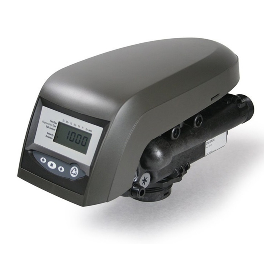
Installer Manual 255/LOGIX 742-762-764 - Description 3.3. Description and components location One-piece valve disc spring Injector and cap Optical sensor Control module mount Manifold connection LCD display BLFC/Refill controller Brine tank tube Check ball connection Air check Manual REGEN button UP button SET button DOWN button... -
Page 17: Options Available On The Valve
Installer Manual 255/LOGIX 742-762-764 - Description 3.4. Options available on the valve 3.4.1. Autotrol Logix residential/commercial series auxiliary microswitch kits The Logix residential/commercial series switch kits allow you to provide an electrical signal during the valve operation. The switches can be wired independently in N.O or NC. The switches are available for 0.1 Amp or 5 Amp rating. - Page 18 Installer Manual 255/LOGIX 742-762-764 - Description 3.4.1.2 Top plate mount The microswitch is located under the cover and is screwed to the top plate. The switch is turned on/ off by a cam lobe on the camshaft. Its function is to signal that the unit is in-service or out-of-service (regenerating).
-
Page 19: System Regeneration Cycle (8-Cycles Operation)
Installer Manual 255/LOGIX 742-762-764 - Description 3.5. System regeneration cycle (8-cycles operation) Service (downflow) — cycle C0 Untreated water is directed down through the resin bed and up through the riser tube. The hardness ions attach themselves to the resin and are removed from the raw water being exchanged on the resin beads towards sodium ions. - Page 20 Installer Manual 255/LOGIX 742-762-764 - Description SERVICE BACKWASH C1 and C6 Inlet Outlet Inlet Outlet Drain Valve Valve BRINE/SLOW RINSE REPRESSURIZE C2 and C3 Inlet Outlet Inlet Outlet Drain Valve Valve From brine tank FAST RINSE BRINE REFILL C5 and C7 Inlet Outlet Inlet...
-
Page 21: Regeneration Sequence For Twin And Lockout Systems
Installer Manual 255/LOGIX 742-762-764 - Description 3.6. Regeneration Sequence for Twin and Lockout Systems Note Perform a first regeneration for each tank, it will synchronize the camshafts if not already synchronized. Note When you fill water in the system, repeat operations described on chapter 7.1. Water filling, draining and watertightness inspection, page 58, for each tank. -
Page 22: Twin Parallel Systems
Installer Manual 255/LOGIX 742-762-764 - Description 3.6.2. Twin parallel systems Refill first option: off, Pr=0 Tank 1 and tank 2 are both in service position. Depending on the residual capacity, tank 1 or tank 2 will initiate first a regeneration. In this example tank 1 moves from service position to C1, then to C2, ... - Page 23 Installer Manual 255/LOGIX 742-762-764 - Description Refill first option: on, Pr=1 The refill first option has been designed mainly for twin parallel systems using only one brine tank. It allows a minimum time of 2 hours for brine to be saturated. Tank 1 and tank 2 are both in service position.
-
Page 24: Lockout "L" Systems
Installer Manual 255/LOGIX 742-762-764 - Description 3.6.3. Lockout "L" systems The first tank of the system whose capacity is exhausted will be regenerated first. The tank controller will send a signal to all others controllers in the system that will not be able to start a regeneration until it is finished. -
Page 25: System Sizing
Installer Manual 255/LOGIX 742-762-764 - System sizing System sizing 4.1. Recommendations 4.1.1. Injector/DLFC/Refill flow controler-Valve configuration Backwash flow Vessel diameter Media volume Injector Flow Refill flow control control [In] control [gpm] [gpm] 5/10 E [yellow] 0.33 F [peach] 0.33 G [tan] 0.33 H [lt purple] 0.33... -
Page 26: Injector Flow Rates
Installer Manual 255/LOGIX 742-762-764 - System sizing 4.3. Injector flow rates The following tables represent the injectors flow rate as a function of the inlet pressure for the different injector sizes. TOTAL BRINE DRAW RINSE Injector "F" (Peach) Injector "E" (Yellow) For 7"... - Page 27 Installer Manual 255/LOGIX 742-762-764 - System sizing TOTAL BRINE DRAW RINSE Injector "K" (Pink) Injector "J" (Light Blue) For 12" Tanks For 10" Tanks Inlet pressure [bar] Inlet pressure [bar] Injector "L" (Orange) For 13 " and 14" Tanks Inlet pressure [bar] Ref.
-
Page 28: Resin Exchange Capacity Upon Salt Dosage For Standard
Installer Manual 255/LOGIX 742-762-764 - System sizing 4.4. Resin exchange capacity upon salt dosage for standard efficiency Salt amount Corresponding resin exchange capacity grams / grams / °f.m °d.m liter of resin as CaCO liter of resin liter of resin liter of resin 29.9 2.99... -
Page 29: Resin Exchange Capacity Upon Salt Dosage For High Efficiency
Installer Manual 255/LOGIX 742-762-764 - System sizing 4.5. Resin exchange capacity upon salt dosage for high efficiency Salt amount Corresponding resin exchange capacity grams / grams / °f.m °d.m liter of resin as CaCO liter of resin liter of resin liter of resin 33.6 3.36... -
Page 30: Installation
Installer Manual 255/LOGIX 742-762-764 - Installation Installation 5.1. Safety notices for installation • Observe all warnings that appear in this manual; • only qualified and professional personnel are authorized to carry out installation work. 5.2. Installation environment 5.2.1. General • Use only brine salts designed for water softening. -
Page 31: Mechanical
Installer Manual 255/LOGIX 742-762-764 - Installation 5.2.3. Mechanical • Do not use petroleum-based lubricants such as vaseline, oils, or hydrocarbon-based lubricants. Use only 100% silicone lubricants; • all plastic connections should be hand tightened. PTFE (plumber’s tape) may be used on connections that do not use an O-ring seal. -
Page 32: Integration Constraints
Installer Manual 255/LOGIX 742-762-764 - Installation 5.3. Integration constraints Location of a water treatment system is important. The following conditions are required: • level platform or floor; • room to access equipment for maintenance and adding brine (salt) to tank; •... -
Page 33: Block Diagram And Configuration Example
Installer Manual 255/LOGIX 742-762-764 - Installation 5.4. Block diagram and configuration example 5.4.1. Simplex systems Pressure gauge Block Main inlet diagram User’s line Check valve to prevent water hammer and Filter cartridge eventual hot water returns. Pressure regulator By-pass Suggested options Meter Can be integrated in the valve Drain line... -
Page 34: Twin Parallel / Alternating Systems
Installer Manual 255/LOGIX 742-762-764 - Installation 5.4.2. Twin parallel / alternating systems Note For the description of the elements below, please refer to chapter 5.4.1. Simplex systems, page 33. Block diagram 1st valve 2nd valve system system Example of triplex parallel system installation Outlet Inlet... -
Page 35: Valve Connection To Piping
Installer Manual 255/LOGIX 742-762-764 - Installation 5.5. Valve connection to piping The connections should be hand tightened using PTFE (plumber’s tape) on the threads if using the threaded connection type. In case of heat welding (metal type connection), the connections should not be made to the valve when soldering. - Page 36 • In any case, any failure caused by improper installation and/or piping connections may void the warranty of Pentair products. • In the same way, using lubricant* on the valve thread is not allowed and will void the warranty for the valve and tank.
-
Page 37: Connections (Electrical)
Installer Manual 255/LOGIX 742-762-764 - Installation 5.6. Connections (electrical) Controller connections: Lockout connection / remote start dry contact signal input (764 only) Chlorine generator outlet (EU versions only) AC transformer input (low voltage) Main motor & optical sensor connection Sensor input for turbine 760/762/764 Remote start dry contact signal input 740/ Secondary valve motor and optical sensor connection (764 only) Simplex system with the possibility of triggering regeneration by external signal:... - Page 38 Installer Manual 255/LOGIX 742-762-764 - Installation Interconnected multi-simplex systems Lockout "L" (764L only): For each valve of the system the following connections must be made: the controller connection to an electrical outlet, the motor and optical sensor connections to the valve controller and the controller connections between each others via an interconnecting cable (3020228: remote start/lockout cable) (for a N valves system, it will require N-1 cables).
-
Page 39: Bypassing
Installer Manual 255/LOGIX 742-762-764 - Installation 5.7. Bypassing A bypass valve system should be installed on all water conditioning systems. Bypass valves isolate the softener from the water system and allow unconditioned water to be used. Service or routine maintenance procedures may also require that the system is bypassed. Normal operation In Bypass ... -
Page 40: Drain Line Connection
Installer Manual 255/LOGIX 742-762-764 - Installation 5.8. Drain line connection Note Standard commercial practices are expressed here. Local codes may require changes to the following suggestions. Check with local authorities before installing a system. The unit should not be more than 6.1 m from the drain. Use an appropriate adapter fitting to connect 12.7 mm plastic tubing to the drain line connection of the control valve. -
Page 41: Overflow Line Connection
Installer Manual 255/LOGIX 742-762-764 - Installation 5.9. Overflow line connection In the event of a malfunction, the brine tank overflow fitting will direct “overflow” to the drain instead of spilling on the floor. This fitting should be on the side of the cabinet or brine tank. Most tank manufacturers include a post for the tank overflow connector. -
Page 42: Brine Line Connection
Installer Manual 255/LOGIX 742-762-764 - Installation 5.10. Brine line connection The brine line from the tank connects to the valve. Make the connections and hand tighten. Be sure that the brine line is secure and free from air leaks. Even a small leak may cause the brine line to drain out, and the softener will not draw brine from the tank. -
Page 43: Programming
Installer Manual 255/LOGIX 742-762-764 - Programming Programming 6.1. Display 1. Hourglass Displayed when the motor is running. The camshaft should be turning. 2. Cursor These cursors appear next to the item that is currently displayed. 3. Days of the week Displayed days of the week. - Page 44 Installer Manual 255/LOGIX 742-762-764 - Programming 11. "g/L" Indicates that the value entered/displayed for salt amount is in grams/ Liter of resin. 12. "KG" Indicates that the value entered/displayed is in kilograms or kilograins. 13. "x100" x100 multiplier for large values. Indicates that the value entered/displayed for salt amount is in pounds 14.
-
Page 45: Commands
Installer Manual 255/LOGIX 742-762-764 - Programming 6.2. Commands - Down arrow Scrolls down or decrement through a group of choices. Accepts a setting that normally becomes stored in memory. - Set Also used together with the arrow buttons to access special features. - Up arrow Scrolls up or increment through a group of choices. -
Page 46: Basic Programming
Installer Manual 255/LOGIX 742-762-764 - Programming 6.3. Basic programming Note Menus are displayed in a defined and incremental order. 6.3.1. Basic programming 742 - 762 controller 6.3.1.1 Program valve type Set your valve type through the options. to scroll through valve type choices. →... - Page 47 Installer Manual 255/LOGIX 742-762-764 - Programming 6.3.1.5 Regeneration time Set the time when regeneration will take place. Press → Regeneration time flashes. Adjust displayed time with Default setting: 2:00am. Press to validate the selection and advance to the next parameter. 6.3.1.6 Days override (762 controller only) Set the number of days for calendar override.
- Page 48 Installer Manual 255/LOGIX 742-762-764 - Programming 6.3.1.9 Amount of salt used per regeneration Set desired salt amount in g/L. Press → Salt amount flashes. Adjust displayed salt amount with Press to validate the selection and advance to the next parameter. 6.3.1.10 Estimated system capacity Note...
-
Page 49: Basic Programming 764 Controller
Installer Manual 255/LOGIX 742-762-764 - Programming 6.3.2. Basic programming 764 controller 6.3.2.1 Program valve and system types Set your valve and system types through the options. to scroll through valve and system types choices. → Display flashes. Choose the 255 valve type and the corresponding system type. Press to validate and advance to the next parameter. - Page 50 Installer Manual 255/LOGIX 742-762-764 - Programming 6.3.2.3 Time setting Set the current time. Press → Time flashes. Adjust displayed time with Press to validate the selection and advance to the next parameter. 6.3.2.4 Day of week Set the current day of the week. Press →...
- Page 51 Installer Manual 255/LOGIX 742-762-764 - Programming 6.3.2.7 Amount of salt used per regeneration Set desired salt amount in g/L. Press → Salt amount flashes. Adjust displayed salt amount with Press to validate the selection and advance to the next parameter. 6.3.2.8 Estimated system capacity Note...
-
Page 52: Advanced Programming (8-Cycles Softener System)
Installer Manual 255/LOGIX 742-762-764 - Programming 6.4. Advanced programming (8-cycles softener system) Note Menus are displayed in a defined and incremental order. Note Press and hold for 5 seconds to access advance programming. A "P" symbol is displayed on the bottom left of screen. The 742/762/764 features an advanced programming level that allows the installing dealer to make changes to the controller for more demanding applications. - Page 53 Installer Manual 255/LOGIX 742-762-764 - Programming Default Units of Parameter description Range of values Notes value measure 0 = US unit. Units of measure 0 - 1 1 = Metric unit. 0 = 12 hour clock, flow rate displayed. 1 = 24 hour clock, flow rate displayed.
- Page 54 Installer Manual 255/LOGIX 742-762-764 - Programming Default Units of Parameter description Range of values Notes value measure 762/764 controllers only: 0 = internal turbine, Magnum IT NHWB. 1 = 1" Autotrol turbine, 2 turbines per system. 2 = 2" Autotrol turbine, 2 turbines per system.
-
Page 55: Cycle Time Programming
Installer Manual 255/LOGIX 742-762-764 - Programming 6.5. Cycle time programming Press and hold the for 5 seconds when the controller is not in regeneration to enter cycle time programming. → A small “C#” with a number will be displayed indicating the controller is in cycle time programming. -
Page 56: Diagnostic
Installer Manual 255/LOGIX 742-762-764 - Programming 6.6. Diagnostic Press and hold for 5 seconds, diagnostic H symbol is displayed on the bottom left of the screen. Diagnostic Description Unit Range Code Resin Initial setting value Litre Volume Days since last regeneration Days 0 - 255 Current flow rate... -
Page 57: Resetting The Controller
Installer Manual 255/LOGIX 742-762-764 - Programming 6.7. Resetting the controller Caution Resetting the controller will delete all information stored in its memory, except the time and day. This will require you to reprogram the controller completely from the initial power-up mode. -
Page 58: Commissioning
Installer Manual 255/LOGIX 742-762-764 - Commissioning Commissioning Note This chapter is available for standard regeneration types. Contact your supplier if the actual regeneration is not standard and if you need assistance. 7.1. Water filling, draining and watertightness inspection 7.1.1. System started Once you have performed the previous initial programming steps, you will need to activate the softener. - Page 59 Installer Manual 255/LOGIX 742-762-764 - Commissioning 5. Add water to the brine tank (initial fill) (softener only). → With a bucket or hose, add approximately 15 liters (4 gallons) of water to the brine tank. If the tank has a salt platform in the bottom of the tank, add water until the water level is approximately 25 mm (1") above the platform.
-
Page 60: Additional Tips
Installer Manual 255/LOGIX 742-762-764 - Commissioning 7. Draw water from the brine tank. → From the treated water position (cycle C0), advance the valve to the draw brine position. Press for 5 seconds. The controller will begin a manual regen, and advance the control valve to the cycle C1 (Backwash). -
Page 61: Sodium Or Calcium Hypochlorite
Installer Manual 255/LOGIX 742-762-764 - Commissioning 7.2.2. Sodium or calcium hypochlorite These materials are satisfactory for use with polystyrene resins, synthetic gel zeolite, greensand and bentonites. 5.25% Sodium hypochlorite If stronger solutions are used, such as those sold for commercial laundries, adjust the dosage accordingly. -
Page 62: Operation
Installer Manual 255/LOGIX 742-762-764 - Operation Operation During a regeneration: • A "C#" is displayed to show the current cycle; • total regen time remaining is displayed on screen; • you can press and hold to show current cycle time remaining. 8.1. -
Page 63: To Advance Regeneration Cycles
Installer Manual 255/LOGIX 742-762-764 - Operation Immediate double regeneration Press and hold to start the second regeneration immediately following the current regeneration. → A solid "x2" symbol will be displayed. 8.3. To advance regeneration cycles Simultaneously press to advance to the next cycle. →... -
Page 64: Parallel Systems
Installer Manual 255/LOGIX 742-762-764 - Operation 8.5.2. Parallel systems Parameter P16 is used to determine the method for demanded initiated regeneration. Four regeneration modes are possible: • P16 = 0, delayed regeneration with a variable reserve: Regenerations will start only at the time of regeneration entered in P3. A tank is regenerated if the remaining capacity in that tank is below the minimum required capacity needed to meet the next days calculated water usage requirement. - Page 65 Installer Manual 255/LOGIX 742-762-764 - Operation • P16 = 2, immediate regeneration - fixed reserve/delayed regeneration - variable reserve: This option uses the features of both options P16 = 0 and P16 = 3. This is the most versatile of regeneration options.
-
Page 66: Maintenance
Installer Manual 255/LOGIX 742-762-764 - Maintenance Maintenance Mandatory Cleaning and maintenance shall take place at regular intervals in order to guarantee the proper functioning of the complete system, and be documented in the Maintenance chapter in the User Guide document. Mandatory... -
Page 67: Regeneration Test
Installer Manual 255/LOGIX 742-762-764 - Maintenance 9.1.3. Regeneration test 1. Check condition of brine tank and any associated equipment. 2. Check salt level in brine tank. 3. Initiate regeneration test. → Check brine draw during brine draw stage, observe aircheck ball and make sure of proper function. - Page 68 Installer Manual 255/LOGIX 742-762-764 - Maintenance Items 1 year 2 year 3 year 4 year 5 year Motor, motor cable and Check Check Check Check Replace optical sensor harness Optical sensor Check Check Check Check Replace Inlet Hardness Check Check Check Check Check...
-
Page 69: Recommendations
Installer Manual 255/LOGIX 742-762-764 - Maintenance 9.3. Recommendations 9.3.1. Use original spare parts Caution To ensure correct operation and safety of the device, only use original spare parts and accessories recommended by the manufacturer. Parts to keep in stock for potential replacements are motor and optical sensor, controller, transformer, injectors, flapper kit, O-ring kit, refill and DLFC. -
Page 70: Cleaning The Injector
Installer Manual 255/LOGIX 742-762-764 - Maintenance 9.4.2. Cleaning the injector Operation Using a Torx key, unscrew and remove the injector cap (4). Caution Take care not to damage the injector (5). Using pliers, gently extract the injector (5) from valve body. Clean the injector (5) using compressed air, a soft brush or possibly a pin. -
Page 71: Cleaning The Injector Screen Cap
Installer Manual 255/LOGIX 742-762-764 - Maintenance 9.4.4. Cleaning the injector screen cap Operation Using a Torx key, unscrew and extract the injector screen cap (4). Unclip the white plastic basket (5) and clean it with a soft brush. Use of descaling agent such as white vinegar might be required in case of impurities on the plastic basket (5). -
Page 72: Cleaning The Air Check Valve
Installer Manual 255/LOGIX 742-762-764 - Maintenance 9.4.6. Cleaning the air check valve Operation Unscrew brine pipe (5). Using a Phillips screwdriver, loosen air check cap screw (2) (2x). Let the 2 screws (2) on the cap (4). Remove the cap (4). Clean the air check ball (3) and groove (1) using a soft cloth or a soft brush. -
Page 73: Disassembling Valve From Tank
Installer Manual 255/LOGIX 742-762-764 - Maintenance 9.4.7. Disassembling valve from tank Operation Tip Depending on the maintenance required, it may be useful to disassemble the valve from the tank in order to have easier access. Unlock the cover (1) from the slide clips (2) (one on each side of the valve). Lift the cover (1). -
Page 74: Motor And Camshaft Replacement
Installer Manual 255/LOGIX 742-762-764 - Maintenance 9.4.8. Motor and camshaft replacement Operation Remove the white locking pin (2) securing the motor (3). Turn the motor (3) counter clockwise and slide it out of its position. Slide the camshaft (1) backwards until it is released from its mounting boss, then lift it up. 74 / 92 Ref. -
Page 75: Optical Sensor And Controller Replacement
Installer Manual 255/LOGIX 742-762-764 - Maintenance 9.4.9. Optical sensor and controller replacement Operation Note To remove the optical sensor, you first have to disassemble the camshaft. See “Motor and camshaft replacement”, page 74. Caution Take care with sharp edges. The optical sensor (2) is clipped on the front edge, gently press on the clips to release the optical sensor (2) from its location. -
Page 76: Top Plate And Disc Valve Replacement
Installer Manual 255/LOGIX 742-762-764 - Maintenance 9.4.10. Top plate and disc valve replacement Operation Caution Take care with sharp edges. Use of protective glove is highly recommended to remove the spring (3). Using a flat screwdriver, release the flapper springs (2) one by one and then remove the spring (3). -
Page 77: Valve On Tank Assembly
Installer Manual 255/LOGIX 742-762-764 - Maintenance 9.4.11. Valve on tank assembly Operation Lubricate the seals with approved silicone grease. Spin the valve (1) onto the tank (2), ensuring the threads are not cross-threaded. Rotate the valve (1) clockwise and freely, without using force until it comes to a stop. Note... -
Page 78: Troubleshooting
Installer Manual 255/LOGIX 742-762-764 - Troubleshooting Troubleshooting Err. code Cause Reset and recovery Controller power has been connected Reset controller. ERR 1 and the controller is not sure of the See 6.7. Resetting the controller, operating status. page 57. Disconnect and reconnect the power. Controller power does not match 50 or If problem is not solved, obtain an ERR 2... - Page 79 Installer Manual 255/LOGIX 742-762-764 - Troubleshooting Err. code Cause Reset and recovery Controller on tank 2 does not know the Wait for two minutes, the controller position of the camshaft. will return to home position. The Camshaft should be rotating to find hourglass should be flashing on the Home position.
- Page 80 Installer Manual 255/LOGIX 742-762-764 - Troubleshooting Issue Cause Reset and recovery Control brine dosage setting and Improper regeneration. repeat regeneration. Hard water Leaking of external bypass valve. Replace bypass valve. leakage after O-ring around riser pipe damaged. Replace O-ring. regeneration. Verify appropriate brine amount and Incorrect capacity.
- Page 81 Installer Manual 255/LOGIX 742-762-764 - Troubleshooting Issue Cause Reset and recovery No brine in brine tank. Add brine to brine tank. No conditioned Injector plugged. Clean injector and screen. water after Put controller momentarily into brine regeneration. Air check valve closes prematurely. cycle (C2).
-
Page 82: Spare Parts
Installer Manual 255/LOGIX 742-762-764 - Spare parts Spare parts 11.1. Valve parts list 82 / 92 Ref. MKT-IM-021 / A - 20.02.2019... - Page 83 Installer Manual 255/LOGIX 742-762-764 - Spare parts Assembly Item Part number Description quantity 1244650 255 valve assy with out flow controls 1033784 255 tank adapter new style 1010154 O-Ring EP, tank 1232370 O-Ring EP, riser tube 1235340 Top plate, 255 valve, 700/860 series 1235341 Spring, one-piece, 255 valve 1236246...
- Page 84 Installer Manual 255/LOGIX 742-762-764 - Spare parts Assembly Item Part number Description quantity 1000212 Drain control assy with o-ring No.10 (2.5 gpm; 9.5 Lpm) 1000213 Drain control assy with o-ring No.12 (3.5 gpm; 13.2 Lpm) Drain control assy with o-ring No.13 (4.1 gpm; 15.5 Lpm) no 1000214 ball Drain control assy with o-ring No.14 (4.8 gpm;...
-
Page 85: Options And Special Kits
Installer Manual 255/LOGIX 742-762-764 - Spare parts 11.2. Options and special kits 742/762/764 Controllers Assembly Item Part number Description quantity Logix 742 controller - picto 1242159 Softening, check salt diode visible Logix 742 controller - Picto 1242151 Softening, check salt diode not visible Logix 762 controller - Picto 1265830 Softening, check salt diode visible... - Page 86 Installer Manual 255/LOGIX 742-762-764 - Spare parts Meter adapter Assembly Item Part number Description quantity 1032350 Meter adapter kit 1040524 Piping boss/meter install kit 86 / 92 Ref. MKT-IM-021 / A - 20.02.2019...
- Page 87 Installer Manual 255/LOGIX 742-762-764 - Spare parts Piping boss (manifold) Assembly Item Part number Description quantity 3023761 Piping boss 3/4" BSPT s. steel S 3/8" BSPT drain 3023747 Piping boss 1" BSPT s. steel 1/2" BSPT drain 1040283 Piping boss 3/4" BSPT Noryl 1/2" BSPT drain 1040524 Piping boss/meter install kit 3028275...
- Page 88 Installer Manual 255/LOGIX 742-762-764 - Spare parts Bypass & connections Assembly Item Part number Description quantity 1040769 Bypass body assy (includes bypass installation kit) 1040524 Bypass installation kit 1034302 Bypass repair kit (rotor seals & clips) 3028264 Drain elbow for bypass 256 3023824 3/4"...
- Page 89 Installer Manual 255/LOGIX 742-762-764 - Spare parts Interconnecting kit & connections Assembly Item Part number Description quantity Deluxe interconnecting kit 255 twin DN25 mm female 32 mm. Includes: 3019931-2532 - 2x bypass 256 (1040769); - 1x interconnecting piping elements; - 2x 32 mm PVC tube adapter kit (1001615) 1040769 Bypass body assembly (includes bypass installation kit) 1034302...
- Page 90 Installer Manual 255/LOGIX 742-762-764 - Spare parts Valve installation kits Assembly Item Part number Description quantity Installation kit-255. 3029815 Consists of E01240; 1009116; 3028263; 3020267; CC-D1203; MS-RI3460; AV090 E01240 Air check elbow (CA40) 1/4" FNPT- 3/8" T 1009116 Upper screen 3028263 Riser tube 1.050"...
-
Page 91: Disposal
This will help to reduce the impact on the environment, health, safety and help to promote recycling. Pentair does not collect used product for recycling. Contact your local recycling center for more information. - Page 92 www.pentairaquaeurope.com...