
Related Manuals for Comelit 6701W


Summary of Contents for Comelit 6701W
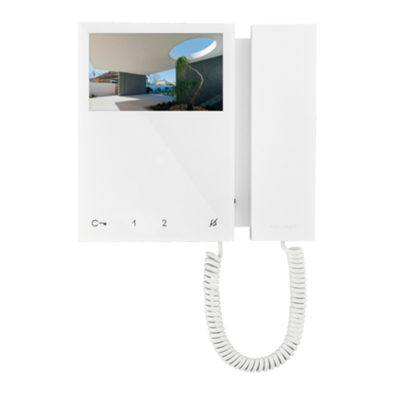
- Page 1 TECHNICAL MANUAL Mini door entry monitor with handset Passion.Technology.Design. Art. 6701W, 6701W/BM, 6701W/8...
-
Page 2: Table Of Contents
Installation All activities connected to the installation of Comelit products must be carried out by qualified technical personnel, with careful observation of the indications provided in the Manuals / Instruction sheets supplied with those products. -
Page 3: Door Entry Monitor Description
Equipped as standard with 4 soft touch buttons (8 with 6701W/8) for controlling lock-release, self activation, switchboard call and Privacy function, as well as door status indicator LEDs. Manages floor door calls as standard. Complete with 2 x 8-position dip- switches for programming the user code and button programming. -
Page 4: Legend: Buttons And Indicator Leds
(*) Buttons may be programmed as: • AUTOMATIC LOCK-RELEASE ON RECEIPT OF CALL (Doctor) See paragraph “Pressing and holding keys (disabled by default from firmware version 3.0.1 (3.2.0 for 6701W/8)” • INTERCOM Allows a call from one internal unit to one or more internal units •... -
Page 5: Technical Specifications
Technical specifications 6701W 6701W/BM 6701W/8 GENERAL DATA Height (mm) Width (mm) Depth (mm) Weight: (g) Material Colour White RAL9003 White RAL9003 White RAL9003 Surface mounting Desk base mounting LCD SPECIFICATIONS Size (inches) 4.3” 4.3” 4.3” Aspect ratio 16:9 16:9 16:9... -
Page 6: Installation
Installation 17,5 cm optional fixing CLACK! CLACK! CLACK! -
Page 7: Removing/Fitting The Terminal
Removing/Fitting the Terminal Connections 6701W 6701W/BM 6701W/8 VIDEO ENTRY SYSTEM RISER 1214/2C FLOOR DOOR CALL VIDEO ENTRY SYSTEM RISER 20 m MAX - Use shielded cable for the connection and do not route the cables in the vicinity of heavy inductive loads or power supply cables (230V / 400V). -
Page 8: Settings
Settings Main and secondary door entry monitors In systems with power supply unit 1209, 1210 or 1210A, you can configure a maximum of 1 main door entry monitor, while in systems with power supply unit 4888C you can configure up to 2 main door entry monitors. To configure the door entry monitor as main, set S2di DIP 8 to OFF To configure the door entry monitor as secondary, set S2 DIP 8 to ON 1 2 3 4... -
Page 9: Button Configuration
(B-P) suggested in the table. All the buttons will change function. Basic configuration Mini 6701W/8 S2 Dip-switches Mini 6701W - Mini 6701W/BM DIP 1 DIP 2 DIP 3 DIP 4... -
Page 10: Advanced Configuration
Advanced configuration If the standard configuration settings (A-P) do not reflect requirements, the buttons can be programmed differently by carrying out the steps below. After programming, set S2 DIP-switches 1-2-3-4 (PROG) to ON. With these DIP-switch settings, the buttons manage the programmed functions. -
Page 11: Selective Intercom Address
Selective intercom address TABLE B Code S1 DIP-switch ON Code S1 DIP-switch ON Code S1 DIP-switch ON Assigning selective address (Steps only need to be carried out for “Intercom call to selective address” programming) Take note of the S1: Set an address. S2: Set the DIP-switches as S1, S2 settings and (“TABLE... -
Page 12: Coded Actuator: Button Programming
Coded actuator: button programming 1. Take note of the S1 DIP-switch settings. 2. Exit programming mode by setting S2 DIP 6 to OFF. » the LED flashes Refer to the table to identify a DIP-switch combination in which the actuator function (ACT) “Basic configuration”... -
Page 13: Changing The Ringtone
Changing the ringtone 1. Press and hold for 6 sec. » a confirmation tone is emitted » the LED flashes √ the procedure can only take place while the system is in standby; otherwise the LED will flash 4 times to inform the user that the system is busy 2. -
Page 14: Addressing Table
Addressing table DIP-switch Code 1,2,3,4,5 1,3,4,5,6 1,2,4,5,7 1,4,5,6,7 1,2,3,5,8 1,3,5,6,8 1,2,5,7,8 2,3,4,5,6 3,4,5,7 2,4,5,6,7 4,5,8 2,3,5,6,8 3,5,7,8 1,2,3,4,5.6 1,3,4,5,7 1,2,4,5,6.7 1,4,5,8 1,2,3,5,6.8 1,3,5,7,8 2,3,4,5,7 3,4,5,6,7 2,4,5,8 4,5,6,8 2,3,5,7,8 1,2,6 1,2,3,4,5.7 1,3,4,5,6.7 1,2,4,5,8 1,4,5,6,8 1,2,3,5,7.8 2,3,4,5,6.7 3,4,5,8 2,4,5,6,8 4,5,7,8 1,2,3 1,3,6 1,2,7 1,6,7 1,2,3,4,5,6,7... - Page 15 C E R T I F I E D M A N A G E M E N T S Y S T E M S w w w . c o m e l i t g r o u p . c o m Via Don Arrigoni, 5 - 24020 Rovetta (BG) - Italy...