KaVo ORTHOPANTOMOGRAPH OP 3D Service Manual
Hide thumbs
Also See for ORTHOPANTOMOGRAPH OP 3D:
- User and installation manual (221 pages) ,
- User manual (109 pages) ,
- Installation manual (40 pages)
Table of Contents
Advertisement
Quick Links
Advertisement
Table of Contents

Related Manuals for KaVo ORTHOPANTOMOGRAPH OP 3D


Summary of Contents for KaVo ORTHOPANTOMOGRAPH OP 3D
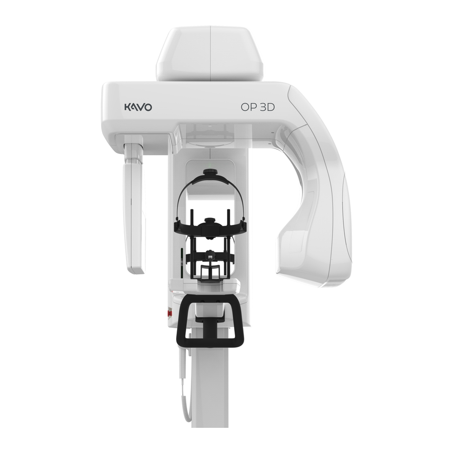
- Page 1 ORTHOPANTOMOGRAPH ™ OP 3D Service manual ENGLISH 215241 rev. 4 0.805.4918...
-
Page 3: Table Of Contents
Contents 1 Disclaimer..............6 2 Introduction..............7 ™ 2.1 ORTHOPANTOMOGRAPH OP 3D............. 7 2.2 Intended use..................7 2.3 Abbreviations..................7 2.4 Disposal and recycling................8 2.5 Associated documentation............... 8 3 Safety................9 3.1 Service precautions and warnings.............9 3.1.1 Signal words................9 3.1.2 General servicing precautions............9 3.1.3 Electrical safety................ - Page 4 5 Diagrams..............45 5.1 Wiring diagram..................45 5.2 Fusing diagram..................47 5.3 Emergency stop..................47 5.4 Mains voltage distribution..............47 5.5 Power distribution +24Vdc..............48 5.6 Ethernet communication................ 48 5.7 CAN communication................48 5.8 i2C self diagnosis communication............49 5.9 Rotation movement................49 5.10 Linear movement................50 5.11 Pivot movement..................50 5.12 Z movement..................
- Page 5 8.3.6 Replacing the main cable set.............125 8.3.7 Replacing the i2000 image capture board........128 8.3.8 Replacing the i3000 main control board........129 8.3.9 Replacing the tube head............130 8.3.10 Replacing the lower shelf upper cover assembly......134 8.3.11 Replacing the collimator............137 8.3.12 Removing the upper shelf plate..........140 8.3.13 Replacing the linear and pivot movement and motor....
-
Page 6: Disclaimer
™ ORTHOfocus and Low Dose Technology are either registered trademarks or trademarks of KaVo Kerr Group Finland in the United States and/or other countries. ™ KaVo is either registered trademark or trademark of Kaltenbach & Voigt GmbH in the United States and/or other countries. -
Page 7: Introduction
2 Introduction 2 Introduction ™ 2.1 ORTHOPANTOMOGRAPH OP 3D ™ The ORTHOPANTOMOGRAPH OP 3D (later called device) is a dental X-ray device producing high quality digital images of dentition, TM-joints and skull. To take images, you need a suitable workstation connected to the device and a dental imaging software to capture and manage the images. -
Page 8: Disposal And Recycling
2 Introduction 2.4 Disposal and recycling The device and its components are lead-free, including its radiation protection components. The device meets the RoHS Directive 2011/65/EU, WITHOUT any exemptions mentioned in Annex IV. At least the following parts of the device should be re-cycled according to local and national regulations regarding disposal of non-environmentally friendly materials: •... -
Page 9: Safety
3 Safety 3 Safety 3.1 Service precautions and warnings 3.1.1 Signal words The following signal words and labels are used in this document: WARNING! Indicates a hazardous situation which, if not avoided, could result in death or serious injury. CAUTION! Indicates a hazardous situation which, if not avoided, could result in minor or moderate injury. -
Page 10: Electrostatic Discharge
3 Safety Do not compromise: • EMI enclosures and tightness of cases and screw contacts • Gaskets • Cable shields and their grounding to the chassis • Electromagnetic immunity by incorrect cabling. 3.1.4 Electrostatic discharge Electrostatic Discharge (ESD) can damage or destroy electronic components. When you service the device take precautions to avoid electrostatic charge to build up and discharge (ESD). -
Page 11: Symbols That May Appear On The Device Or Its Parts
3 Safety Before you use or service the device familiarize yourself with local and national radiation safety standards and requirements relating to dental x-ray equipment. 3.1.7 Symbols that may appear on the device or its parts Manufacturer Date of manufacture Serial number Catalog or model number Caution... - Page 12 3 Safety Operating instructions Refer to operating instructions for more information. The operating instructions can be supplied electronically or in paper format. Caution: Federal law restricts this device to sale by or on the order of a licensed healthcare practitioner. This symbol indicates that the waste of electrical and electronic equipment must not be disposed as unsorted municipal waste and must be collected separately.
-
Page 13: Device Description
4 Device description 4 Device description 4.1 Mechanical description 4.1.1 Main parts 1. Column 2. Carriage 3. Upper shelf 4. Rotating unit 5. Sensor 6. Tubehead 7. Power switch (Back of the device) 8. Exposure switch 9. Positioning panel 10. Emergency stop switch 11. -
Page 14: Device Movements
4 Device description 4.1.2 Device movements Z - Column UP/DOWN movement P - Pivot movement of the upper shelf L - Linear movement of the rotating unit R - Rotating movement of the rotating unit CV - Vertical movement of the collimator plate CH - Horizontal movement of the collimator plate... -
Page 15: Status Indicator Light
4 Device description Rotating unit covers Rotator back cover Rotator front cover Rotator finger protection upper Rotator finger protection lower Tube head front cover Tube head back cover Tube head plate 3D sensor back cover 3D sensor front cover Outer sensor collar cover Inner sensor collar cover Lower shelf covers Lower shelf cover set with... -
Page 16: Device Labels
4 Device description 4.1.5 Device labels 1. Type label 2. Sensor label 3. THA label 4. Collimator label 5. Filtration label 6. Warning label 4.1.6 Emergency stop switch An emergency stop switch is located on the left side of the carriage. Pressing the emergency stop switch immediately terminates the imaging and all device movements and resets all circuit boards. -
Page 17: Device Software
4 Device description 4.2 Device software 4.2.1 Firmware overview Firmware description The device firmware (FW) consists of board and processor component specific binary files, that are loaded on various system board locations. NOTICE! The device Firmware versions can be found under the System info on the Settings menu on the GUI. - Page 18 4 Device description 6. Enter PIN code 1917 to access the Service menu. 7. Browse to Service> FW Update. 8. Click Select File and browse to the location to the firmware file to be loaded, for example C:\temp\OP_3D_EMBEDDED_SOFTWARE_Rx_y_z_abcd.tar.gz. Select the update file.
-
Page 19: Electrical Description
4 Device description 4.3 Electrical description 4.3.1 Circuit board locations 1. i4000 Power Supply board 2. i2000 Image Capture Board 3. i3000 Main Control Board 4. i4100 Back panel board 5. i5000 Cascade board (in the Tubehead assembly) 6. i6000 User interface board 7. -
Page 20: Position Control
4 Device description For further information on the boards, see the relevant sections in this document. 4.3.3 Position control Positioning of the device is done by stepper- and DC-motors, using feedback from optical, resistive and Hall sensors. The control chain per actuator is described below. Upper shelf linear and pivot movement, rotator movement The movement is driven by a stepper motor. -
Page 21: Fuses
4 Device description Refer to User and Installation manual, chapter Mains power configuration for detailed instructions. NOTICE! In i4100 back panel board there is a switch (SW1) that is used for changing, for example, from permanent to plug connection. Refer to User and Installation manua, chapter Mains power configuration. -
Page 22: User Interfaces
4 Device description 4.4 User Interfaces 4.4.1 Graphical User Interface (GUI) GUI Overview 1. Selected patient name and Patient Identification (ID). 2. Selection of imaging modality, PAN or 3D. 3. Imaging program settings. 4. Main view area. Shows a dental chart for the selected modality and previews of the taken images. - Page 23 4 Device description IMAGING PROGRAM SETTINGS: Test mode Indicates if Test mode is active. Press Test mode icon to disable/enable device radiation production. This mode can be used for example to demonstrate the device movements. You can also use the positioning panel to activate the Test mode. Patient size Indicates the currently selected patient size preset.
- Page 24 4 Device description Settings menu 1. QUALITY CONTROL Shows a list of Quality Control (QC) programs, their completion status and last completion date. ™ ORTHOPANTOMOGRAPH OP 3D...
- Page 25 4 Device description 2. CALIBRATIONS Shows a list of user performable device calibrations, their completion status and last completion date. The calibrations are performed through this menu. 3. SYSTEM INFO Software Show the device serial number and firmware versions. versions Notices Legal information and terms and conditions for use.
- Page 26 4 Device description 4. PREFERENCES Configurations Friendly name Set a name for the device, which is shown next to the settings icon and on the imaging software. 3D Metal Artefact Enable or disable MAR, Metal Artefact Reduction Reduction. MAR is used to reduce the effect of metals and other dense radiopaque objects on the 3D image.
- Page 27 4 Device description Patient size Adjust the default mA and kV values for imaging programs. configuration 5. SERVICE MENU NOTICE! This menu is intended for authorized service personnel only. The Service menu can be accessed only with a PIN code. The Service menu contains: •...
- Page 28 4 Device description Service menu NOTICE! The Service menu is intended only for authorized service men for service use. To access the Service menu from the Settings, input PIN code 1917 to the field: NOTICE! PIN code 0612 is intended for installation only and contents of the Service menu is limited.
- Page 29 4 Device description Service In the Service menu you can: • update the device firmware • perform accelerated motion test for different main movents • test the door and mirror door switch status change • drive the device to packing position •...
- Page 30 4 Device description Calibrations In the Calibrations menu you can select the device calibrations that you want to perform. For information on how to perform the calibrations, see User and Installation manual. Preferences In the Preferences> Configurations you can: • enter a friendly name (for the device) •...
- Page 31 4 Device description Refer to User and Installation manual, chapter Device configuration for instructions on setting and using the Preferences menu items. In the Preferences > Patient Size Configuration you can: • adjust the medium size patient values Verification The device offers Panoramic and 3D verification test programs with the device movements disabled.
- Page 32 4 Device description 5. Select the PAN testing tab for Panoramic verification test or 3D testing tab for 3D verification test. 6. Adjust the verification test settings: PAN testing • Select the mA and kV values for the test program using the + and - buttons. 7.
-
Page 33: Positioning Panel
4 Device description 12. If the verification fails, ensure the alignment of the measurement device and redo the test program. If the problem persists, contact service. 13. Adjust the verification test settings: 3D testing • Select the length of the radiation pulse, 5ms (LDT/standard), 10ms (Standard resolution) or Constant (High/ENDO resolution). -
Page 34: Circuit Boards
4 Device description 4.5 Circuit boards 4.5.1 i2000 image capture board The i2000 image capture board is located on top of the rotating unit, see Locations of circuit boards. The i2000 board handles image capturing function of the OP 3D X-ray imaging system. The main functions of the i2000 board are listed below. - Page 35 4 Device description Table 2: Indicators LED # Color Default Function Notes state Green Configuration done Green Ethernet Link Green FPGA init done Green Blinking Ethernet RX/TX activity Green P1V35 PG OFF when device is in the sleep mode FPGA PIO LED5 Green PAN_P5V_D_3D ON when 3D...
- Page 36 4 Device description LED # Color Default Function Notes state Motor driver POR on ON when a motor malfunction detected Green DDR_VTT OFF when device is in the sleep mode Green Blinking MCU STAT0 MCU SW controlled Green NSTATUS FPGA RESET Green CPAN_P12V ON when PAN...
-
Page 37: I3000 Main Control Board
4 Device description i2000 fuses Location Value Type Replaceable i2000 FUSE slow 4A Cooper Bussmann 250Vac 5x20 mm S506-4-R i2000 FUSE slow 6.3A Cooper Bussmann 250Vac 5x20mm S506-6.3-R i2000 Resettable Fuse Cooper Bussmann PPTC 16V, 0.25A, PTS120616V025 Itrip 0.5A Replacing the i2000 image board To replace the board, follow the instructions given in chapter Replacing the i2000 image capture... - Page 38 4 Device description Indicators LED # Color Default state Function Notes Green VAUX33 power on Green MWS Ethernet link Green i2000 Ethernet link Green ON/blink MWS Ethernet RX/TX activity Green Motor in reset (POR) Green +24V supply connected to board and FUSE ok Green ON/blink...
- Page 39 4 Device description i3000 fuses Location Value Type Replaceable i3000 6,3AT/250Vac Cooper Bussmann S506-6.3-R i3000 4A 250Vac slow (5x20mm) Cooper Bussmann S506-4-R i3000 1,1A/6V Resetable PTC#fuse i3000 1,1A/6V Resetable PTC#fuse i3000 0,25A/16V Resetable PPTC#fuse i3000 2A/6V Resetable PTC#fuse i3000 0,25A/16V Resetable PPTC#fuse i3000 0,25A/16V...
-
Page 40: I4000 Power Supply Board
4 Device description 4.5.3 i4000 power supply board The i4000 power supply board is located on the carriage. See figure Locations of circuit boards. The i4000 board is one of three control boards of the OP 3D X-ray imaging system. The main features of the i4000 power supply board are listed below. - Page 41 4 Device description i4000 fuses Location Value Type Replaceable i4000 FF8A/500Vac (6,3x32mm) Siba 70-125-40 8A i4000 2A/6V Resetable PPTC fuse Littelfuse 0805L200SLTHYR i4000 8AT/250Vac (5x20mm) Cooper Bussmann S506-8-R i4000 0.5A/6V Resetable PTC# F6-9 fuse Bourns MF- PSMF050X i4000 0.25A/16V Resetable PPTC#fuse No i4000 0.5A/6V Resetable PTC#fuse...
-
Page 42: I4100 Back Panel Board
4 Device description 4.5.4 i4100 back panel board The i4100 back panel board is located on the backside of the carriage. See Locations of circuit boards. The board has a mains input connector and mains fuses. It also has several connectors to external features. The main features of the i4100 back panel board are listed below. - Page 43 4 Device description The i8000 board generates exposure warning, ready and error status indications. The status is indicated with colored LEDs. Indicators Refer to Status indicator light for the indicators. Replacing the i8000 circuit board For instructions on how to replace the i8000 LED indicator board, see chapter Replacing the i8000 LED indicator board.
-
Page 44: I9000 Chin Rest Sensor Board
4 Device description 4.5.7 i9000 chin rest sensor board The i9000 chin rest sensor board is located in the lower shelf. See figure Locations of circuit boards. Functionality The i9000 board senses the chin rest positions and calibration phantoms with three HALL sensors. -
Page 45: Diagrams
5 Diagrams 5 Diagrams 5.1 Wiring diagram ™ ORTHOPANTOMOGRAPH OP 3D... - Page 46 5 Diagrams ABS. ROT. HOME ANGLE J1107 J1106 ROTATING J1012 J1027 J1013 J2003 J2002 J2001 J2010 J2000 J2011 J2004 J1031 CUB HOME SELF J7000 J7002 DIAGNOSTICS COL UPPER J1034 BORDER i2000 IMAGE CAPTURE BOARD i7000 TUBEHEAD INTERFACE BOARD J7005 J1032 J7001 J7003 J2015...
-
Page 47: Fusing Diagram
5 Diagrams 5.2 Fusing diagram i4000 POWER SUPPLY i2000 IMAGE CAPTURE Motors Motors GENERATOR i4100 BACK PANEL BOARD Logic DC/DC MAINS INLET i3000 MAIN CONTROL SUPPLY SWITCH Motors STAND-BY SUPPLY Logic 5.3 Emergency stop Emergency stop button J1011 i4000 5.4 Mains voltage distribution MAINS SWITCH 1A 2A J4107... -
Page 48: Power Distribution +24Vdc
5 Diagrams 5.5 Power distribution +24Vdc i2000 P24V 24V power supply i3000 J3002 J3003 P24V_MOT i4100 i4000 P24V_MOT P24V ON P24V J2000 J4101 J4013 J4020 P24V P24V P24V_MOT ON P24V ON P24V ON P24V MOTOR ON J4016 J4019 J1005 J7000 5.6 Ethernet communication Back panel Link... -
Page 49: I2C Self Diagnosis Communication
5 Diagrams 5.8 i2C self diagnosis communication +5Vdc i7000 6 12 5 +24Vdc J4019 +5Vdc +5Vdc +5Vdc +5Vdc i4000 i2000 i3000 +5V ON 5.9 Rotation movement MOTOR ERROR CAN BUS FROM J1012 i3000 i2000 2ph Step J2001 ROT. HOME J1027 ROT. -
Page 50: Linear Movement
5 Diagrams 5.10 Linear movement CAN BUS FROM J1015 i4000 i3000 2ph Step J3004 LINEAR HOME J1025 LINEAR ABS. J1017 5.11 Pivot movement CAN BUS FROM J1016 i4000 i3000 2ph Step J3005 PIVOT HOME J1026 PIVOT ABS. J1018 ™ ORTHOPANTOMOGRAPH OP 3D... -
Page 51: Z Movement
5 Diagrams 5.12 Z movement Z-ACTUATOR J1037 CAN BUS From i3000 i4000 UI PANEL J1011 TACOMETER i6000 Z-HOME J1039 5.13 Collimator movements ™ ORTHOPANTOMOGRAPH OP 3D... -
Page 52: Positioning Lights
5 Diagrams 5.14 Positioning lights LASER LIFT LASER HOME 2ph Step J1022 3D FOV J4018 HEIGHT CAN BUS J1008 FROM J1009 i3000 POSTERIOR ANTERIOR i4000 SHARP LAYER J1003 J1010 SAGITTAL 5.15 Imaging chain 3D Back J2013- 3:GND (trigger) panel - 4: Ext.trigger - 7: +12Vdc - 8: GND (PWR) 3D X-ray... -
Page 53: Exposure Control 1
5 Diagrams 5.16 Exposure control 1 J1005 J4019 J7000 THA PAN i7000 J4005 J7002 J1004 i4000 J4016 J7000 THA CEPH i7000 J4004 J7002 5.17 Exposure control 2 Exposure button J4103 J4101 J4013 Remote exposure i4000 P3V3 button J4014 i4100 Remote exposure button J4102 Door switch... -
Page 54: Exposure Warning Light
5 Diagrams 5.18 Exposure warning light Remote controller Exposure warning J4013 J4101 J4104/ i4100 J4102 J4105 i4000 External warning lamp J4007 J6001 i6000 Exposure warning Ready Error J4022 J8000 i8000 Exposure warning Ready Error 5.19 Device control panel Positioning panel FROM i4000 i6000... -
Page 55: Chin Rest Detection
5 Diagrams 5.20 Chin rest detection HAL-B HAL-A HAL-C FROM i3000 i4000 i9000 ™ ORTHOPANTOMOGRAPH OP 3D... -
Page 56: Maintenance
6 Maintenance 6 Maintenance The maintenance and calibration procedure intervals described here are minimum requirements and can be made more frequent and stringent to comply with local regulations regarding the use and maintenance of dental X-ray devices. 6.1 Annual maintenance Annual maintenance procedures must be performed annually to ensure that the performance and functionality of the device remains consistent. -
Page 57: Device Movements And Functionality
6 Maintenance 3. Visually check that the Ethernet cable is in good condition and not damaged in any way. 4. Visually check that the Remote exposure switch cable, Remote warning light cable and door switch cable, if installed, are in good condition and not damaged in any way. -
Page 58: Exposure Indicator Functionality
6 Maintenance 11. Select Pan and 3D imaging modalities from the device GUI and press the Patient positioning lights button. Check that the correct lights are lit according to the selected modality. For more information on the positioning lights, see the User and Installation Manual. -
Page 59: Changing The Fuses
6 Maintenance 7. When the exposure starts, check that all exposure warning indicators are working: • Exposure warning indicator on the GUI • Yellow exposure indicator light on the Positioning panel • Yellow exposure indicator light on the Status indicator light on top of the carriage. •... -
Page 60: Calibrations
6 Maintenance If you are using the Display Calibration Kit purchaceable from PaloDEx Group Oy, refer to the Display Calibration Kit Instructions. 6.2 Calibrations 6.2.1 When to calibrate the device The device must be calibrated and, if necessary, adjusted at regular intervals in accordance with the national regulations regarding the use, maintenance and service of dental X-ray devices. - Page 61 6 Maintenance Table 4: Calibration matrix i2000i3000 i4000 i3000 CollimatorTube Pivot Lasers Any head Panel part card linear in the sensors imaging chain Device Movement Calibration Movement Limits X-ray generator Calibration 3D Pixel Calibration Device Geometry Calibration Collimator Calibration PAN Pixel Calibration Geometry Calibration,...
-
Page 62: Troubleshooting
7 Troubleshooting 7 Troubleshooting Problem Possible cause Solution Taken image is not Local network connection The device stores the latest transferred to the modality is disrupted, which causes image until a confirmation workstation. loss of data. of a succesfull transfer to the workstation has been received. -
Page 63: List Of Error Codes
7 Troubleshooting will erase any image that is stored in the unit memory and this retrievable image will be lost. 7.2 List of error codes How to read the error codes table: • Have the OP 3D wiring diagram available and refer to it. NOTICE! Follow the troubleshooting procedures in the List of error codes. - Page 64 7 Troubleshooting Error code Problem Solution E00002 Invalid error code, you should Software error. Take logs and boot the not receive this. device. E08402 Emergency button active 1. Check that emergency button is not pressed. 2. Check connections: J4002, J1011, Emergency button If fail =>...
- Page 65 7 Troubleshooting Error code Problem Solution If same fail occurs => replace i4000 3. Replace the column. E09004 Fan failing 1. Check that there are no obstacles/ dirt in the fan. If fail => remove obstacles/dirt 2. Check connections: * J4023, FAN If fail =>...
- Page 66 7 Troubleshooting Error code Problem Solution E09008 UI panel missing 1. Check connections: * J4007, J6001 If fail (open) => replace user interface cable 2. Replace i6000 3. Replace i4000. E09009 Z motor opto missing 1. Check connections: * J4002, J1011, J1039 If fail (open) =>...
- Page 67 7 Troubleshooting Error code Problem Solution E09014 Coll up opto missing 1. Check connections: * J2005, J1034 If fail (open) => replace collimator motors optos cable * J1034, J1031 If fail (open) => replace collimator 2. Replace i2000. E09015 Coll right opto missing 1.
- Page 68 7 Troubleshooting Error code Problem Solution If fail (open) => replace linear sensor cable 3. Replace the resistive position sensor 4. Replace i3000. E09019 Resistive sensor rotator missing 1. Check that the wiper is pressing mechanically onto the surface of an resistive angle sensor.
- Page 69 7 Troubleshooting Error code Problem Solution * J2002, J1012 If fail (open) => replace rotating high torq mot cable 2.2 Replace motor 2.3 Replace i2000 3 For sensor swap: 3.1 Check connections: * J2003, J1014 If fail (open) => Replace detector swap cable 3.2 Replace motor 3.3 Replace i2000...
- Page 70 7 Troubleshooting Error code Problem Solution If the fuse blows again => replace i3000. 2.2 Replace i3000 E09026 Sensor current too high 1. Remove power supply connection J2013 from i2000 1.1 Check H9 and H10 LED on i2000 board during preparation (should be green) If fail then =>...
- Page 71 7 Troubleshooting Error code Problem Solution 2. Check connections: J4019, J1005, J7000 (pan-THA) 3. Re-run THA calibrations 4. Replace i4000 5. Re-run THA calibrations 6. Replace pan THA 7. Re-run THA calibrations 8. Replace main cable and twister cable assembly 9.
- Page 72 7 Troubleshooting Error code Problem Solution 6. Re-run THA calibrations 7. Replace main cable and twister cable assembly 8. Re-run THA calibrations. E10206 Calibration feedback constant 1. Check connections: J4005, J4019, J1004, J1005, J7000 and J7002 (pan THA) 2. Re-run THA calibrations 3.
- Page 73 7 Troubleshooting Error code Problem Solution E10210 Calibration feedback flat on scan 1. Check connections: J4005, J4019, J1004, J1005, J7000 and J7002 (pan THA) 2. Re-run THA calibrations 3. Replace i4000 4. Re-run THA calibrations 5. Replace pan THA 6. Re-run THA calibrations 7.
- Page 74 7 Troubleshooting Error code Problem Solution E12402 Process queue full Software error. Take logs and boot the device. E12403 Parity error on wire Software error. Take logs and boot the device. E12404 Overrun error Software error. Take logs and boot the device.
- Page 75 7 Troubleshooting Error code Problem Solution If fail => replace twister cable assembly * J3009, J2010 If fail => replace main cable 2. Replace i3000 3. Replace i2000 4. Replace i4000 Error source, i4000: 1. Check connections: * J4009, J3010 If fail =>...
- Page 76 7 Troubleshooting Error code Problem Solution * J3009, J2010 If fail => replace main cable 2. Replace i2000 3. Replace i3000 Error source, i2000 or i3000: 1. Check connections: * J4009, J3010 If fail => replace twister cable assembly * J3009, J2010 If fail =>...
- Page 77 7 Troubleshooting Error code Problem Solution If fail => replace twister cable assembly 2. Replace i4000 3. Replace i3000. E13007 Ack error Error source i3000: 1. Check connections: * J3009, J2010 If fail => replace main cable 2. Replace i2000 3.
- Page 78 7 Troubleshooting Error code Problem Solution If fail => replace main cable 2. Replace i3000 3. Replace i2000 4. Replace i4000 Error source, i4000: 1. Check connections: * J4009, J3010 If fail => replace twister cable assembly 2. Replace i4000 3.
- Page 79 7 Troubleshooting Error code Problem Solution 3. Replace i3000 Error source, i2000 or i3000: 1. Check connections: * J4009, J3010 If fail => replace twister cable assembly * J3009, J2010 If fail => replace main cable 2. Replace i3000 3. Replace i2000 4.
- Page 80 7 Troubleshooting Error code Problem Solution E18202 Wrong state Software error. Take logs and boot the device. E18204 Drive aborted timeout Software error. Take logs and boot the device. E18205 Opto not found 1. Check connections: * J4002, J1011, J1039 If fail (open) =>...
- Page 81 7 Troubleshooting Error code Problem Solution E19005 Bus failing 1. Check connections: * J4007, J6001 If fail => replace user interface cable 2. Replace the upper cover of the lower shelf (contains the UI panel module) 3. Replace i4000. E19402 ESD error ref Software error.
- Page 82 7 Troubleshooting Error code Problem Solution E21202 Goto Fixed - no opto found 1. Check connections: * J3005, J1026 If fail (open) => replace cable pivot sensor movement cable 2. Replace opto fork 3. Replace opto ring if any of the teeth are broken 4.
- Page 83 7 Troubleshooting Error code Problem Solution If fail (open) => Replace linear sensor cable 2. Replace opto fork 3. Replace opto comb if any of teeth are broken. 4. Replace i3000. E22203 Calib ABS - opto hit invalid ADC See E09018 value E22204 Calib ABS - opto hit ADC value...
- Page 84 7 Troubleshooting Error code Problem Solution If fail (open) => Replace rotating sensor cable 2. Replace opto fork 3. Replace belt wheel if any of teeth are broken 4. Replace i2000. E23203 Calib ABS - opto hit invalid ADC See E09019 value E23204 Calib ABS - opto hit ADC value...
- Page 85 7 Troubleshooting Error code Problem Solution E26203 Unexpected opto hit 1. Actuator pushed externally. 2. See additional errors: * E09011 Opto missing * E09017 Resistive sensor missing. E26204 Missed opto 1. Motion blocked externally. 2. See additional errors: * E09011 Opto missing * E09020 Stepper thermal warning * E09021 Stepper thermal shutdown * E09022 Stepper open coil.
- Page 86 7 Troubleshooting Error code Problem Solution * E09018 Resistive sensor missing. E27204 Missed opto 1. Motion blocked externally. 2. See additional errors: * E09012 Opto missing * E09020 Stepper thermal warning * E09021 Stepper thermal shutdown * E09022 Stepper open coil. E27205 Calibration missing edges 1.
- Page 87 7 Troubleshooting Error code Problem Solution * E09013 Opto missing * E09020 Stepper thermal warning * E09021 Stepper thermal shutdown * E09022 Stepper open coil. E28205 Calibration missing edges 1. Motion blocked externally. 2. See additional errors: * E09013 Opto missing * E09020 Stepper thermal warning * E09021 Stepper thermal shutdown * E09022 Stepper open coil.
- Page 88 7 Troubleshooting Error code Problem Solution E32203 Invalid target Software error. Take logs and boot the device. E32204 Unexpected opto hit Replace collimator assembly. E32205 Edge to home opto not found See E09006 See E31204 See E09020 See E09021 See E09022. E32206 Motor driving error See E09020...
- Page 89 7 Troubleshooting Error code Problem Solution See E09021 See E09022. E50002 Transmit error Software error. Take logs and boot the device. E50003 Error callback Software error. Take logs and boot the device. E51002 Init handle Software error. Take logs and boot the device.
- Page 90 7 Troubleshooting Error code Problem Solution E54203 Event timeout Software error. Take logs and boot the device. E54204 Button up during exposure Software error. Take logs and boot the device. E54205 Run cannot lock settings Software error. Take logs and boot the device.
- Page 91 7 Troubleshooting Error code Problem Solution 3. Replace i2000 4. Replace i4000 Error source, i4000: 1. Check connections: * J4009, J3010 If fail => replace twister cable 2. Replace i4000 3. Replace i3000. E57003 Received message with no Software error. Take logs and boot the service registered device.
- Page 92 7 Troubleshooting Error code Problem Solution 3. Replace i3000. E57203 ACK timeout dropped Error source i3000: 1. Check connections: * J3009, J2010 If fail => replace the main cable. 2. Replace i2000 3. Replace i3000 Error source i2000 or i3000: 1.
- Page 93 7 Troubleshooting Error code Problem Solution 4. Replace i4000 Error source i4000: 1. Check connections: * J4009, J3010 If fail => replace the twister cable. 2. Replace i4000 3. Replace i3000. E57206 Mixed messages Software error. Take logs and boot the device.
- Page 94 7 Troubleshooting Error code Problem Solution * J3009, J2010 If fail => replace the main cable. 2. Replace i2000 3. Replace i3000 Error source i2000 or i3000: 1. Check connections: * J4009, J3010 If fail => replace the twister cable. * J3009, J2010 If fail =>...
- Page 95 7 Troubleshooting Error code Problem Solution E59202 Bigmotor check failed Software error. Take logs and boot the device. E59402 Abort from intercom Software error. Take logs and boot the device. E60202 Receiver queue full Software error. Take logs and boot the device.
- Page 96 7 Troubleshooting Error code Problem Solution E62015 UART IRQ REGISTER FAILED Software error. Take logs and boot the device. E62016 PANEL UART TIMEOUT Software error. Take logs and boot the device. E62017 PANEL UART TOO LONG MSG Software error. Take logs and boot the device.
- Page 97 7 Troubleshooting Error code Problem Solution 4. Replace the sensor. E62021 UNEXPECTED PANEL BOOT 1. Check H9 and H10 LED on i2000 board during preparation (should be green). If fail => replace i2000 2. Check connection J2013 on i2000 and J0101 on PAN/3D COMBO sensor side.
- Page 98 7 Troubleshooting Error code Problem Solution if fail => Replace i4000. E64002 Init failed Software error. Take logs and boot the device. E64003 Start failed Software error. Take logs and boot the device. E64202 Control loop too slow Software error. Take logs and boot the device.
- Page 99 7 Troubleshooting Error code Problem Solution E99607 Debug point 5 Software error. Take logs and boot the device. E99608 Debug point 6 Software error. Take logs and boot the device. E99609 Debug point 7 Software error. Take logs and boot the device.
-
Page 100: Part Replacement Instructions
8 Part replacement instructions 8 Part replacement instructions 8.1 Before replacing parts CAUTION! Circuit boards i2000, i3000 and i4000 can be replaced individually only! Refer to the error code to find out the faulty board. Do not replace two or more of these boards at the same time. - Page 101 8 Part replacement instructions 3. Remove the screw from below the upper shelf. 4. Lift the right and left cover half off. NOTICE! Be careful not to damage the clamps that hold the covers together. ™ ORTHOPANTOMOGRAPH OP 3D...
-
Page 102: Removing The Carriage Covers
8 Part replacement instructions 8.2.3 Removing the carriage covers Removing the lower shelf tray Required tools: screwdriver 1. Insert a screwdriver to the gap between the glasses holder and the carriage to loosen the holder. 2. Lift the lower shelf tray from its collars from both sides. 3. - Page 103 8 Part replacement instructions Removing the mirror 1. Lift the mirror slightly so that the guiding pins (4 pcs) unlock from the keyholes on the mirror plate. 2. Remove the mirror from its guiding pins by pulling backwards. NOTICE! Be careful not to damage the mirror when you remove it. Removing the back panel covers Required tools: Allen key 3mm ™...
- Page 104 8 Part replacement instructions 1. Remove the upper back panel cover by turning it slightly from the top and then lifting it. 2. Remove the filler strips (if attached) from under the carriage back plate. ™ ORTHOPANTOMOGRAPH OP 3D...
- Page 105 8 Part replacement instructions 3. Remove the one screw that holds the lower back panel cover. 4. Lift off the lower back panel cover. ™ ORTHOPANTOMOGRAPH OP 3D...
- Page 106 8 Part replacement instructions Removing the carriage right and left cover 1. Remove the screws (three pcs on the right side, one on the left side, one under lights panel) from the cover halves. 2. Unlock the locking clamp from bottom of the left cover. 3.
-
Page 107: Removing The Rotating Unit Covers
8 Part replacement instructions 4. Remove the left cover. 5. Unlock the locking clamp from bottom of the right cover. 6. Turn the right cover. 7. Remove the cover. 8.2.4 Removing the rotating unit covers Removing the rotator back and front cover Required tools: Allen key 3mm NOTICE! Turn the rotating unit carefully so that it does not collide with the lower shelf. - Page 108 8 Part replacement instructions 2. Remove the screws (2 pcs) from below of the rotating unit. 3. Pull the rotator front and back covers off. Removing the tube head back cover Required tools: Allen key 3mm NOTICE! The tube head back cover is attached with two screws from top of the rotating unit and with one screw on the tube head inner cover.
- Page 109 8 Part replacement instructions 1. Remove the four screws from top and bottom sides corners of the rotating unit. NOTICE! Press the cables to the lips as in the figure above when you put this cover back. 2. Lift off the tube head front cover. ™...
- Page 110 8 Part replacement instructions Removing the sensor head covers 1. Pull the left and right sensor collar cover halves downwards. 2. Pull the inner collar half downwards to unlock the teeth holding the covers together. 3. Pull the collar halves apart. 4.
-
Page 111: Removing The Lower Shelf Covers
8 Part replacement instructions 6. Remove the back cover. 7. Remove the front cover. 8.2.5 Removing the lower shelf covers NOTICE! Remove the lower shelf covers in the order instructed in the following sections. Removing the patient handle Required tools: Allen key 5mm 1. - Page 112 8 Part replacement instructions Removing the laser layer cover assembly NOTICE! Remove the patient handle. 1. Remove the screw below the laser layer cover. 2. Press the back off the laser layer cover to release it. 3. Remove the cover. Removing the lower shelf upper and lower cover NOTICE! You need to remove the patient handle and the laser layer cover first only if you are going to remove the lower cover.
-
Page 113: Replacing Parts
8 Part replacement instructions 4. Detach the cable from the circuit board below the upper cover half. 5. Press on both sides to release the lower cover half. 6. Pull the lower cover half off. 8.3 Replacing parts 8.3.1 Disconnecting and connecting the cables NOTICE! Read this instruction before you start to disconnect any cables on the device. - Page 114 8 Part replacement instructions 1. Pull to remove the 3D power cable. 2. Unscrew and detach the data cable. 3. Remove the screws (four pcs) on both sides of the sensor. NOTICE! Hold on to the sensor because it can fall when all screws are removed.
- Page 115 8 Part replacement instructions 4. Hold on to the sensor and remove it. 5. Put the new sensor in place. 6. Insert and tighten the screws onto the sides of the sensor. 7. Connect all the cables. Adjusting the sensor height If the height of the sensor needs to be adjusted, follow the instructions below.
-
Page 116: Replacing The Horizontal Lasers
8 Part replacement instructions 2. Turn the adjustment screw to adjust the height of the sensor. One turn is equivalent of 0.7 mm. 3. Tighten the two vertical screws when you have done the adjustment. 8.3.3 Replacing the horizontal lasers NOTICE! You need to remove the carriage right and left cover before this procedure. - Page 117 8 Part replacement instructions 3. Lift the protective plate off. 4. Loosen the two screws on the laser assembly. ™ ORTHOPANTOMOGRAPH OP 3D...
- Page 118 8 Part replacement instructions 5. Lift the laser assembly off. 6. Disconnect the laser connectors (two pcs). 7. Put the new laser assembly to its place. ™ ORTHOPANTOMOGRAPH OP 3D...
- Page 119 8 Part replacement instructions 8. Tighten the laser assembly screws. 9. Connect the connectors (two pcs). ™ ORTHOPANTOMOGRAPH OP 3D...
-
Page 120: Replacing The I4000 Power Supply Board
8 Part replacement instructions 10. Put the protective plate back. 11. Screw in and tighten the three screws of the protective plate. 12. Align the laser lights. 8.3.4 Replacing the i4000 power supply board CAUTION! Make sure that the power cannot be swiched on while you carry out this procedure. - Page 121 8 Part replacement instructions 2. Disconnect the cables. 3. Proceed to disconnect the connectors from the bottom of the i4000 board. 4. Disconnect also the two connectors on the left side at the bottom of the i4000 board. NOTICE! Check that all connectors have been disconnected. 5.
-
Page 122: Replacing The Carriage Cable Set
8 Part replacement instructions 6. Lift off the i4000 board with plate and fan. 7. Put the new i4000 board with plate and fan in place. 8. Insert and tighten the screws. 9. Connect the connectors and cables. Follow the markings on the connectors and the circuit board. - Page 123 8 Part replacement instructions 2. Remove the screw holding the main cable. 3. Disconnect the cables going down from the i3000 main control board. 4. Insert a screwdriver between the cable clamp and the device body to lift the clamp. ™...
- Page 124 8 Part replacement instructions 5. Detach the clamp and the cable set. 6. Turn the cable set counterclockwise to release it. 7. Pull the cable set from its locking. 8. Move the upper shelf plate slightly to make room for the cable set. 9.
-
Page 125: Replacing The Main Cable Set
8 Part replacement instructions 17. Install the horizontal lasers back. 8.3.6 Replacing the main cable set NOTICE! You must remove the upper shelf right and left cover and the rotator back and front covers before this procedure. NOTICE! Take a picture of the connectors in both ends of the main cable set before you remove any of them. - Page 126 8 Part replacement instructions 4. Remove the screw from the cable clamp and turn the clamp up. 5. Move the rotating unit so that it is in a 90 degree angle with the upper shelf and push it against the column. NOTICE! The tube head must be in home position (on the right hand side of the device).
- Page 127 8 Part replacement instructions 7. Remove the two screws that hold the rotating unit. 8. Slide the rotating unit away from the column. 9. Lift the rotating unit off and lay it on the floor. NOTICE! It is recommended that two men lift the rotating unit. 10.
-
Page 128: Replacing The I2000 Image Capture Board
8 Part replacement instructions 13. Place the finger guard on top of the cable coil. 14. Push the metal plates that hold cable in place onto the cable. 15. Lift the rotating unit back to the grooves in the upper shelf. NOTICE! A clicking sound tells that the rotating unit is installed correctly to its place. -
Page 129: Replacing The I3000 Main Control Board
8 Part replacement instructions 1. Detach the connectors. 2. Remove the screws (seven pcs). 3. Lift the board off. 4. Place the new i2000 board onto its place. 5. Attach the screws (seven pcs) and tighten them. 6. Attach the cables and connectors. 7. -
Page 130: Replacing The Tube Head
8 Part replacement instructions 2. Remove the screws (four pcs). 3. Lift off the board. 4. Put the new board in its place. 5. Insert and tighten the screws (four pcs). 6. Connect the cables. 8.3.9 Replacing the tube head CAUTION! Do not attempt to remove remove any parts, such as the circuit board, from the tube head. - Page 131 8 Part replacement instructions 1. Remove the grounding cable, washer and and the grounding clamps. 2. Detach the connectors. 3. Remove the two screws on both sides of the tube head. ™ ORTHOPANTOMOGRAPH OP 3D...
- Page 132 8 Part replacement instructions 4. Remove the tube head by lifting it off the threads in the support bars. NOTICE! The tube head is heavy, take a steady two-hand grip on it before lifting it. 5. Fit the new tube head into the threads of the support bars. 6.
- Page 133 8 Part replacement instructions 7. Connect the connectors. 8. Insert the grounding clamps and tighten their screws. NOTICE! The protective sleeves of the cables must be under the cable clamps. 9. Insert the washer and the grounding cable. 10. The device must be completely recalibrated after this procedure. See chapter When to calibrate the device.
-
Page 134: Replacing The Lower Shelf Upper Cover Assembly
8 Part replacement instructions 8.3.10 Replacing the lower shelf upper cover assembly Replacing the i9000 chin rest sensor with lasers NOTICE! You must remove the lower shelf upper cover and the lower shelf tray before this procedure. Required tools: Allen key 1. - Page 135 8 Part replacement instructions 1. Lift the laser cable. 2. Disconnect the laser connector. 3. Remove the screw that holds the laser in place. 4. Remove the laser through the hole in the lower shelf. ™ ORTHOPANTOMOGRAPH OP 3D...
- Page 136 8 Part replacement instructions 5. Put the new laser through the hole. 6. Insert and tighten the screw that holds the laser in place. 7. Connect the laser cable. 8. Insert the laser cable to its place in the lower shelf. 9.
-
Page 137: Replacing The Collimator
8 Part replacement instructions Replacing the i6000 user interface board NOTICE! To replace the patient positioning panel, you need to replace the whole upper lower shelf cover. Replace the board by following the instructions in Removing the lower shelf upper and lower cover. - Page 138 8 Part replacement instructions 2. Remove the three screws, one on the right side, one on the left side and one below the collimator. 3. Detach the extension spring. 4. Lift the collimator off. 5. Fit the new collimator to its place. 6.
- Page 139 8 Part replacement instructions Collimator adjustment If the Collimator Calibration has failed due to the collimator being too high/low or tilted, adjustment is required. NOTICE! After the adjustment, all calibrations related to radiation must be performed again. 1. To move the collimator in UP/DOWN direction, turn the collimator height adjustment screw: a) Clockwise to move the collimator downwards.
-
Page 140: Removing The Upper Shelf Plate
8 Part replacement instructions 8.3.12 Removing the upper shelf plate 1. Disconnect the cables coming from the linear and pivot motors. 2. Loosen the screws on both sides of the plate. 3. Remove the plate. 8.3.13 Replacing the linear and pivot movement and motor Before starting the work NOTICE! You must remove the upper shelf right and left cover before this procedure. - Page 141 8 Part replacement instructions 1. Remove the support bar at the end of the upper shelf. 2. Remove the cable clamp from the main cable. 3. Disconnect the connectors from the end of the i3000 board. 4. Turn the protective plate and i3000 board to aside. Removing the linear and pivot motor Required tools: Allen key 3mm, pliers ™...
- Page 142 8 Part replacement instructions 1. Remove the two screws on the motor. 2. Pull the motor out. 3. Disconnect the cable. Removing the linear and pivot movement Required tools: screwdriver, pliers ™ ORTHOPANTOMOGRAPH OP 3D...
- Page 143 8 Part replacement instructions 1. Loosen the screw on the barrel nut. 2. Turn the barrel nut to remove it. NOTICE! User pliers to turn the nut if it is tight. Turn the ball nut to loosen it. 4. Pull the linear/pivot movement out. Replacing the linear/pivot movement 1.
- Page 144 8 Part replacement instructions 4. Tighten the screw on the barrel nut. Replacing the linear/pivot motor 1. Insert the motor. 2. Put the screw in and tighten it. 3. Connect the cable to the motor. ™ ORTHOPANTOMOGRAPH OP 3D...
-
Page 145: Replacing The Speaker With Cable
8 Part replacement instructions 8.3.14 Replacing the speaker with cable Before starting the work NOTICE! You must remove the upper shelf right and left cover before this procedure. 1. Remove the support bar at the end of the upper shelf. 2. -
Page 146: Replacing The Firmware Card
8 Part replacement instructions 1. Disconnect the speaker cable. 2. Pull the speaker out. 3. Put the new speaker and cable in their place. 4. Connect the speaker cable. 8.3.15 Replacing the firmware card The firmware card is located in the i3000 main control board. 1. -
Page 147: Replacing The Emergency Stop Switch With Cable
8 Part replacement instructions 3. Insert the new card. 8.3.16 Replacing the emergency stop switch with cable 1. Push the lip behind the button to release the connector of the emergency stop switch. 2. Detach the connector. 3. Unscrew the emergency stop switch button. 4. -
Page 148: Replacing The I4100 Back Panel Board
8 Part replacement instructions 1. Disconnect the cable. 2. Turn the flaps of the i8000 LED indicator board slightly to remove the board and its cover from the carriage. 3. Put the new board and cover to its place. NOTICE! Be careful not to damage the new board. Do not use excessive force. -
Page 149: Replacing The Mains Switch
8 Part replacement instructions 3. Pull the board partly out. 4. Detach the connectors of the board. 5. Pull the board completely out. 6. Push the new board partly in. 7. Connect the connectors of the board. 8. Push the board completely in. 9. -
Page 150: Replacing The Pivot And Linear Movement Sensors
8 Part replacement instructions 2. Push the mains switch out. NOTICE! Use a screwdriver to loosen the part if required. 3. Pull the switch out and remove it. 8.3.20 Replacing the pivot and linear movement sensors NOTICE! Upper shelf right and left cover must be removed before this procedure. Required tools and materials: glue 1. - Page 151 8 Part replacement instructions 3. Disconnect the pivot movement sensor. 4. Remove the detector of the pivot movement sensor. 5. Remove the pivot movement sensor. 6. Clean the place of the linear movement sensor with a suitable detergent. NOTICE! No glue residue or grease must be left on the surface where the linear movement sensor is attached.
-
Page 152: Replacing The Linear Movement Sensor Wiper
8 Part replacement instructions 8.3.21 Replacing the linear movement sensor wiper 1. Remove the device upper shelf covers (if installed). 2. Release the wiper by bending its right side outwards and remove the wiper. NOTICE! Linear movement sensor wiper is located on linear movement sled on the top side of the upper shelf. -
Page 153: Safety Tests For Maintenance
8 Part replacement instructions 8.5 Safety tests for maintenance 8.5.1 Introduction Carry out all service and post repair electrical safety testing in accordance with the IEC 62353 standard and/or in accordance with any local, state and national standards related to in-service and post repair electrical safety testing of dental/medical x-ray devices. Carry out in-service and post repair electrical safety testing after you have installed, repaired, maintained, and serviced the device. -
Page 154: Measuring Protective Earth
8 Part replacement instructions NOTICE! Measurements shall be performed using a measuring device able to deliver a current of at least 200 mA into 500 mΩ. The open circuit voltage shall not exceed 24 V. NOTICE! The measurement equipment shall guarantee that during the measurement protection against electric shock is effective by suitable means of IEC 61010-1. - Page 155 8 Part replacement instructions 3. Measure the protective earth conductor resistance. a) For detachable mains power cord: 1. Stretch the mains power cord to its full length. 2. Measure the protective earth conductor resistance from end to end, see figure below: Figure: Mains power cord earth conductor measurement contacts NOTICE! Be careful not to damage the contact with the probe when connecting it to the unit side plug.
- Page 156 8 Part replacement instructions Verifying protective earth path to the accessible parts test points Principles of the measurement set-ups 1. Measuring circuit for the measurement of protective earth resistance in device with permanent installation to mains 2. Measuring circuit for the measurement of protective earth resistance with detachable power cord.
- Page 157 8 Part replacement instructions 2. Measure protective earth resistance between the mains cord plug earth and measurement points specified in the previous step using the opposite polarity of the measurement equipment. With permanent power cord: 3. Measure protective earth resistance between the protective earth connection in mains line (see figure 1 in Principles of the measurement set-ups and the...
- Page 158 8 Part replacement instructions 3. Measurement in power ON condition. a) Power on the unit and wait it to complete the start up sequence. b) Record the leakage current reading given by the MD. 4. Measurement in power OFF condition with opposite polarity of the mains plug. a) Power down the unit.
- Page 159 216453-2 Headquarters PaloDEx Group Oy | Nahkelantie 160 | P.O. Box 20 FI-04301 Tuusula | FINLAND | Tel. +358 10 270 2000 http://www.kavo.com/en/contact www.kavokerr.com Instrumentarium Dental | 11727 Fruehauf Drive | Charlotte, NC 28273 | U.S.A Tel. 800-558-6120 | Fax. 877-292-6050...