Table of Contents
Advertisement
Advertisement
Chapters
Table of Contents
Troubleshooting

Related Manuals for Husqvarna 536LiHE3


Summary of Contents for Husqvarna 536LiHE3
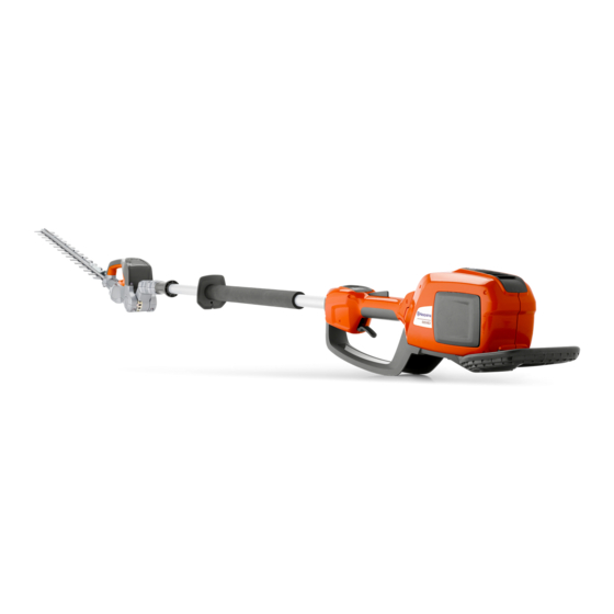
- Page 1 Workshop Manual 536LiHE3/520iHE3 English...
- Page 3 Diagnosis and Troubleshooting ..........18 Basic Dismantle/Assembly .............22 Safety Equipment ...............26 Repair Instructions ..............28 Husqvarna AB has a policy of continuous product development and therefore reserves the right to modify the design and appearance of products without prior notice. English – 3...
- Page 4 Index Index Basic Dismantle/Assembly 22 Service Data 12 Battery 23 Trigger guard 23 Service Tools 11 Wear guard under battery housing 23 Control handle 24 Safety Equipment 26 Battery housing 24 Dismantling the throttle trigger lock and throttle trigger 27 Assembling the throttle trigger lock and throttle Diagnosis and Troubleshooting 18 trigger 27 Remove the battery 19 Connect the diagnostic tool 19...
- Page 5 Introduction and safety regulations 2 Introduction and Safety Instructions Table of contents General information ............................... 7 Safety ..................................7 Target group ................................7 Modifications ................................7 Tools ..................................... 7 Structure ..................................7 Numbering ................................7 General instructions ............................... 8 Special instructions ..............................8 2.10 Limitations .................................
- Page 6 The figures are numbered 1, 2 etc. Usage is made evident in each section. The position references and figure numbers restart in each new section. Always use original Husqvarna: • Spare parts • Service tools • Accessories English – 6...
- Page 7 Use ear protection during testing. tions are not followed. 2.10 Limitations NOTE! This workshop manual is mainly intended for repair of pole hedge trimmer 536LiHE3. This box warns of material damage if the instructions are not followed. 7 – English...
- Page 8 Introduction and safety regulations 2.11 Symbols on the product 2.12 Symbols in the Workshop Manual The product's keypad has the following symbols. This symbol warns of personal injury when the instructions are not followed. Starting/Stopping savE / Battery saver mode Warning lamp/Fault indicator English –...
- Page 9 Technical Data 3 Technical Data Weight without battery Weight with battery (4.2 Ah) Ibs/kg Ibs/kg 536LiHE3 9.15 / 4.15 12.12 / 5.5 Cutting speed, rpm in Cutting speed, rpm in normal operation savE m/sec m/sec 4000 3200 536LiHE3 9 – English...
- Page 10 INSTRUCTION Common Service Tool The Common Service Tool (CST) is a service tool for Husqvarna products comprising Diagnostic Tool Kit (583 89 71-01) and software for the installation of a PC. If you have the previous "Engine Diagnostic Tool - AutoTune™" (576 69 23-01), it can be supplemented with the "Adapter Cable for Battery Products"...
- Page 11 Service data 5 Service Data 6 ~ 8 Nm 4 mm 3 ~ 4 Nm 10 mm Symbol used where The numbers by bolted components represent the tightening torque in grease is to be used. Tightening torque during inspection: 52 ft/lb (2.5 Nm) 11 –...
- Page 12 Service data Service Data English – 12...
- Page 13 Service data Service Data 13 – English...
- Page 14 Service data Service data LiHE3 S/N –20180400173 LiHE3 S/N 20180400173– English – 14...
- Page 15 Service data Service Data English – 15...
-
Page 16: Table Of Contents
Diagnosis and troubleshooting 6 Diagnosis and Troubleshooting Table of contents Remove the battery ..............................19 Connect the diagnostic tool ...........................19 No signal to diagnostic tool ...........................19 Troubleshooting the main switch ........................20 Troubleshooting the BLDC control unit ......................20 Overhaul ..................................20 16 – English... -
Page 17: Diagnosis And Troubleshooting
Diagnosis and troubleshooting 6 Diagnosis and Troubleshooting 6.1 Remove the battery Press in the catches and remove the battery. WARNING! Do not short circuit the battery! Never unscrew the battery! Never fit a damaged battery! Replace a damaged battery! 6.2 Connect the diagnostic tool NB! Ensure that the cutting unit is in working position when the tests in the Common service tool are being performed. -
Page 18: Troubleshooting The Main Switch
For products with S/N: -20180400173 (LiHE3). The switch used in professional battery products from Husqvarna has two functions, to supply cur- rent to the control unit and the electric motor, and act as a position sensor for the variable speed control. -
Page 19: Troubleshooting The Bldc Control Unit
Diagnosis and troubleshooting 6.5 Troubleshooting the Control Unit Check that the blade terminals and associated wires are not bent or damaged. (A) 4.8x0.8mm M phase (Green wire) (B) 4.8x0.8mm M phase (Black wire) (C) 4.8x0.8mm M phase (Red wire) 6.6 Overhaul Inspect the component parts of the product. - Page 20 Basic dismantle/assembly 7 Basic Dismantle/Assembly Table of contents Battery ...................................23 Trigger guard ................................23 Wear guard under battery housing ........................23 Control handle ................................24 Battery housing .................................24 20 – English...
- Page 21 Basic dismantle/assembly 7 Basic Dismantle/Assembly The steps described below are the basic steps that must be carried out before any other service or repair work or final assembly is possible. 7.1 Battery Press in the catches and remove the battery. Replace the battery once assembly has been completed.
- Page 22 Basic dismantle/assembly 7.4 Control handle Place something under the other handle half so that it does not come loose from the shaft. Loosen the screws (6x) and lift off the handle. Assemble in the reverse order. Tightening torque 2 ~ 3 Nm. 7.5 Battery housing Loosen the screws (4x) and lift off half the battery housing.
- Page 23 Safety equipment 8 Safety Equipment Table of contents Dismantling the throttle lock and throttle control ..................27 Assembling the throttle trigger lock and throttle trigger ................27 23 – English...
- Page 24 Safety equipment 8 Safety Equipment 8.1 Dismantling the throttle trigger lock and throttle trigger Dismantle the control handle as described in "7 Basic dismantle/assembly". Lift off the throttle trigger lock and the throttle trig- ger from their attachments in the handle. Cleaning and inspection •...
- Page 25 Repair Instructions 9 Repair Instructions Table of contents General repair instructions ..........................29 Dismantling the gear package ...........................29 Assembling the gear package ..........................31 Dismantling and assembling the cutting unit ....................33 Gears ....................................33 Dismantling the motor ............................34 Assembling the motor ............................34 Dismantling the cutting unit joint and cabling ....................35 Assembling the cutting unit joint and cabling .....................37 9.10 Dismantling and assembling the shaft and motor cabling ..............40...
-
Page 26: General Repair Instructions
Repair Instructions 9 Repair Instructions 9.1 General repair instructions NOTE! WARNING! Note how wires, components, etc., are posi- The battery must always be re- tioned before dismantling. moved for service/repair work and Make sure to position them correctly to may only be replaced once the avoid pinching when the product is reas- pole hedge trimmer has been fully assembled again! - Page 27 Repair Instructions Carefully separate the cutting unit and the shaft. Make sure the cables are not damaged. Dismantle the nuts holding the cutting unit. Dismantle the screws holding the gearbox cover, 6 pcs. Pull out the two screws holding the cutting unit in the gear.
-
Page 28: Assembling The Gear Package
Repair Instructions 9.3 Assembling the gear package Lubricate the parts marked in the figure. Lubricate each part with approx. 2.5 g grease. NOTE! Lubricate moving parts on gears and the cutting unit with grease so that they move easily! Use grease according to IPL. Assemble the cutting unit and gear package in the bevel gear. - Page 29 Repair Instructions Assemble the nuts holding the cutting unit. Carefully put together the cutting unit and the shaft. Make sure the cables are not damaged. Assemble the cover on the gear joint, 5 screws. Assemble the two cable shoes for the transport mode sensor.
-
Page 30: Dismantling And Assembling The Cutting Unit
Repair Instructions 9.4 Dismantling and assembling the cutting unit Loosen the circlip (A), lift off the washer (B), care- fully lift up the "hook" (C) and lift off the cutting unit. Loosen all the screws on the cutting unit and separate the parts as shown in the exploded view drawing. -
Page 31: Dismantling The Motor
Repair Instructions 9.6 Dismantling the motor Dismantle the cutting unit and gear package ac- cording to 9.2 Dismantling the gear package on page 26 Loosen the circlip using circlip pliers. Dismantle the motor by pulling the flywheel and the motor out of their mounting on the bevel gear body. 9.7 Assembling the motor Always use a new circlip. -
Page 32: Dismantling The Cutting Unit Joint And Cabling
Repair Instructions 9.8 Dismantling the cutting unit joint and cabling Dismantle the cutting unit and gear package according to 9.2 Dismantling the gear package on page 26 Refers to side without cabling. Pry off the lockwasher holding the cabling in place in the lower cover. - Page 33 Repair Instructions Refers to cabling side. Loosen the clamp (1). Loosen the bushing (2). Take care not to damage the cabling. Dismantle the screws holding the upper angle joint cover, 5 pcs. Dismantle the screw holding the locking pin for the angular adjustment of the cutting unit.
-
Page 34: Assembling The Cutting Unit Joint And Cabling
Repair Instructions Dismantle the positioning handle. Pull the handle away from the shaft. If the cabling must be replaced, the connector for the transport mode sensor and the control board must be unplugged. Also loosen the cables to the wiring harness to the control board (A, B, C). - Page 35 Repair Instructions Work the cabling, one wire at a time, through the angle joint. NB! Exercise care so that the cabling is not damaged. Assemble the lower angle joint cover. Assemble the screw holding the locking pin for the angular adjustment of the cutting unit. Assemble the screws holding the upper angle joint cover, 5 pcs.
- Page 36 Repair Instructions Assemble the indexing ring (4) Assemble the bushing (3). Assemble the clamp (2). Assemble the joint for the transport mode sensor (1). Assemble the lower joint cover. Assemble the adjusting screw used to adjust the inertia of the angle joint. Refers to side without cabling.
-
Page 37: Dismantling The Main Switch
Repair Instructions 9.10 Dismantling the shaft and motor cabling Dismantle the trigger guard, handle, battery hous- ing as described in 9.1 General repair instructions on page 26. Dismantle the clamp holding the shaft. Unplug the connector for the control unit and to the transport sensor. - Page 38 Repair instructions For products with S/N: 20180400173- (LiHE3). Dismantle the control handle as described in "6 Basic dismantle/assembly" on page 16. Dismantle the throttle trigger lock and throttle trig- ger as described in "7.1 Dismantling the throttle trigger lock and throttle trigger" on page 18. Lift out the main switch and disconnect cable (A).
-
Page 39: Assembling The Main Switch
Repair Instructions 9.13 Assembling the main switch For products with S/N: -20180400173 (LiHE3). Connect the contact (C) to the main switch. NB! Make sure to apply grease to the contact surfaces and also the connector. Connect cable (A) and place the main switch in the battery housing. -
Page 40: Dismantling The Control Cabling
Repair Instructions 9.14 Dismantling the control cabling NB! Use the CST to check the functions before dismantling. For products with S/N: -20180400173 (LiHE3). NOTE! Note how wires, components, etc., are posi- tioned before dismantling. Make sure to position them correctly to avoid pinching when the pole saw is reassembled. - Page 41 Repair Instructions For products with S/N: 20180400173- (LiHE3). NOTE! Note how wires, components, etc., are posi- tioned before dismantling. Make sure to position them correctly to avoid pinching when the pole saw is reassembled. Dismantle the control handle as described in "6 Basic dismantle/assembly"...
- Page 42 Repair Instructions 9.16 Assembling the control cable - all models We recommend dismantling the control unit before assembling the control cabling, see "8.19 Disman- tling the control unit" on page 46. For products with S/N: -20180400173 (LiHE3). Connect the connector to the control unit. •...
- Page 43 Repair Instructions We recommend dismantling the control unit before assembling the control cabling, see "8.19 Dismantling the control unit" on page 46. For products with S/N: 20180400173- (LiHE3). Connect the connector to the control unit. • Make sure that it snaps into place. •...
-
Page 44: Dismantling The Control Unit
Repair Instructions 9.17 Dismantling the control unit NB! Use the CST to check the functions before dismantling. Dismantle the battery housing as described in "6 Basic dismantle/assembly" on page 16. Disconnect the connector to the motor. Loosen the screws (G) to the control unit and the screws (H) to the battery contact and lift out the entire unit and the fan. -
Page 45: Assembling The Control Unit
Repair Instructions 9.18 Assembling the control unit Connect the connector from the motor to the con- trol unit. Connect connector (D) to the control unit for the keypad, fan and main switch. Make sure the connector is plugged firmly into the control unit. •... - Page 46 Repair Instructions 9.17 Dismantling the battery connector Caution: The pin in the connector of the communica- tion cable is loose and can fall out. Remove the battery connector. Push out the pins with a screwdriver. Pull out the wires and connectors to the positive and negative terminals.
- Page 47 Repair Instructions 9.18 Assembling the battery connector Caution: The pin in the connector of the communica- tion cable is loose and can fall out. Push the communication cable connector into the plastic housing, if the battery connector has a commu- nication cable.
- Page 48 Repair Instructions 9.19 To disconnect the motor cables Caution: The connectors and the terminals can be damaged if you use pliers to disconnect the cables. Refer to SB B1180039A-07 for important information about the Air Conductor. Put a flat screwdriver below the connector. Push the connector staight up.
- Page 49 Put on the air conductor. Make sure that the black and yellow cables are between the motor and the cable holder 9.21 To connect the motor cables Caution: The connectors and the terminals can be damaged if you use pliers to connect the cables. Put the cable on the terminal.
- Page 50 10 Troubleshooting - 536LiHE3 Symptom Possible causes Recommended action The product cannot be activated. No Faulty battery 1. Check the battery by pressing the LEDs come on after pressing the on/ status button. At least one green off button. LED should light up. See also Bat-...
- Page 51 Warning triangle flashes continually Temperature too high 1. Wait for the product to cool down on keypad (min. 5 minutes) Temperature of control unit or bat- 2. Make sure neither the product nor tery too low the battery is colder than -10 C Water in main switch signal contact 3.
- Page 52 Troubleshooting 11 Troubleshooting - battery and charger Symptom Possible causes Recommended action No LEDs come on on the battery Faulty battery Replace the battery. after pressing the status button. A warning triangle lights up solid red Faulty battery Replace the battery. on the battery when the status button is pressed.
- Page 53 Troubleshooting - Appendix 11 Troubleshooting - Appendix 1. Power connectors Make sure connectors are free from dirt and that metal surfaces are not damaged. Pay certain attention to the connection tabs. Power connectors have the same basic design on prod- uct, battery and charger.
- Page 54 Troubleshooting - Appendix 3. Main switch signal connector with grease For products with S/N: -20180400173 (LiHE3). Apply grease to the contact surfaces and also the connector. For products with S/N: 20180400173- (LiHE3). No grease necessary. 4. Communication cables Make sure the three small communication cables are not loose or damaged.
- Page 55 Troubleshooting - Appendix 5. Motor and power connectors Make sure the three motor connectors and the two power connectors are properly connected to respective plastic housing. 6. 26-pin wiring cable Make sure the 26-pin wiring cable is properly as- sembled, dry and not damaged. See "8.18 Assem- bling the control cabling"...
- Page 56 Troubleshooting - annex 12 Troubleshooting - Annex 1. Current contacts Make sure the contacts are clean and that none of the metal surfaces are damaged. Take extra care in checking the connection tabs. The current contacts have the same basic design for product, battery and charger.
- Page 57 Troubleshooting - annexe 3. Main switch signal connector with grease S/N: -20180400173 Apply grease between the specified pins, grease should be applied between pins 1, 2 and 3, 4 in- side as well as outside. 4. Communication cables Make sure the three small communication cables are not loose or damaged.
- Page 58 Troubleshooting - annex 5. Motor and power connectors Make sure the three motor connectors and the two power connectors are properly connected to respective plastic housing. 6. 26-pin wiring cable Make sure the 26-pin wiring cable is properly as- sembled, dry and not damaged. English –...
- Page 59 • 115 87 83-26 2018W15...