Siemens MICROMASTER 411 Operating Instructions Manual
Siemens welding system - ac/dc welding inverter user manual
Hide thumbs
Also See for MICROMASTER 411:
- Operating instructions manual (28 pages) ,
- Getting started manual (20 pages) ,
- Operating instructions manual (74 pages)

Related Manuals for Siemens MICROMASTER 411


Summary of Contents for Siemens MICROMASTER 411
- Page 1 MICROMASTER 411 & COMBIMASTER 411 Operating Instructions User Documentation 6SE6400-5CA00-0BP0 Issue 03/01...
- Page 2 MICROMASTER 411 / COMBIMASTER 411 Documentation Getting Started Guide Provides for Quick Commissioning of the Inverter. Operating Instructions Gives information about features of the MICROMASTER 411 / COMBIMASTER 411, Installation, Commissioning, Control modes, System Parameter structure, Troubleshooting, Specifications and available options of the MICROMASTER 411 / COMBIMASTER 411.
- Page 3 MICROMASTER 411 & COMBIMASTER 411 Operating Instructions User Documentation Valid for Release Inverter Type MICROMASTER 411 & COMBIMASTER 411 Issue 03/01 Issue 03/01 Control Version Overview Installation Commissioning Using the COMBIMASTER 411 MICROMASTER 411 System Parameters Troubleshooting Specifications Options Electro-Magnetic...
- Page 4 Further information is available on the Internet under: http://www.siemens.de/micromaster Approved Siemens Quality for Software and Training is to DIN ISO 14001, Reg. No. 2160-01 The reproduction, transmission or use of this document, or its contents is not permitted unless authorized in writing.
- Page 5 Customers can access technical and general information at: http://www.siemens.de/micromaster Contact address Should any questions or problems arise while reading this manual, please contact the Siemens office concerned using the form provided at the back this manual. MICROMASTER 411 & COMBIMASTER 411 6SE6400-5CA00-0BP0 Operating Instructions...
- Page 6 Earth voltage. This connection is normally used to ground the motor. Use for intended purpose only The equipment may be used only for the application stated in the manual and only in conjunction with devices and components recommended and authorized by Siemens. MICROMASTER 411 & COMBIMASTER 411 Operating Instructions 6SE6400-5CA00-0BP0...
-
Page 7: Safety Instructions
It is not permissible to open the equipment until 5 minutes after the power has been removed. HP ratings are based on the Siemens 1LA motors and are given for guidance only; they do not necessarily comply with UL or NEMA HP ratings. - Page 8 CAUTION Protect the inverter against physical shocks and vibration during transport and storage. Also be sure to protect it against water (rainfall) and excessive temperatures (see Table on page 94). MICROMASTER 411 & COMBIMASTER 411 Operating Instructions 6SE6400-5CA00-0BP0...
- Page 9 The connection of power, motor and control cables to the inverter must be carried out as shown in Figure 2-10 respectively, to prevent inductive and capacitive interference from affecting the correct functioning of the inverter. MICROMASTER 411 & COMBIMASTER 411 6SE6400-5CA00-0BP0 Operating Instructions...
- Page 10 60204, 9.2.5.4) Repair WARNING Repairs on equipment may only be carried out by Siemens Service, by repair centers authorized by Siemens or by qualified personnel who are thoroughly acquainted with all the warnings and operating procedures contained in this manual.
-
Page 11: Table Of Contents
Block Diagram ... 43 General Information... 44 Commissioning Procedure Overview ... 45 General operation... 56 Using the MICROMASTER 411 / COMBIMASTER 411 ... 61 Frequency Setpoint ... 62 Command Sources (P0700)... 63 OFF and Braking Functions ... 63 Control Modes (P1300) ... 65 Faults and warnings ... - Page 12 PROFIBUS Module ... 149 10.15 Variant Independent Options ... 152 Appendices... 155 Applicable Standards ... 155 List of Abbreviations... 156 MICROMASTER 411 / COMBIMASTER 411 Parts Identification ... 157 Index ... 158 MICROMASTER 411 & COMBIMASTER 411 Operating Instructions 6SE6400-5CA00-0BP0...
- Page 13 Power Supply & Motor Terminal Wire Sizes/Tightening Torques ...96 Table 7-5 Fixing Screw Recommended Tightening Torque ...96 Table 7-6 MICROMASTER 411/COMBIMASTER 411 Fuses and Circuit Breakers ...97 Table 8-1 Key to Programming Options...100 Table 9-1 Environment - General Industrial ...111 Table 9-2 Environment - Filtered Industrial ...111...
- Page 14 Figure 10-14 DC Braking ...133 Figure 10-15 Compound Braking ...134 Figure 10-16 Reduktionsfaktoren durch die Umgebungstemperatur...135 Figure 10-17 Derating with Altitude ...135 Figure 10-18 Power Losses MICROMASTER 411 / COMBIMASTER 411 ...146 MICROMASTER 411 & COMBIMASTER 411 Operating Instructions 6SE6400-5CA00-0BP0...
-
Page 15: Overview
Overview This Chapter contains: A summary of the major features of the COMBIMASTER 411 & MICROMASTER 411 range. MICROMASTER 411 / COMBIMASTER 411 ... 16 Design Features ... 17 MICROMASTER 411 & COMBIMASTER 411 6SE6400-5CA00-0BP0 Operating Instructions... -
Page 16: Micromaster 411 / Combimaster 411
COMBIMASTER 411 provides for a ready to use Inverter/Motor combination unit MICROMASTER 411 offers an Inverter for adaptation to a compatible motor with terminal boxes of size GK030. Inverters are available in ranges 370 W to 3.0 kW 380/480 V AC for three phase units. -
Page 17: Design Features
External options for PC communications, Basic Operator Panel (BOP), Advanced Operator Panel (AOP), PROFIBUS communications module Option for integrated class B-filter (interference emission class A) Optional housing for installing PROFIBUS module and EM control module MICROMASTER 411 & COMBIMASTER 411 6SE6400-5CA00-0BP0 Operating Instructions... -
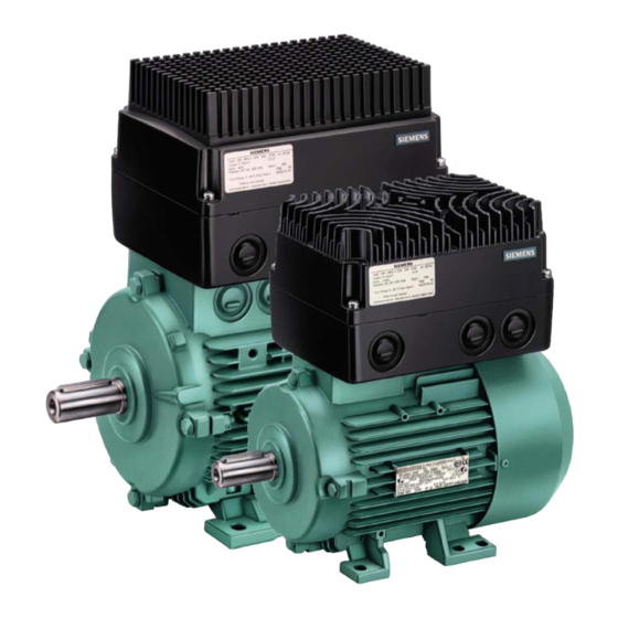
Page 18: Figure 1-1 Micromaster 411 And Combimaster 411 Variable Frequency Inverters
Control with Proportional-Integral control function (PI) Multi-point V/f characteristic Protection characteristics MICROMASTER 411: Type of protection up to IP66 (comparable to NEMA 4X) COMBIMASTER 411: Type of protection up to IP55 (comparable to NEMA 4) Overvoltage/undervoltage protection Overtemperature protection for the inverter... -
Page 19: Installation
Wiring guidelines to minimize the effects of EMI Details concerning electrical installation Installation after a Period of Storage... 21 Ambient operating conditions... 22 Mechanical Installation MICROMASTER 411... 23 Mechanical Installation COMBIMASTER 411... 30 Electrical Installation... 33 MICROMASTER 411 & COMBIMASTER 411... - Page 20 The connection of power and motor cables to the inverter must be carried out as shown in Figure 2-10 to prevent inductive and capacitive interference from affecting the correct functioning of the inverter. MICROMASTER 411 & COMBIMASTER 411 Operating Instructions 6SE6400-5CA00-0BP0...
-
Page 21: Installation After A Period Of Storage
Following a prolonged period of storage, you must reform the capacitors in the inverter. The requirements are listed below. Voltage Figure 2-1 Forming MICROMASTER 411 & COMBIMASTER 411 6SE6400-5CA00-0BP0 Storage period less than 1 year: Storage period 1 to 2 years: Storage period 2 to 3 years:... -
Page 22: Ambient Operating Conditions
Do not install the inverter near sources of electromagnetic radiation. Overheating MICROMASTER 411 / COMBIMASTER 411 are cooled by natural convection. Mount the inverter with the heatsink fins above to ensure optimum cooling. Mounting the inverter with the heatsink upside down is not allowed. -
Page 23: Mechanical Installation Micromaster 411
2.3.1 Preparation Remove the MICROMASTER 411 installation kit from the packing. Check packing box contents against the advice note supplied. The installation kit should comprise the following items: Inverter cover Terminal Housing Filter Module &... -
Page 24: Installation Procedure
Installation Procedure NOTE (MICROMASTER 411 ONLY): Prior to installation it may be necessary to fit an Adaptation Plate to a non-Siemens motor. The Adaptation Plate is prepared by the respective motor manufacturer. Normally the Adaptation Plate makes use of the existing motor gasket. -
Page 25: Figure 2-2 Micromaster 411, Internal Layout
Power Supply Terminals Cable Gland (Control) Terminal Housing (CSB) (Cable glands shown in preferred positions) Figure 2-2 MICROMASTER 411, Internal Layout MICROMASTER 411 & COMBIMASTER 411 6SE6400-5CA00-0BP0 Inverter Cover (CSB) Motor Terminals Control Terminals Operating Instructions Filter Module Output Relay... -
Page 26: Table 2-1 Micromaster 411 Dimension Detail
MICROMASTER 411 Dimensional Detail Figure 2-3 MICROMASTER 411 Case Size B Dimensions Figure 2-4 MICROMASTER 411 Case Size C Dimensions Table 2-1 MICROMASTER 411 Dimension Detail Height (H) Case Size (Inches) 135.6 (5.31) 170.6 (6.61) Width (W) Depth (D) Weight... -
Page 27: Figure 2-5 Cable Glands
3. After the knockout has been removed it should be safely discarded and the cable glands fitted as shown in Figure 2-6. MICROMASTER 411 & COMBIMASTER 411 6SE6400-5CA00-0BP0 Terminal Housing Figure 2-6 Operating Instructions Installation of Cable Gland... -
Page 28: Table 2-2 Gland Plate Detail
MICROMASTER 411 – Cable Gland Dimensions. Figure 2-7 MICROMASTER 411 Gland Dimensions Table 2-2 Gland Plate Detail Case Size (inch) 42,9 (1,68) 43,0 (1,69) (inch) (inch) (inch) 82,9 175,0 27,6 (3,26) (6,89) (1,09) 83,0 203,4 38,3 (3,27) (8,01) (1,51) MICROMASTER 411 & COMBIMASTER 411... - Page 29 2.3.5 Mounting the Inverter on a Siemens Motor Filter Board Captive Retaining Screws 2.3.6 Wall Mounting the Inverter Wall mounting of MICROMASTER 411 see Section 8.10. MICROMASTER 411 & COMBIMASTER 411 6SE6400-5CA00-0BP0 Operating Instructions...
-
Page 30: Mechanical Installation Combimaster 411
5. Any auxiliary equipment that might be fitted (e.g. mechanical brake) is in working order. 6. Protection guards are installed around all moving and live parts and any relevant safety notices displayed. MICROMASTER 411 & COMBIMASTER 411 Operating Instructions 6SE6400-5CA00-0BP0... -
Page 31: Figure 2-8 Combimaster 411 Case Size B Dimensional Detail
1. All dimensions given in millimeters (and inches). 2. MF dimensions use Motor construction type IMB3. Figure 2-8 COMBIMASTER 411 Case Size B Dimensional Detail MICROMASTER 411 & COMBIMASTER 411 6SE6400-5CA00-0BP0 Frame size 90S and 90L have feet with 2 holes each at the non-drive end. -
Page 32: Figure 2-9 Combimaster 411 Case Size B Dimensional Detail
2. MF dimensions use Motor construction type IMB3. Figure 2-9 COMBIMASTER 411 Case Size B Dimensional Detail 201.1 349.5 (6.5) (13.8) (2.2) (3.9) (7.7) (14.6) (2.5) (5.5) MICROMASTER 411 & COMBIMASTER 411 170.6 (5.5) (2.0) (0.9) (0.4) (6.3) (2.4) (1.1) (0.5) Operating Instructions 6SE6400-5CA00-0BP0... -
Page 33: Electrical Installation
Operation with Residual Current Device If an RCD (also referred to as ELCB or RCCB) is fitted, the MICROMASTER 411 Inverters will operate without nuisance tripping, provided that: A type B RCD is used. -
Page 34: Line And Motor Connections
Access to the power and motor terminals The procedure for accessing the power and motor terminals on the COMBIMASTER 411 & MICROMASTER 411 Inverter is illustrated in Figure 2-10. C copper wire only. For tightening torque see Section 7.3. MICROMASTER 411 & COMBIMASTER 411... -
Page 35: Power Connections
Motor wires should be connected in either star or delta configuration in accordance with the motor rating plate. For cable size and rating refer to Section 7.3. MICROMASTER 411 & COMBIMASTER 411 6SE6400-5CA00-0BP0 C copper wire only. Use a 4-core cable. If crimp terminals are... -
Page 36: Figure 2-10 Motor And Power Supply Connections
2 Installation Issue 03/01 Figure 2-10 Motor and Power Supply Connections MICROMASTER 411 & COMBIMASTER 411 Operating Instructions 6SE6400-5CA00-0BP0... -
Page 37: Figure 2-11 Control Terminals
Terminal DIN 1 DIN 2 DIN 3 AIN (-/+) Option: DIN 4 Output Relay Figure 2-11 Control Terminals MICROMASTER 411 & COMBIMASTER 411 6SE6400-5CA00-0BP0 Inputs Parameter P0701 = ‘1’ P0702 = ‘12’ P0703 = ‘9’ P0756 = 0 P0704 P0731 = ’52.3’... -
Page 38: Figure 2-12 Ptc Connections
NOTE DIN 3 must be configured to read the PTC input [(P0703 = 29) (external trip)] Figure 2-12 PTC Connections PTC Resistor connects between terminals 4 (+24 V) and 3 (DIN 3). MICROMASTER 411 & COMBIMASTER 411 Operating Instructions 6SE6400-5CA00-0BP0... - Page 39 Screened motor cables should be used when the motor is mounted separately from the inverter. Maximum motor cable length is 5 meters (16.40 feet). WARNING Safety regulations must not be compromised when installing inverters! MICROMASTER 411 & COMBIMASTER 411 6SE6400-5CA00-0BP0 Operating Instructions right angles.
- Page 40 2 Installation Issue 03/01 MICROMASTER 411 & COMBIMASTER 411 Operating Instructions 6SE6400-5CA00-0BP0...
-
Page 41: Commissioning
Commissioning This Chapter contains: A schematic diagram of the MICROMASTER 411 / COMBIMASTER 411 An overview of the commissioning options and the display and operator panels An overview of quick commissioing of the MICROMASTER 411 / COMBIMASTER 411 Block Diagram ... 43 General Information... - Page 42 Only qualified personnel may enter settings in the control panels. Particular attention must be paid to safety precautions and warnings at all times. The COMBIMASTER 411 & MICROMASTER 411 is supplied with default parameter settings that cover the following requirements: The motor rating data, voltage, current and frequency are all compatible with the inverter data.
-
Page 43: Block Diagram
Switching voltage must b DIN4 24 V max – +24 V(100 mA max) ?????? V or 0 V (isolated) Figure 3-1 COMBIMASTER 411 & MICROMASTER 411 Block Diagram MICROMASTER 411 & COMBIMASTER 411 6SE6400-5CA00-0BP0 Motor Potentiometer Serial Interface RS232 Brake... -
Page 44: General Information
Advanced Operator Panel (AOP) or the set-up software contained on the Docu-CD is required. The COMBIMASTER 411/MICROMASTER 411 can additionally be integrated into automation systems via the PROFIBUS module (option) or USS interface. When delivered the inverter has a frequency setpoint range of between 0 Hz and 50 Hz. -
Page 45: Commissioning Procedure Overview
Commissioning Procedure Overview Figure 3-2 MICROMASTER 411 / COMBIMASTER 411 Commissioning Guide MICROMASTER 411 & COMBIMASTER 411 6SE6400-5CA00-0BP0 Operating Instructions... -
Page 46: Table 3-1 Ramp Time Adjustment Jumpers
Using up to 5 jumpers allows ramp times to be set between 1 - 240 s. Also see Table 3-1. Table 3-1 Ramp Time Adjustment Jumpers Time [s] X20 Time [s] X20 MICROMASTER 411 & COMBIMASTER 411 Operating Instructions 6SE6400-5CA00-0BP0... -
Page 47: Table 3-2 Ramp Time Jumper Behaviour
Fan/Pump: M~n2 To change V/f curve from Linear to Quadratic curve. 60 Hz operation To change motor default settings from 50 Hz to 60 Hz. MICROMASTER 411 & COMBIMASTER 411 6SE6400-5CA00-0BP0 Reaction(s) of the inverter Power down Inverter uses the ramp times defined by the current... -
Page 48: Table 3-3 Control Circuit Jumper Settings
Parameters influenced by jumper will have jumper default values Parameters influenced by jumper are not changed Parameters influenced by jumper will have “jumper removed“ default values (normally factory default) Parameters influenced by jumper are not changed MICROMASTER 411 & COMBIMASTER 411 Operating Instructions 6SE6400-5CA00-0BP0... - Page 49 Further Commissioning via P0004 and P0003 An overview of the parameter structure is given in For a detailed description of parameters, see the NOTE We recommend the commissioning according this scheme. MICROMASTER 411 & COMBIMASTER 411 6SE6400-5CA00-0BP0 Section 5.3 Parameter List. Operating Instructions...
-
Page 50: Table 3-5 Default Settings For Bop Operation
411. The BOP is mounted in an Operator Panel Mounting Kit and connected to the COMBIMASTER 411 & MICROMASTER 411 via the serial interface (see Figure 3-9). The BOP can be used to configure several COMBIMASTER 411 & MICROMASTER 411 Inverters. -
Page 51: Figure 3-5 Basic Operator Panel Controls
Decrease value Figure 3-5 Basic Operator Panel Controls MICROMASTER 411 & COMBIMASTER 411 6SE6400-5CA00-0BP0 Effects The LCD displays the settings currently used by the inverter. Pressing the button starts the inverter. This button is disabled by default. To enable this button set P0700 = 1. -
Page 52: Figure 3-6 Changing Parameters Via The Bop
In some cases - when changing parameter values - the display on the BOP shows . This means the inverter is busy with tasks of higher priority. Step to the required value Step to the required value MICROMASTER 411 & COMBIMASTER 411 Result on display Result on display Operating Instructions 6SE6400-5CA00-0BP0... - Page 53 The function button may also be used to acknowledge a fault condition 3.3.4.2 Commissioning with the Advanced Operator Panel (AOP) local Siemens sales office for assistance. 3.3.4.3 Quick commissioning (P0010=1) Mechanical and electrical installation of the inverter must be completed before running „Quick Commissioning“.
- Page 54 0 s - 650 s Time taken for motor to decelerate from maximum motor frequency down to standstill. P3900 End Quick Commissioning No Quick Commissioning. Perform Quick Commissioning with factory reset of all other Parameters (Recommended). MICROMASTER 411 & COMBIMASTER 411 Operating Instructions 6SE6400-5CA00-0BP0...
-
Page 55: Figure 3-7 Typical Motor Rating Plate Example
1. The reset process can take up to 3 minutes to complete. 2. Refer to Parameter P0399 for description on saving motor data sets while performing a reset to the factory defaults. MICROMASTER 411 & COMBIMASTER 411 6SE6400-5CA00-0BP0 Operating Instructions... -
Page 56: General Operation
1.0 seconds while the inverter is stopped. 3. The inverter is programmed at the factory for standard applications on Siemens four-pole standard motors that have the same power rating as the inverters. When using other motors it is necessary to enter the specifications from the motor's rating plate. - Page 57 With the “Pot = Run” jumper fitted, the control potentiometer provides the ON/OFF command source. In order to provide the unit with a Run command the Control Potentiometer must be turned in a clockwise direction. To switch the unit OFF, turn the Control Potentiometer fully anti-clockwise (OFF position). WARNING...
-
Page 58: Figure 3-9 Connect Bop/Aop With The Micromaster 411
Link Cable, Part Number 6SE6401-1BL00-0AA0 to the Inverter serial comms port. This arrangement is shown in Figure 3-9. Figure 3-9 Connect BOP/AOP with the MICROMASTER 411 Prerequisites P0010 = 0 (in order to initiate the run command correctly). P0700 = 1 (enables the start/stop button on the BOP). - Page 59 Stopping the Motor When the inverter is being operated using the Run/Stop switch (connected to DIN1) setting the switch to OFF will override the potentiometer setting and bring the motor to a controlled stop. 3.4.4 If the Motor does not start up Refer to Chapter 6.
- Page 60 3 Commissioning Issue 03/01 MICROMASTER 411 & COMBIMASTER 411 Operating Instructions 6SE6400-5CA00-0BP0...
-
Page 61: Using The Micromaster 411 / Combimaster 411
Using the MICROMASTER 411 / COMBIMASTER 411 This Chapter contains: An explanation of the various methods of controlling the inverter A summary of the types of control of the inverter Frequency Setpoint ... 62 Command Sources (P0700)... 63 OFF and Braking Functions ... 63 Control Modes (P1300) ... -
Page 62: Frequency Setpoint
Additional external precautions must be taken, or facilities provided, to ensure safe operation, (e.g. independent limit switches, mechanical interlocks, etc.). COMBIMASTER 411/MICROMASTER 411 operate at high voltages. Certain parameter settings may cause the inverter to restart automatically after an input power failure. -
Page 63: Command Sources (P0700)
If the ON/OFF1 Command is set to more than one Digital input, only the last set Digital Input is active e.g. DIN3 active. OFF1 can be combined with DC braking or Compound braking. MICROMASTER 411 & COMBIMASTER 411 6SE6400-5CA00-0BP0 Terminal 1 (DIN 1): (P0700=2) - Page 64 Compound Braking is possible with both OFF1 and OFF3. For Compound Braking a DC component is added to the AC current. Set the braking current: see P1135 see P0701 to P0704 see P1233 0, DC braking will be active after see P1236 MICROMASTER 411 & COMBIMASTER 411 Operating Instructions 6SE6400-5CA00-0BP0...
-
Page 65: Control Modes (P1300)
Control Modes (P1300) The various modes of operation of the MICROMASTER 411 control the relation- ship between the speed of the motor and the voltage supplied by the inverter. A summary of the control modes available are listed below: Linear V/f control Can be used for variable and constant torque applications, such as conveyors and positive displacement pumps. - Page 66 4 Using the MICROMASTER 411 / COMBIMASTER 411 Issue 03/01 MICROMASTER 411 & COMBIMASTER 411 Operating Instructions 6SE6400-5CA00-0BP0...
-
Page 67: System Parameters
System Parameters This Chapter contains: An overview of the parameter structure of the MICROMASTER 411 / COMBIMASTER 411 A parameter list in short form Introduction to System Parameters... 68 Parameter Structure ... 69 Parameter List (short form) ... 70 MICROMASTER 411 & COMBIMASTER 411... -
Page 68: Introduction To System Parameters
Parameters can only be changed by using the Basic Operator Panel (BOP), the Advanced Operator Panel (AOP) or Serial Interface. NOTE Full details of the COMBIMASTER 411 /MICROMASTER 411 Parameters can be found in the separate document “COMBIMASTER 411/MICROMASTER 411 – Parameter List”. -
Page 69: Parameter Structure
Drive Features P0004 = 10 Setpoint Channel & Ramp Generator Figure 5-1 Parameter Structure with Filter (P0004) MICROMASTER 411 & COMBIMASTER 411 6SE6400-5CA00-0BP0 P0004 = 2 Inverter Unit Parameters level 1, 2, 3 and 4 P0004 = 2 Inverter Unit... -
Page 70: Parameter List (Short Form)
Act. power stack code number P0201 Power stack code number r0203 Act. inverter type r0204 Power stack features r0206 Rated inverter power [kW] / [hp] r0207 Rated inverter current Default Default Default Default MICROMASTER 411 & COMBIMASTER 411 Operating Instructions 6SE6400-5CA00-0BP0... - Page 71 P0611[1] Motor I2t time constant P0614[1] Motor I2t overload warning level P0640[1] Motor overload factor [%] P1910 Select motor data identification r1912[1] Identified stator resistance MICROMASTER 411 & COMBIMASTER 411 6SE6400-5CA00-0BP0 Default Default 3.25 0.75 0.000 50.00 1.000 1.000 4.00000 100.0...
- Page 72 BI: Disable additional setpoint P1110[1] BI: Inhibit neg. freq. setpoint P1113[1] BI: Reverse P1124[1] BI: Enable JOG ramp times P1140[1] BI: RFG enable P1141[1] BI: RFG start Default 52:3 722:0 19:1 19:13 19:14 722:1 MICROMASTER 411 & COMBIMASTER 411 Operating Instructions 6SE6400-5CA00-0BP0...
- Page 73 Inhibit reverse direction of MOP P1040[1] Setpoint of the MOP r1050 CO: Act. Output freq. of the MOP P1058[1] JOG frequency right P1059[1] JOG frequency left MICROMASTER 411 & COMBIMASTER 411 6SE6400-5CA00-0BP0 Default 722:2 19:13 19:14 100.0 Default 0.00 5.00 10.00...
- Page 74 Holding time after ramp down P1232[1] DC braking current P1233[1] Duration of DC braking Default 10.00 10.00 755:0 755:1 0.00 50.00 0.00 0.00 0.00 0.00 2.00 10.00 10.00 0.00 0.00 0.00 0.00 5.00 Default MICROMASTER 411 & COMBIMASTER 411 Operating Instructions 6SE6400-5CA00-0BP0...
- Page 75 P1340[1] Imax controller prop. gain P1341[1] Imax controller integral time r1343 CO: Imax controller freq. output r1344 CO: Imax controller volt. output P1350[1] Voltage soft start MICROMASTER 411 & COMBIMASTER 411 6SE6400-5CA00-0BP0 Default 10.00 Default 50.0 20.0 0.00 0.00 0.00 10.0...
- Page 76 P2051[4] CI: PZD to CB r2053[5] CB identification r2054[7] CB diagnosis r2090 BO: Control word 1 from CB r2091 BO: Control word 2 from CB Default 50.00 1000 0.10 52:0 52:0 52:0 MICROMASTER 411 & COMBIMASTER 411 Operating Instructions 6SE6400-5CA00-0BP0...
- Page 77 P2232 Inhibit rev. direct. of PID-MOP P2240[1] Setpoint of PID-MOP r2250 CO: Output setpoint of PID-MOP P2253[1] CI: PID setpoint P2254[1] CI: PID trim source MICROMASTER 411 & COMBIMASTER 411 6SE6400-5CA00-0BP0 Default 3.00 30.00 3.00 1.00 100.0 2000 Default 0.00 10.00...
- Page 78 Torque filtered timeconstant r2398 CO: Filtered torque r2399 CO/BO: Energy Saving status word Default 100.00 100.00 1.00 1.00 0.00 755:0 0.00 100.00 0.00 100.00 3.000 0.000 100.00 0.00 1.00 90.0 0.00 0.00 86:0 0.00 MICROMASTER 411 & COMBIMASTER 411 Operating Instructions 6SE6400-5CA00-0BP0...
-
Page 79: Troubleshooting
Notes on troubleshooting with the BOP A list of the alarms and fault messages Troubleshooting with the Inverter LED... 80 Troubleshooting with the Basic Operator Panel... 80 Faults and Alarms ... 81 MICROMASTER 411 & COMBIMASTER 411 6SE6400-5CA00-0BP0 Operating Instructions... -
Page 80: Troubleshooting With The Inverter Led
By using a switch between terminals 1 and 4 on the I/O board, the drive should now run to the defined setpoint (established by analog input and/or control potentiometer). NOTICE For the MICROMASTER 411 the motor data must relate to the inverter data power range and voltage. Status Power On / Ready... -
Page 81: Faults And Alarms
Required braking power must lie within specified limits NOTE Higher inertia requires longer ramp times; otherwise, apply braking resistor. F0003 UnderVoltage Possible Causes Main supply failed MICROMASTER 411 & COMBIMASTER 411 6SE6400-5CA00-0BP0 button on the BOP or AOP Operating Instructions OFF2 OFF2... - Page 82 F0015 Motor temperature signal lost Possible Causes Open or short circuit of motor temperature sensor. If signal loss is detected, temperature monitoring switches over to monitoring with the motor thermal model MICROMASTER 411 & COMBIMASTER 411 OFF2 OFF2 OFF1 OFF2...
- Page 83 2: Identified stator resistance less than 0.1 % or greater than 100 %. 3: Identified rotor resistance less than 0.1 % or greater than 100 %. 4: Identified stator reactance less than 50 % and greater than 500 % MICROMASTER 411 & COMBIMASTER 411 6SE6400-5CA00-0BP0 Operating Instructions...
- Page 84 Internal communications failure Diagnose & Remedy If fault persists, change inverter Contact Service Department F0070 CB setpoint fault Possible Causes Check if motor data in P0304 to P0311 are correct MICROMASTER 411 & COMBIMASTER 411 OFF2 OFF2 OFF2 OFF2 OFF2 OFF2...
- Page 85 Diagnose & Remedy Change value of P2268 Adjust feedback gain F0222 PID Feedback above max. value Possible Causes PID feedback above max. value P2267 Diagnose & Remedy MICROMASTER 411 & COMBIMASTER 411 6SE6400-5CA00-0BP0 Operating Instructions OFF2 OFF2 OFF2 OFF2 OFF2...
- Page 86 P2186 (lower torque threshold 1) P2187 (upper torque threshold 2) P2188 (lower torque threshold 2) P2189 (upper torque threshold 3 P2190 (lower torque threshold 3) P2192 (delay time for permitted deviation) MICROMASTER 411 & COMBIMASTER 411 OFF2 OFF2 Operating Instructions 6SE6400-5CA00-0BP0...
-
Page 87: Alarm Messages
Ambient temperature could be higher than specified for the inverter A0505 Inverter I Possible Causes Warning level (P0294) exceeded, output frequency and/or pulse frequency will be reduced if parameterized (P0290) Diagnose & Remedy Check the following: MICROMASTER 411 & COMBIMASTER 411 6SE6400-5CA00-0BP0 Operating Instructions... - Page 88 If encoder fitted, check correct encoder selected (check encoder set-up in P0400). Check connections between encoder and inverter Check encoder not faulty (select P1300 = 0, run at fixed speed, check encoder feedback signal in r0061) Increase encoder loss threshold in P0492 MICROMASTER 411 & COMBIMASTER 411 Operating Instructions 6SE6400-5CA00-0BP0...
- Page 89 CB (communication board) specific Diagnose & Remedy See CB user manual A0707 CB warning 8 Possible Causes CB (communication board) specific Diagnose & Remedy See CB user manual A0708 CB warning 9 Possible Causes MICROMASTER 411 & COMBIMASTER 411 6SE6400-5CA00-0BP0 Operating Instructions...
- Page 90 Fault value = 0: Parameter settings for output identical 1: Parameter settings for input identical 2: Parameter settings for input do not correspond to ADC type A0921 DAC parameters not set properly Possible Causes MICROMASTER 411 & COMBIMASTER 411 Operating Instructions 6SE6400-5CA00-0BP0...
- Page 91 P2185 (upper torque threshold 1) P2186 (lower torque threshold 1) P2187 (upper torque threshold 2) P2188 (lower torque threshold 2) P2189 (upper torque threshold 3) P2190 (lower torque threshold 3) P2192 (delay time for permitted deviation) MICROMASTER 411 & COMBIMASTER 411 6SE6400-5CA00-0BP0 Operating Instructions...
- Page 92 6 Troubleshooting Issue 03/01 MICROMASTER 411 & COMBIMASTER 411 Operating Instructions 6SE6400-5CA00-0BP0...
-
Page 93: Specifications
Specifications This Chapter contains: The common technical data to the MICROMASTER 411 / COMBIMASTER 411 Inverters The wire sizes and terminal torques Divided into several tables - an overview of the specific technical data of every MICROMASTER 411 / COMBIMASTER 411 Inverter Technische Daten ... -
Page 94: Technische Daten
Technische Daten Table 7-1 MICROMASTER 411 / COMBIMASTER 411, Leistungsdaten Eigenschaften Power supply Operating Voltage & Power Ranges Input Frequency Cos phi Inverter Efficiency Overload Capability Inrush Current Control Method Pulse Frequency Fixed Frequencies Skip Frequencies Setpoint Resolution Output Frequency Resolution... -
Page 95: Case Size Rating Information
Case Size Rating Information Table 7-2 Case Size B MICROMASTER 411 / COMBIMASTER 411 Frame size: 2 pole 4 pole Motor Output Rating Operating Input Voltage (rms) Operating Input Frequency Output Frequency 2 pole 4 pole Inrush Current Input Current (rms) -
Page 96: Tightening Torque, Cable Cross Sections For Power Supply And Motor Terminals
[Nm] [lbf.in] 21,3 (M5) [Nm] [lbf.in] (M3) [Nm] [lbf.in] (M3) [Nm] 1,5/2,5 M4/M5 [lbf.in] 10,6/21,3 M4/M5 MICROMASTER 411 & COMBIMASTER 411 Case Size C Case Size C (M5) (M5) 21,3 (M5) (M3) (M3) (M3) (M3) (M3) (M3) (M5) 21,3 (M5) -
Page 97: Fuses And Circuit Breakers
Fuses and Circuit Breakers Table 7-6 MICROMASTER 411/COMBIMASTER 411 Fuses and Circuit Breakers Inverter MICRO MICROMASTER 411 COMBIMASTER 411 (without filter) 380 V to 480 V 3 AC MICROMASTER 411 COMBIMASTER 411 (with Class B filter) 380 V to 480 V 3 AC MICROMASTER 411 &... -
Page 98: Micromaster 411 & Combimaster 411 Operating Instructions
7 Specifications Issue 03/01 MICROMASTER 411 & COMBIMASTER 411 Operating Instructions 6SE6400-5CA00-0BP0... -
Page 99: Options
Options An overview of the options available for the MICROMASTER 411 / COMBIMASTER 411 is given in this section. For further information about options, please refer to the catalog or the documentation CD. MICROMASTER 411/COMBIMASTER 411 User Options Description Basic Operator Panel (BOP) -
Page 100: Micromaster 411/Combimaster 411 Programming Options
3. Options 2 and 3 are for use with DriveMonitor Commissioning Software Tool. Option 2 Option 3 Programming Programming (without (with Isolation) Isolation) MICROMASTER 411 & COMBIMASTER 411 Option 4 Option 5 Desk Programming Door mounted of AOP for operator panel... -
Page 101: Basic Operator Panel (Bop) / Advanced Operator Panel (Aop)
Basic Operator Panel (BOP) / Advanced Operator Panel (AOP) Basic Operator Panel 6SE6400-0BP00-0AA0 Advanced Operator Panel 6SE6400-0AP00-0AA0 MICROMASTER 411 & COMBIMASTER 411 6SE6400-5CA00-0BP0 Desk Mounted BOP/AOP in Operator Panel Mounting Kit (6SE6401-1DF00-0AA0) Door Mounted BOP/AOP in BOP/AOP door mounting Kit... -
Page 102: Profibus Module
8 Options Issue 03/01 PROFIBUS Module MICROMASTER 411 & COMBIMASTER 411 Operating Instructions 6SE6400-5CA00-0BP0... -
Page 103: Em Brake Module
Issue 03/01 8 Options EM Brake Module MICROMASTER 411 & COMBIMASTER 411 Operating Instructions 6SE6400-5CA00-0BP0... -
Page 104: Micromaster 411 Operator Panel Mounting Kit
8 Options Issue 03/01 MICROMASTER 411 Operator Panel Mounting Kit MICROMASTER 411 & COMBIMASTER 411 Operating Instructions 6SE6400-5CA00-0BP0... -
Page 105: Pc To Inverter Connection Kit
Issue 03/01 8 Options PC to Inverter Connection Kit MICROMASTER 411 Operator Panel Mounting Kit (6SE6401-1DF00-0AA0) PC to Inverter Connection Kit (6SE6401-1PC00-0AA0) MICROMASTER 411 & COMBIMASTER 411 Operating Instructions 6SE6400-5CA00-0BP0... -
Page 106: Pc To Aop Connection Kit
PC to AOP Connection Kit (6SE6400-0AP00-0AA0) PC to AOP Connection Kit (6SE6400-0PA00-0AA0) MICROMASTER 411 & COMBIMASTER 411 Power Supply Adaptor Operating Instructions 6SE6400-5CA00-0BP0... -
Page 107: Door Mounting Kit For Single Inverter Control
Issue 03/01 8 Options Door Mounting Kit for Single Inverter control MICROMASTER 411 & COMBIMASTER 411 Operating Instructions 6SE6400-5CA00-0BP0... -
Page 108: Wall Mounting Kit For Micromaster 411
8.10 Wall Mounting Kit for MICROMASTER 411 Wall Mounting Kit (6SE6401-0WM00-0AA0) Contents: 1 x Wall Mounting Bracket 1 x Gortex Membrane 1 x Gasket 1 x Cable Gland 1 x Gland Fixing Plate 4 x Fixing Screws (M5 x 16 mm) MICROMASTER 411 &... -
Page 109: Electro-Magnetic Compatibility (Emc)
Electro-Magnetic Compatibility (EMC) This Chapter contains: EMC information. Electro-Magnetic Compatibility (EMC) ... 110 MICROMASTER 411 & COMBIMASTER 411 6SE6400-5CA00-0BP0 Operating Instructions... -
Page 110: Electro-Magnetic Compatibility (Emc)
EN 61000-3-2 "Limits for harmonic current emissions (equipment input <= 16 A per phase)". All Siemens variable speed drives of the MICROMASTER, MIDIMASTER, MICROMASTER Eco and COMBIMASTER ranges, which are classified as "Professional Equipment" within the terms of the standard, fulfill the requirements of the standard. -
Page 111: Table 9-1 Environment - General Industrial
Voltage Fluctuations, Dips, Unbalance, Frequency Variations Magnetic Fields Electrostatic Discharge Burst Interference Radio Frequency Electromagnetic Field, amplitude modulated Radio-frequency Electromagnetic Field, pulse modulated MICROMASTER 411 & COMBIMASTER 411 6SE6400-5CA00-0BP0 Standard Level EN 55011 Level A1 EN 61800-3 European Amendment EN61800-3-A13 EN 61000-4-2... -
Page 112: Table 9-3 Environment - Filtered For Residential, Commercial And Light Industry
Radio-frequency Electromagnetic Field, pulse modulated NOTICE MICROMASTER 411/COMBIMASTER 411 inverters are intended exclusively for professional applications. Therefore, they do not fall within the scope of the harmonics emissions specification EN 61000-3-2. Class A filtered inverters can be used in this environment under “Restricted Distribution”... -
Page 113: Table 9-4 Emc Compliance Table
* Denotes any value is allowed. 9.1.7 MICROMASTER 411 – EMC Compliance The MICROMASTER 411 inverters will, when correctly installed and put to their intended use, satisfy the requirements of the EEC Directive 89/336/EEC concerning electromagnetic compatibility. If the guidelines on installation to reduce the effects of electromagnetic interference are followed, the devices are sutiable for installation in machines. - Page 114 9 Electro-Magnetic Compatibility (EMC) Issue 03/01 MICROMASTER 411 & COMBIMASTER 411 Operating Instructions 6SE6400-5CA00-0BP0...
-
Page 115: Engineering Information
10.10 Use of MM4 Input Chokes... 146 10.11 Power Losses... 146 10.12 Shock and Vibration ... 147 10.13 PROFIBUS ... 148 10.14 PROFIBUS Module ... 149 10.15 Variant Independent Options ... 151 MICROMASTER 411 & COMBIMASTER 411 6SE6400-5CA00-0BP0 Operating Instructions... -
Page 116: Current Limit And Overload Operation
Figure 10-1 illustrates the interaction of parameters associated with current limit. Read Only parameters r0027, r0034, r0037 and r0067 help with fault diagnosis. MICROMASTER 411 & COMBIMASTER 411 Operating Instructions 6SE6400-5CA00-0BP0... -
Page 117: Table 10-1 Measured Current Monitoring Accuracy
Measured Current Monitoring Accuracy Inverter Switching frequency Load on inverter Frequency setpoint Scope current (long cable)* Drive current % difference (inverter/scope)* MICROMASTER 411 & COMBIMASTER 411 6SE6400-5CA00-0BP0 Frame Size B, 400 V 1,5 kW 4 kHz Nominal load 45 Hz 4,00 A... -
Page 118: Figure 10-2 Ptc Resistor Connections
PTC built in, or if two or three motors are connected to the inverter output and require individual protection. Figure 10-2 PTC Resistor Connections minimum, 1.5 k nominal, and 2 k MICROMASTER 411 & COMBIMASTER 411 and greater. The Operating Instructions 6SE6400-5CA00-0BP0... -
Page 119: Table 10-2 Trip Levels
Check to ensure you have matched the input supply to the inverter. If the supply voltage is too high, you may damage the inverter even if it trips. MICROMASTER 411 & COMBIMASTER 411 6SE6400-5CA00-0BP0 t limit to be enabled to protect the motor. -
Page 120: Control And Operating Modes
(e.g. P1310 = 100, P1312 = 100), to reduce the possibility of overheating. Voltage Boost increases voltage here t function, so boost may be reduced further if MICROMASTER 411 & COMBIMASTER 411 Frequency t function can be Operating Instructions 6SE6400-5CA00-0BP0... - Page 121 10.2.2.2 Implementation on MICROMASTER 411/COMBIMASTER 411 MICROMASTER 411/COMBIMASTER 411 have a built in PI controller that can be enabled by the user to allow for closed loop control. Once the PI controller is enabled (using P2200), the PI controller internally generates the motor frequency necessary to minimize the error between the PI setpoint and the PI feedback.
- Page 122 For the majority of applications, this will be in the form of an analogue sensor. The MICROMASTER 411/COMBIMASTER 411 has one analogue input, terminal connections 6 & 7, and the feedback signal can be connected to this input. The source of the PI feedback signal must then be defined using P2264 = 755 (source of PI feedback = analogue input 1).
- Page 123 (via the feedback signal) with the desired system behavior. The desired behavior is defined using a setpoint. The user selects the source of the setpoint with parameter P2253. MICROMASTER 411/COMBIMASTER 411 only have one analogue input and this is most commonly used for the feedback signal, so an internal digital setpoint is usually used.
-
Page 124: Figure 10-4 Quick Response With Overshoot: P2280 = 0.30; P2285 = 0.03 S
1 V = 10%. The different responses are achieved by varying the settings of P2280 and P2285. Figure 10-4 Quick response with overshoot: P2280 = 0.30; P2285 = 0.03 s Figure 10-5 Quick response with overshoot, but instability:P2280 = 0.55; P2285 = 0.03 s MICROMASTER 411 & COMBIMASTER 411 Operating Instructions 6SE6400-5CA00-0BP0... -
Page 125: Figure 10-6 Damped Response: P2280 = 0.20; P2285 = 0.15 S
P term (P2280) greater than 0.50. A block diagram showing the relationships and interaction between PI Setpoint and PI Feedback is shown in Figure 10-10 on page 128. MICROMASTER 411 & COMBIMASTER 411 6SE6400-5CA00-0BP0 Operating Instructions... -
Page 126: Figure 10-7 Response To 5 Hz Step: L = 100 Ms
To allow this, the following parameters are set: P2200 = 0 P1120 = 0,0 s P1121 = 0,0 s P1080 = 50.0 Hz. Figure 10-7 Response to 5 Hz step: L = 100 ms MICROMASTER 411 & COMBIMASTER 411 Operating Instructions 6SE6400-5CA00-0BP0... -
Page 127: Figure 10-8 Response To 5 Hz Step: T = 700 Ms
I time = 3L = 0.30 s = P2285 The PI controller should now be enabled (P2200 = 1). Figure 10-9 Step Response in PI control with P2280 = 9.84 and P2285 = 0.30 MICROMASTER 411 & COMBIMASTER 411 6SE6400-5CA00-0BP0 Operating Instructions... -
Page 128: Figure 10-10 Pi Basic Block Diagram
(P0003 = 3). These features are described in the Parameter List. P2254 P2253 BOP link P2253 COM link P2200 COM link ADC2 Figure 10-10 PI Basic Block Diagram to be reached. MICROMASTER 411 & COMBIMASTER 411 (P1080) and Motor control Output Operating Instructions 6SE6400-5CA00-0BP0... - Page 129 Energy Saving Mode, it is necessary to activate the Auto-restart function of the inverter (using P1210=6). NOTES Energy Saving Mode only operates in a positive direction. Energy Saving Setpoint must be greater than f MICROMASTER 411 & COMBIMASTER 411 6SE6400-5CA00-0BP0 Operating Instructions...
-
Page 130: Figure 10-11 Energy Saving Mode 1
P2391 is started. When the energy saving timer has expired, the inverter is ramped down to stop and enters energy saving mode (see diagram below). Figure 10-11 Energy Saving Mode 1 MICROMASTER 411 & COMBIMASTER 411 Operating Instructions 6SE6400-5CA00-0BP0... -
Page 131: Figure 10-12 Energy Saving Mode 2
BICO-Parameter P2396 to a normalized characteristic. limit p(t) x(t) r2398 P2395 P2396 f(t) Load f(t) (e.g. valve) Figure 10-12 Energy Saving Mode 2 MICROMASTER 411 & COMBIMASTER 411 6SE6400-5CA00-0BP0 P2394 P2395 P2397 r2398 v(t) u(t) limit P2393 P2273... -
Page 132: Braking
(regeneration) to return to the DC link. To overcome this possibility the MICROMASTER 411/COMBIMASTER 411 employs a number of methods to control braking. These options are described in the following paragraphs. -
Page 133: Figure 10-14 Dc Braking
10.3.2 Vdc Max Controller The MICROMASTER 411/COMBIMASTER 411 has a controller to limit the DC voltage (Vdc Max controller). When braking a load faster than would normally be possible, excess energy has to be dissipated. This energy is unable to go back into the input supply so the result is that the DC link voltage rises. -
Page 134: Figure 10-15 Compound Braking
When using Compound braking, the ramp-down time is defined and the level of current to be used in Compound Braking is defined using P1236. Figure 10-15 Compound Braking MICROMASTER 411 & COMBIMASTER 411 Operating Instructions 6SE6400-5CA00-0BP0... -
Page 135: Derating Factors
Permissible rated input voltage as a percentage of the nominal voltage 1000 2000 Installation altitude in meters above sea level Figure 10-17 Derating with Altitude MICROMASTER 411 & COMBIMASTER 411 6SE6400-5CA00-0BP0 10 20 Permissible rated output current as a percentage of the nominal current 3000... -
Page 136: Table 10-3 Derating With Switching Frequencies
10.4.3 Derating with Switching Frequency The default switching frequency of the MICROMASTER 411/COMBIMASTER 411 is 4 kHz. This is usually adequate for most applications and will allow full performance to be obtained from all products over the full temperature range. -
Page 137: Thermal Protection And Automatic De-Rating
The MICROMASTER 411 cannot be used on unearthed input supplies. 10.7 Lifetime of Inverters When the inverters are used in conjunction with Siemens motors (1LA7 and 1LA9) the liftetime of the inverter is >= 20,000 hours. MICROMASTER 411 & COMBIMASTER 411 6SE6400-5CA00-0BP0 t trip will occur (F0005). -
Page 138: Working With Binary Connectors (Bico)
(digital, analogue, serial etc.) and outputs (inverter current, frequency, analogue output, relays etc.). The MICROMASTER 411/COMBIMASTER 411 uses a simplified version of BiCo, (which is still very flexible) contained within the parameter set. The system can be set up without using additional software or hardware. - Page 139 Now the inverter will ramp between set points using the normal ramp time as set in P1120 and 1121. However, at switch off from digital input 1, the inverter will turn off with an OFF3, using the ramp rate set in P1135, which may be different to P1121.
- Page 140 10.8.3 Using Control and Status Words with BiCo Many MICROMASTER 411/COMBIMASTER 411 read only parameters consist of control words. The parameter is made up of a 16-bit number, each bit representing a particular value. For example, parameter P0052 (Status Word 1) gives various value settings such as Inverter ready (bit 0), or Motor Current Limit (bit b).
-
Page 141: Table 10-4 Bico Connections (R0019 To R0054)
2019 CIW CI: PZD to Comm-Link (USS) 2051 CIW CI: PZD to CB 2200 CIB BI: Enable PID controller 2253 CIF CI: PID setpoint 2254 CIF CI: PID trim source 2264 CIF CI: PID feedback MICROMASTER 411 & COMBIMASTER 411 6SE6400-5CA00-0BP0 Operating Instructions... -
Page 142: Table 10-5 Bico Connections (R0055 To R1119)
2019 CIW CI: PZD to Comm-Link (USS) 2051 CIW CI: PZD to CB 2200 CIB BI: Enable PID controller 2253 CIF CI: PID setpoint 2254 CIF CI: PID trim source 2264 CIF CI: PID feedback MICROMASTER 411 & COMBIMASTER 411 Operating Instructions 6SE6400-5CA00-0BP0... -
Page 143: Table 10-6 Bico Connections (R1170 To R2050)
2019 CIW CI: PZD to Comm-Link (USS) 2051 CIW CI: PZD to CB 2200 CIB BI: Enable PID controller 2253 CIF CI: PID setpoint 2254 CIF CI: PID trim source 2264 CIF CI: PID feedback MICROMASTER 411 & COMBIMASTER 411 6SE6400-5CA00-0BP0 Operating Instructions... -
Page 144: Table 10-7 Bico Connections (R2053 To R2294)
2019 CIW CI: PZD to Comm-Link (USS) 2051 CIW CI: PZD to CB 2200 CIB BI: Enable PID controller 2253 CIF CI: PID setpoint 2254 CIF CI: PID trim source 2264 CIF CI: PID feedback MICROMASTER 411 & COMBIMASTER 411 Operating Instructions 6SE6400-5CA00-0BP0... -
Page 145: Harmonic Currents
6SE6411-6BD21-1AA1 Class B 6SE6411-6UD21-5AA1 unfiltered 6SE6411-6BD21-5AA1 Class B 6SE6411-2UD22-2AA1 unfiltered 6SE6411-6BD22-2AA1 Class B 6SE6411-2UD23-0AA1 unfiltered 6SE6411-6BD23-0AA1 Class B MICROMASTER 411 & COMBIMASTER 411 6SE6400-5CA00-0BP0 Power CT Fundamental (kW) Amps Amps Amps 0.37 1.50 1.29 0.55 2.00 1.69 0.75 2.60 2.13... -
Page 146: Use Of Mm4 Input Chokes
The mains short-circuit power may be obtained from the power supply company, or may be read from the Type Plate of the supplying power transformer. 10.11 Power Losses Figure 10-18 shows the power loss for the MICROMASTER 411/COMBIMASTER 411 Inverters. Figure 10-18 Power Losses MICROMASTER 411 / COMBIMASTER 411 Output Frequency MICROMASTER 411 &... -
Page 147: Shock And Vibration
Class 2M2: Class 2M1: The inverter meets class 2M2 for Vibration stress and 2M1 for shock stress in product packaging. MICROMASTER 411 & COMBIMASTER 411 6SE6400-5CA00-0BP0 EN 60721-3-3 class 3M6 and 3M8 EN60068-2-6, test Fc Class 3M6: 10-58 Hz/ 0.15 mm, 58-200 Hz/ 2g Class 3M6: 10-58 Hz/ 0.15 mm, 58-200 Hz/ 2g... -
Page 148: Profibus
There are three versions of PROFIBUS: FMS, DP and PA and all these versions will work together. The most commonly used version is the DP version, intended for general industrial applications. This is the version supported by Siemens Drives. 10.13.2 Using the PROFIBUS In order to connect to a PROFIBUS system, a PROFIBUS module is required. -
Page 149: Profibus Module
10.14 PROFIBUS Module This option allows the MICROMASTER 411/COMBIMASTER 411 to be controlled via a PROFIBUS-DP serial bus (SINEC L2-DP). PROFIBUS-DP is a cost-effective high-speed serial communication system optimized for the actuator/sensor area where very short system reaction times are critical. -
Page 150: Table 10-9 Maximum Cable Lengths For Data Transfer Rates
For reliable operation of the serial bus system, the cable must be terminated at both ends using terminating resistors. Bus terminations with the MICROMASTER 411 PROFIBUS Module is achieved using the Bus Termination Switch (see above). Additionally, for 12 MBd operation, no stub length from the main bus cable is allowed. -
Page 151: Table 10-10 Technical Data - 411 Profibus Module
Dimensions H x W x D Degree of protection Maximum bus speed Table 10-11 PROFIBUS Ordering information Designation PROFIBUS module MICROMASTER 411 & COMBIMASTER 411 6SE6400-5CA00-0BP0 Description 107,8 mm x 128 mm x 40,5 mm IP66 12 MBaud Order No. -
Page 152: Variant Independent Options
10.15 Variant Independent Options Several options are available for use with Siemens Standard inverters. These are intended to assist product selection, installation and commissioning in certain applications. 10.15.1 Basic Operating Panel (BOP) MICROMASTER default settings can be changed through the Basic Operator Panel (BOP) drive option. - Page 153 BOP/AOP Door Mounting Kit for Single Inverter Control This kit is used to mount an operator panel in a cabinet door. It must be used in conjunction with a MICROMASTER 411 5 m cable assembly. The connecting line must be supplied by the user.
-
Page 155: Appendices
Siemens plc operates a quality and environmental management system, which complies with the requirements of ISO 14001. ISO 9001 Siemens plc operates a quality management system, which complies with the requirements of ISO 9001. MICROMASTER 411 & COMBIMASTER 411 6SE6400-5CA00-0BP0 commutated inverters Safety of machinery –... -
Page 156: List Of Abbreviations
Insulated Gate Bipolar Transistor Liquid Crystal Display Light Emitting Diode Motor Potentiometer Proportional and Integral Programmable Logic Controller Positive Temperature Coefficient RCCB Residual Current Circuit breaker Residual Current Device Relative Humidity Revolutions Per Minute MICROMASTER 411 & COMBIMASTER 411 Operating Instructions 6SE6400-5CA00-0BP0... -
Page 157: Micromaster 411 / Combimaster 411 Parts Identification
MICROMASTER 411 / COMBIMASTER 411 Parts Identification Item Description Inverter Cover Inverter Retaining Screw Sealing Gasket Filter Module retaining screws Filter Module Terminal Housing Gland Knock – outs Motor Terminal Box Motor Frame Motor Terminal Box Gasket Input Output Board Serial Interface Socket MICROMASTER 411 &... -
Page 158: Index
Dimensional Detail · 26, 31 Door Mounting Kit · 107 Electrical Installation · 33 Electro-Magnetic Compatibility general · 109, 110 self-certification · 110 technical construction file · 110 Electro-Magnetic Interference · 39 MICROMASTER 411 & COMBIMASTER 411 Operating Instructions 6SE6400-5CA00-0BP0... - Page 159 Installation of Cable Glands · 27 Installation Procedure · 24 Internal Overtemperature · 119 Internet Home Address · 5 Line and Motor Connections · 34 MICROMASTER 411 & COMBIMASTER 411 6SE6400-5CA00-0BP0 Line Connections · 34 Linear V/f control · 65 Main characteristics · 17 Mechanical Installation ·...
- Page 160 Warnings, cautions & notes Commissioning · 9 definitions · 6 Dismantling & Disposal · 10 general · 7 Operation · 10 Repair · 10 Transport & Storage · 8 Ziegler-Nichols · 126 MICROMASTER 411 & COMBIMASTER 411 Operating Instructions 6SE6400-5CA00-0BP0...
- Page 161 D-91050 Erlangen Federal Republic of Germany Email: Technical.documentation@con.siemens.co.uk From Name: Company/Service Department Address: Telephone: __________ / Telefax: ________ / MICROMASTER 411 & COMBIMASTER 411 6SE6400-5CA00-0BP0 Suggestions Corrections For Publication/Manual: MICROMASTER 411 & COMBIMASTER 411 User Documentation Operating Instructions Order Number:...
- Page 162 MICROMASTER 411 & COMBIMASTER 411 Operating Instructions 6SE6400-5CA00-0BP0...
- Page 163 Issue 03/01 Geräteansicht MICROMASTER 411 & COMBIMASTER 411 Operating Instructions 6SE6400-5CA00-0BP0...
- Page 164 Siemens AG Bereich Automation and Drives (A&D) Geschäftsgebiet Standard Drives (SD) Postfach 3269, D-91050 Erlangen Bundesrepublik Deutschland Siemens Aktiengesellschaft © Siemens AG, 2002 Subject to change without prior notice Order No.: 6SE6400-5CA00-0BP0 Date: 03/01...