
Related Manuals for Siemens MICROMASTER 440 Series


Summary of Contents for Siemens MICROMASTER 440 Series
- Page 1 MICROMASTER 440 Operating instructions Issue A1 User Documentation http://nicontrols.com...
- Page 2 N O R T H E R N INDUSTRIAL W W W . N I C O N T R O L S . C O M ESTABLISHED IN 1978 Northern Industrial Thwaites Close Blackburn Lancashire BB1 2QQ United Kingdom Cert No.
-
Page 3: Installation
MICROMASTER 440 DOCUMENTATION Getting Started Guide Is for quick commissioning with SDP and BOP. Operating Instructions Gives information about features of the MM440, Installation, Commissioning, Control modes, System Parameter structure, Troubleshooting, Specifications and available options of the MM440. Parameter List The Parameter List contains the description of all Parameters structured in functional order and a detailed description. - Page 4 Overview Installation Commissioning Using the MICROMASTER 440 MICROMASTER 440 System Parameters Operating instructions Troubleshooting User Documentation MICROMASTER 440 Specifications Available options Electro-Magnetic Compatibility Appendices Valid for Converter Type Control Version MICROMASTER 440 04.2001 Index Issue A1 http://nicontrols.com...
-
Page 5: Important Notice
Further information can be obtained from Internet website: http://www.siemens.de/micromaster Approved Siemens Quality for Software and Training Other functions not described in this document may be is to DIN ISO 9001, Reg. No. 2160-01 available. However, this fact shall not constitute an... - Page 6 Technical Support Nuremberg Tel: +49 (0) 180 5050 222 Fax: +49 (0) 180 5050 223 Email: techsupport@ad.siemens.de Monday to Friday: 7:00 am to 5:00 pm (local time) Internet Home Address Customers can access technical and general information at: http://www.siemens.de/micromaster MICROMASTER 440...
-
Page 7: Using The
Siemens. Contact address Should any questions or problems arise while reading this manual, please contact the Siemens office concerned using the form provided at the back this manual. MICROMASTER 440 Operating instructions 6SE6400-5CA00-0BP0... -
Page 8: Micromaster
It is not permissible to open the equipment until 5 minutes after the power has been removed. ♦ HP ratings are based on the Siemens 1LA motors and are given for guidance only; they do not necessarily comply with UL or NEMA HP ratings. - Page 9 Foreword International English Transport & Storage Warning ♦ Correct transport, storage, erection and mounting, as well as careful operation and maintenance are essential for proper and safe operation of the equipment. Caution ♦ Protect the inverter against physical shocks and vibration during transport and storage.
- Page 10 EN 60204, 9.2.5.4) Repair Warnings ♦ Repairs on equipment may only be carried out by Siemens Service, by repair centers authorized by Siemens or by qualified personnel who are thoroughly acquainted with all the warnings and operating procedures contained in this manual.
- Page 11 Foreword International English MICROMASTER 440 Operating instructions 6SE6400-5CA00-0BP0 http://nicontrols.com...
-
Page 12: Table Of Contents
International English Table of Contents Table of Contents Overview ........................ 15 The MICROMASTER 440 ..................16 Features ........................16 Installation ......................19 General........................21 Ambient operating conditions.................. 22 Mechanical Installation .................... 23 Electrical Installation....................25 Commissioning ..................... 31 Block Diagram ......................33 Commission Modes.................... - Page 13 Table of Contents International English A - Changing the Operator Panel ..................... 97 B - Removing Covers Frame Size A..................98 C - Removing the I/O Board ...................... 99 D - Removing Covers Frame Sizes B and C................100 E - Removal of Covers Frame Size D and E ................101 F - Removal of Covers Frame Size F..................
-
Page 14: Micromaster 440 Operating Instructions 6Se6400-5Ca00-0Bp0
International English Table of Contents List of Illustrations Figure 2-1 Drill pattern for MICROMASTER 440..................22 Figure 2-2 MICROMASTER 440 Connection Terminals ................26 Figure 2-3 Motor and Power Connections....................27 Figure 2-4 Wiring Guidelines to Minimize the Effects of EMI ..............29 Figure 3-1 Inverter block diagram ......................33 Figure 3-2 Panels available for the MICROMASTER 440 Inverter............34... - Page 15 Table of Contents International English MICROMASTER 440 Operating instructions 6SE6400-5CA00-0BP0 http://nicontrols.com...
-
Page 16: Overview
International English 1 Overview Overview This Chapter contains: A summary of the major features of the MICROMASTER 440 range. The MICROMASTER 440 ..................16 Features ........................16 MICROMASTER 440 Operating instructions 6SE6400-5CA00-0BP0 http://nicontrols.com... -
Page 17: The Micromaster 440
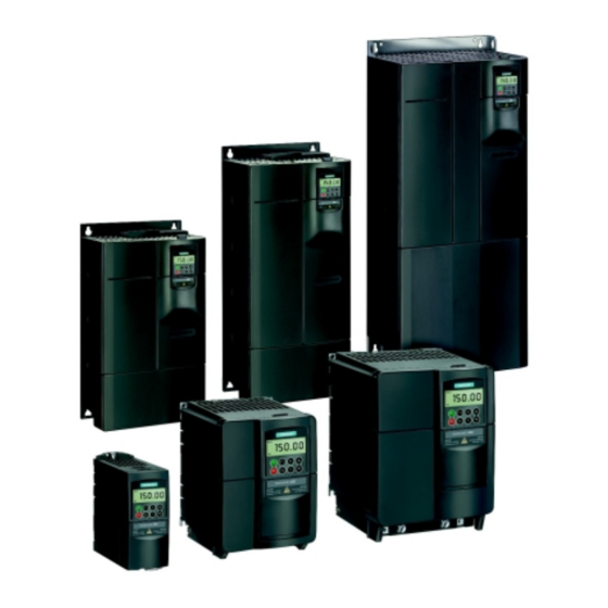
1 Overview International English The MICROMASTER 440 The MICROMASTER 440s are a range of frequency inverters for controlling the speed of three phase AC motors. The various models available range from the 120 W single-phase input to the 75 kW three phase input. The inverters are microprocessor-controlled and use state-of-the-art Insulated Gate BipoIar Transistor (IGBT) technology. - Page 18 International English 1 Overview Performance Characteristics Sensorless Vector Control Flux Current Control (FCC) for improved dynamic response and motor control Fast Current Limitation (FCL) for trip-free operation Built-in DC injection brake Compound braking to improve braking performance Acceleration/deceleration times with programmable smoothing Closed-loop control using PID (Proportional, Integral and Differential) control loop function, with auto-tuning Built-in braking chopper...
- Page 19 1 Overview International English MICROMASTER 440 Operating instructions 6SE6400-5CA00-0BP0 http://nicontrols.com...
-
Page 20: Installation
International English 2 Installation Installation This Chapter contains: General data relating to installation Dimensions of Inverter Wiring guidelines to minimize the effects of EMI Details concerning electrical installation General........................21 Ambient operating conditions.................. 22 Mechanical Installation .................... 23 Electrical Installation....................25 MICROMASTER 440 Operating instructions 6SE6400-5CA00-0BP0... - Page 21 2 Installation International English Warnings ♦ Work on the device/system by unqualified personnel or failure to comply with warnings can result in severe personal injury or serious damage to material. Only suitably qualified personnel trained in the setup, installation, commissioning and operation of the product should carry out work on the device/system.
-
Page 22: General
International English 2 Installation General Installation after a Period of Storage Following a prolonged period of storage, you must reform the capacitors in the inverter. It is important that the time of storage is calculated from the time of manufacture and not the time of delivery. The requirements are listed below. Period of Preparation Required Action... -
Page 23: Ambient Operating Conditions
2 Installation International English Ambient operating conditions Temperature Frame Size Min. [° ° ° ° C] Max. [° ° ° ° C] Max. (Variable Torque) [° ° ° ° C] Note The variable torque rating is the capability of the inverter to increase the nominal power output for use with pump and fan applications. -
Page 24: Mechanical Installation
International English 2 Installation Mechanical Installation Warning THIS EQUIPMENT MUST BE GROUNDED. ♦ To ensure the safe operation of the equipment, it must be installed and commissioned by qualified personnel in full compliance with the warnings laid down in these operating instructions. ♦... - Page 25 2 Installation International English Table 2-1 Dimensions and Torques of MM440 (all frame sizes) Overall Dimensions Frame- Fixing Method Tightening Torque Size Height Width Depth 2 x M4 Bolts 2 x M4 Nuts 2.5 Nm 173 mm 73 mm 149 mm 2 x M4 Washers with washers fitted Connecting to DIN rail...
-
Page 26: Electrical Installation
International English 2 Installation Electrical Installation Warning THIS EQUIPMENT MUST BE GROUNDED. ♦ To ensure the safe operation of the equipment, it must be installed and commissioned by qualified personnel in full compliance with the warnings laid down in these operating instructions. ♦... - Page 27 2 Installation International English Operation with long cables Caution The control, power supply and motor leads must be laid separately. Do not feed them through the same cable conduit/trunking. Never use high voltage insulation test equipment on cables connected to the inverter. All inverters will operate at full specification with cable lengths up to 50 m screened or 100 m unscreened.
- Page 28 International English 2 Installation Ground Ground Ground Ground FRAME SIZE A FRAME SIZE B & C Ground Ground FRAME SIZE D & E DC+ DC+ Ground Ground FRAME SIZE F Figure 2-2 MICROMASTER 440 Connection Terminals MICROMASTER 440 Operating instructions 6SE6400-5CA00-0BP0 http://nicontrols.com...
-
Page 29: Figure 2-3 Motor And Power Connections
2 Installation International English CABLE SCREENING OPTIONAL FILTER (Class B only) CONTACTOR MICROMASTER MOTOR FUSE L/L1 N/L2 SINGLE PHASE TYPICAL INSTALLATION CABLE SCREENING OPTIONAL FILTER CONTACTOR MICROMASTER MOTOR FUSE THREE PHASE Figure 2-3 Motor and Power Connections MICROMASTER 440 Operating instructions 6SE6400-5CA00-0BP0 http://nicontrols.com... - Page 30 International English 2 Installation 2.4.3 Avoiding Electro-Magnetic Interference (EMI) The inverters are designed to operate in an industrial environment where a high level of EMI can be expected. Usually, good installation practices will ensure safe and trouble-free operation. If you encounter problems, follow the guidelines stated below.
-
Page 31: Figure 2-4 Wiring Guidelines To Minimize The Effects Of Emi
2 Installation International English Screening without a Gland Plate Should a Gland Plate not be available, then the inverter can be screened using the methodology shown in Figure 2-4. Figure 2-4 Wiring Guidelines to Minimize the Effects of EMI Legend Mains power input Control cable Motor cable to I/O board... -
Page 32: Commissioning
International English 3 Commissioning Commissioning This Chapter contains: Description of the front panel controls A brief description of the optional front panels available and an explanation of the operation of the Basic Operator Panel (BOP) An 8-step guide at the end of the Chapter, which provides a simple procedure for changing parameters Block Diagram ...................... - Page 33 3 Commissioning International English Warning ♦ MICROMASTERS operate at high voltages. ♦ When operating electrical devices, it is impossible to avoid applying hazardous voltages to certain parts of the equipment. ♦ Emergency Stop facilities according to EN 60204 IEC 204 (VDE 0113) must remain operative in all operating modes of the control equipment.
-
Page 34: Block Diagram
International English 3 Commissioning Block Diagram 1 - 3 AC 200 - 240 V 3 AC 380 - 480 V 3 AC 500 - 600 V L/L1, N/L2 +10 V L/L1, N/L2, L3 4.7k 9 AIN1+ MINIMUM AIN1- 150.00 AIN2+ Serial Protocol AIN2-... -
Page 35: Commission Modes
The motor rating data; voltage, current and frequency data is keyed into the inverter to ensure that the motor is compatible with the inverter. (A standard Siemens motor is recommended). Linear V/f motor speed, controlled by an analogue potentiometer. Maximum speed 3000 min with 50 Hz (3600 min-1 with 60 Hz);... - Page 36 International English 3 Commissioning Front Panels for the MICROMASTER 440 To change the parameters of the inverter you will require one of the optional operator panels, either the "Basic Operator Panel" (BOP) or an "Advanced Operator Panel" (AOP). To assist in the quick and efficient changing of parameters, commissioning software tools such as DriveMonitor can be used;...
-
Page 37: Table 3-1 Default Settings For Operation Using The Status Display Panel
3 Commissioning International English Table 3-1 Default settings for operation using the Status Display Panel Terminals Parameter Default Operation Digital Input 1 P0701 = ‘1’ ON right Digital Input 2 P0702 = ‘12’ Reverse Digital Input 3 P0703 = ‘9’ Fault Acknowledge Digital Input 4 P0704 = ‘15’... - Page 38 International English 3 Commissioning 3.2.4 Commission Overview with BOP or AOP Prerequisites: Mechanical and electrical Installation are completed. Setting the motor frequency DIP Switch 2: Off = 50 Hz / ON = 60 Hz Power ON Quick Commissioning P0010 = 1 See Section 3.2.4.1 Further Commissioning via P0004 and P0003 An overview of the parameter structure is given in...
- Page 39 3 Commissioning International English Flow chart Quick Commissioning (Level 1 Only) P0010 Start Quick Commissioning Ready to Run Quick Commissioning P0700 Selection of Command Source 2) 30 Factory Setting (on / off / reverse) Factory Setting Note P0010 must always be set back to '0' before Basic Operator Panel operating the motor.
- Page 40 International English 3 Commissioning 3.2.4.2 Commissioning with the Basic Operator Panel (BOP) The Basic Operator Panel (BOP) provides access to the inverter parameters and enables the user to customize the settings of your MICROMASTER 440. The BOP can be used to configure several MICROMASTER 440 Inverters.
-
Page 41: Figure 3-5 Buttons On The Basic Operator Panel
3 Commissioning International English Buttons on the Basic Operator Panel Panel/Button Function Effects Indicates The LCD displays the settings currently used by the converter. Status Pressing the button starts the converter. This button is Start motor disabled by default. To enable this button set P0700 = 1. OFF1 Pressing the button causes the inverter to come to a standstill at the selected ramp down rate. -
Page 42: Figure 3-6 Changing Parameters Via The Bop
International English 3 Commissioning Changing parameters with the BOP The following descriptions show how to change the parameters; use this description as a guide for setting any parameters using the ‘BOP’. Changing P0004 – parameter filter function Step Result on display Press to access parameters Press... - Page 43 3 Commissioning International English Note - Busy Message In some cases - when changing parameter values - the display on the BOP shows . This means the inverter is busy with tasks of higher priority. Changing single digits in Parameter values For changing the parameter value rapidly, the single digits of the display can be changed by performing the following actions: Ensure you are in the parameter value changing level (see "Changing parameters...
-
Page 44: General Operation
1.0 seconds while the inverter is stopped. 3. The inverter is programmed at the factory for standard applications on Siemens four-pole standard motors that have the same power rating as the inverters. When using other motors it is necessary to enter the specifications from the motor's rating plate. - Page 45 3 Commissioning International English MICROMASTER 440 Operating instructions 6SE6400-5CA00-0BP0 http://nicontrols.com...
-
Page 46: Using The Micromaster 440
International English 4 Using the MICROMASTER 440 Using the MICROMASTER 440 This Chapter contains: An explanation of the various methods of controlling the inverter An outline of some of the more commonly used parameters of the MICROMASTER 440 which will allow the user to configure the inverter for a number of applications. -
Page 47: Frequency Setpoint (P1000)
4 Using the MICROMASTER 440 International English Warnings ♦ When operating electrical devices, it is impossible to avoid applying hazardous voltages to certain parts of the equipment. ♦ Emergency Stop facilities according to EN 60204 IEC 204 (VDE 0113) must remain operative in all operating modes of the control equipment. -
Page 48: Command Sources (P0700)
International English 4 Using the MICROMASTER 440 Command Sources (P0700) Notes The ramp times and ramp-smoothing functions also affect how the motor starts and stops. For details of these functions, please refer to parameters P1120, P1121, P1130 – P1134 in the Parameter List. Starting the motor Default: Terminal 5 (DIN 1, high) -
Page 49: Compound Braking
4 Using the MICROMASTER 440 International English 4.3.2 OFF2 This command causes the motor to coast to a standstill (pulses disabled). Note The OFF2 command can have one or more sources. By default the OFF2 command is set to BOP/AOP. This source still exists even if other sources are defined by one of the following parameters, P0700 to P0708 inclusive. -
Page 50: Control Modes (P1300)
International English 4 Using the MICROMASTER 440 Control Modes (P1300) The various modes of operation of the MICROMASTER 440 control the relation- ship between the speed of the motor and the voltage supplied by the inverter. A summary of the control modes available are listed below: Linear V/f control, P1300 = 0 Can be used for variable and constant torque applications, such as conveyors... -
Page 51: Faults And Warnings
4 Using the MICROMASTER 440 International English Faults and warnings SDP fitted If an SDP is fitted, the fault states and warnings are indicated by the two LEDs on the panel, see section 6.1 on page 68 for further information. If the inverter is working correctly, the following LED sequence is visible: Green and Yellow = Ready to run... -
Page 52: System Parameters
International English 5 System Parameters System Parameters This Chapter contains: A functional overview of the parameters available for customizing your MICROMASTER MM440 Inverter A list of the parameters used Introduction to MICROMASTER System Parameters..........52 Parameter Overview....................53 Parameter List (short form) ..................54 MICROMASTER 440 Operating instructions 6SE6400-5CA00-0BP0... -
Page 53: Introduction To Micromaster System Parameters
5 System Parameters International English Introduction to MICROMASTER System Parameters The parameters can only be changed by using the Basic Operator Panel (BOP), the Advance Operator Panel (AOP) or the Serial Interface. Parameters can be changed and set using the BOP to adjust the desired properties of the inverter, such as ramp times, minimum and maximum frequencies etc. -
Page 54: Parameter Overview
International English 5 System Parameters Parameter Overview P0004 = 2 Inverter Unit P0004 = 2, P0003 = 1, Parameters level 1 concerning the inverter unit P0004 = 2, P0003 = 2, Parameters level 1 and 2 P0004 = 0 concerning the inverter unit P0004 = 2, P0003 = 3, (no filter function) Parameters level 1, 2 and 3... -
Page 55: Parameter List (Short Form)
5 System Parameters International English Parameter List (short form) Three states are possible for all the parameters: Commissioning Ready to run This indicates when the parameter can be changed. One, two or all three states may be specified. If all three states are specified, this means that it is possible to change this parameter setting in all three inverter states. - Page 56 International English 5 System Parameters Par. No. Parametername Default P1800 Pulse frequency r1801 CO: Act. switching frequency P1802 Modulator mode P1820[3] Reverse output phase sequence P1911 No. of phase to be identified r1925 Identified on-state voltage r1926 Ident. gating unit dead time Motor Data (P0004 = 3) Par.
- Page 57 5 System Parameters International English r1913[3] Identified rotor time constant r1914[3] Ident. total leakage inductance r1915[3] Ident. nom. stator inductance r1916[3] Identified stator inductance 1 r1917[3] Identified stator inductance 2 r1918[3] Identified stator inductance 3 r1919[3] Identified stator inductance 4 r1920[3] Identified dyn.leak.induct.
- Page 58 International English 5 System Parameters Par. No. Parametername Default P0821[3] BI: DDS bit 1 P0840[3] BI: ON/OFF1 722:0 P0842[3] BI: ON/OFF1 reverse P0844[3] BI: 1. OFF2 P0845[3] BI: 2. OFF2 19:1 P0848[3] BI: 1. OFF3 P0849[3] BI: 2. OFF3 P0852[3] BI: Pulse enable P1020[3] BI: Fixed freq.
- Page 59 5 System Parameters International English Analogue I/O (P0004 = 8) Par. No. Parametername Default P0295 Inverter fan off delay time r0750 Number of ADCs r0752[2] Act. input of ADC [V] or [mA] P0753[2] Smooth time ADC r0754[2] Act. ADC value after scaling [%] r0755[2] CO: Act.
- Page 60 International English 5 System Parameters Par. No. Parametername Default P1018 Fixed frequency mode - Bit 2 P1019 Fixed frequency mode - Bit 3 r1024 CO: Act. fixed frequency P1025 Fixed frequency mode - Bit 4 P1027 Fixed frequency mode - Bit 5 P1031[3] Setpoint memory of the MOP P1032...
- Page 61 5 System Parameters International English Drive Features (P0004 = 12) Par. No. Parametername Default P0005[3] Display selection P0006 Display mode P0007 Backlight delay time P0011 Lock for user defined parameter P0012 Key for user defined parameter P0013[20] User defined parameter P1200 Flying start P1202[3]...
- Page 62 International English 5 System Parameters Par. No. Parametername Default r0062 CO: Freq. setpoint r0063 CO: Act. frequency r0064 CO: Dev. frequency controller r0065 CO: Slip frequency r0066 CO: Act. output frequency r0067 CO: Act. output current limit r0068 CO: Output current r0071 CO: Max.
- Page 63 5 System Parameters International English Par. No. Parametername Default P1452[3] Filter time for act.speed (SLVC) P1470[3] Gain speed controller (SLVC) P1472[3] Integral time n-ctrl. (SLVC) P1477[3] BI: Set integrator of n-ctrl. P1478[3] CI: Set integrator value n-ctrl. r1482 CO: Integral output of n-ctrl. P1488[3] Droop input source P1489[3]...
- Page 64 International English 5 System Parameters Communication (P0004 = 20) Par. No. Parametername Default P0918 CB address P0927 Parameter changeable via r0964[5] Firmware version data r0965 Profibus profile r0967 Control word 1 r0968 Status word 1 P0971 Transfer data from RAM to EEPROM P2000[3] Reference frequency 50.00...
- Page 65 5 System Parameters International English Alarms, Warnings and Monitoring (P0004 = 21) Par. No. Parametername Default r0947[8] Last fault code r0948[12] Fault time P0952 Total number of faults P2100[3] Alarm number selection P2101[3] Stop reaction value r2110[4] Warning number P2111 Total number of warnings r2114[2] Run time counter...
- Page 66 International English 5 System Parameters Par. No. Parametername Default P2187[3] Upper torque threshold 2 99999.0 P2188[3] Lower torque threshold 2 P2189[3] Upper torque threshold 3 99999.0 P2190[3] Lower torque threshold 3 P2191[3] Belt failure speed tolerance 3.00 P2192[3] Time delay for belt failure r2197 CO/BO: Monitoring word 1 r2198...
- Page 67 5 System Parameters International English Par. No. Parametername Default P2261 PID setpoint filter timeconstant 0.00 r2262 CO: Act. PID filtered setpoint P2263 PID controller type P2264[3] CI: PID feedback 755:0 P2265 PID feedback filter timeconstant 0.00 r2266 CO: PID filtered feedback P2267 Max.
-
Page 68: Troubleshooting
International English 6 Troubleshooting Troubleshooting This Chapter contains: An overview of the inverter states indicated by the LEDs on the Status Display Panel supplied as standard with your inverter Some general information on a variety of troubleshooting measures. A list of the fault codes that may appear on the display of the BOP. The cause and recommended corrective action are indicated for each fault code listed. -
Page 69: Troubleshooting With The Status Display Panel
International English Warnings ♦ Repairs on equipment may only be carried out by Siemens Service, by repair centers authorized by Siemens or by qualified personnel who are thoroughly acquainted with all the warnings and operating procedures contained in this manual. -
Page 70: Troubleshooting With The Basic Operator Panel
International English 6 Troubleshooting Troubleshooting with the Basic Operator Panel If the display shows a fault or warning code, please refer to Reference Manual. If the motor fails to start when the ON command has been given: Check that P0010 = 0. Check that a valid ON signal is present. -
Page 71: Fault Messages
6 Troubleshooting International English Fault messages Fault Possible Causes Diagnose & Remedy Reac- tion Motor power (P0307) does not Check the following: Off2 F0001 correspond to the inverter power (P0206) 1. Motor power (P0307) must correspond to inverter OverCurrent Motor lead short circuit power (P0206). - Page 72 International English 6 Troubleshooting Fault Possible Causes Diagnose & Remedy Reac- tion Fault caused by the following events: Off2 F0022 (1) dc-link overcurrent = short circuit of Powerstack fault IGBT (2) short circuit of chopper (3) earth fault Framesizes A to C (1),(2),(3) Framesizes D to E (1),(2) Framesize F (2) Since all these faults are assigned to one...
- Page 73 6 Troubleshooting International English Fault Possible Causes Diagnose & Remedy Reac- tion No setpoint values from CB Check CB and communication partner Off2 F0070 (communication board) during telegram CB setpoint fault off time No setpoint values from USS during Check USS master Off2 F0071 telegram off time...
- Page 74 International English 6 Troubleshooting Fault Possible Causes Diagnose & Remedy Reac- tion Main supply failed Check main supply voltage (P0210). A0503 Main supply (P0210) and consequently UnderVoltage DC-link voltage (R0026) below specified Limit limit (P2172). Warning level of inverter heat-sink Check the following: A0504 temperature (P0614) is exceeded,...
- Page 75 6 Troubleshooting International English Fault Possible Causes Diagnose & Remedy Reac- tion CB (communication board) specific See CB user manual A0707 CB warning 8 see CB manual for details. CB (communication board) specific See CB user manual A0708 CB warning 9 see CB manual for details.
- Page 76 International English 6 Troubleshooting Fault Possible Causes Diagnose & Remedy Reac- tion Both JOG right and JOG left A0923 (P1055/P1056) have been requested. Both JOG Left and This freezes the RFG output frequency at JOG Right are its current value. requested Load conditions on motor indicate belt Check the following:...
- Page 77 6 Troubleshooting International English MICROMASTER 440 Operating instructions 6SE6400-5CA00-0BP0 http://nicontrols.com...
-
Page 78: Micromaster 440 Specifications
International English 7 MICROMASTER 440 Specifications MICROMASTER 440 Specifications This Chapter contains: In Table 7.1 the common technical data to the MICROMASTER 440 Inverters In Table 7.2 the wire sizes and terminal torques In Table 7.3 - divided in several tables - an overview of the specific technical data of every MICROMASTER 440 Inverter MICROMASTER 440 Operating instructions... -
Page 79: Table 7-1 Micromaster 440 Performance Ratings
7 MICROMASTER 440 Specifications International English Table 7-1 MICROMASTER 440 Performance Ratings Feature Specification 200 to 240 V ± 10% 1AC 0.12 kW – 3.0 kW Mains Operating Voltage & Power Ranges 200 to 240 V ± 10% 3AC 0.12 kW – 45.0 kW 380 to 480 V ±... -
Page 80: Table 7-2 Wire Sizes & Terminal Torques - Field Wiring Connectors
International English 7 MICROMASTER 440 Specifications Table 7-2 Wire Sizes & Terminal Torques – Field Wiring Connectors Frame Size [Nm] 2.25 10 (max) 10 (max) Tightening Torque [lbf.in] 13.3 87 (max) 87 (max) Minimum Cable Cross Section [AWG] Maximum Cable Cross Section [AWG] Table 7-3 MICROMASTER 440 Specifications... - Page 81 7 MICROMASTER 440 Specifications International English Input voltage range 3 AC 200 V – 240 V, ± 10 % (with built in Class A Filter) Order No. 6SE6440- 2AC23- 2AC24- 2AC25- 0CA0 0CA0 5CA0 [kW] Motor Output Rating [hp] Output [kVA] 13.6 17.5...
- Page 82 International English 7 MICROMASTER 440 Specifications Input voltage range 1 AC 3 AC 200 V – 240 V, ± 10 % (Unfiltered) Order No. 6SE6440- 2UC11 2UC12 2UC13 2UC15 2UC17 2UC21 2UC21 2UC22 2UC23 -2AA0 -5AA0 -7AA0 -5AA0 -5AA0 -1BA0 -5BA0 -2BA0 -0CA0...
- Page 83 7 MICROMASTER 440 Specifications International English Input voltage range 3 AC 200 V – 240 V, ± 10 % (Unfiltered) Order No. 6SE6440- 2UC24- 2UC25- 2UC27- 2UC31- 2UC31- 2UC31- 2UC32- 2UC33- 2UC33- 2UC34- 0CA0 5CA0 5DA0 1DA0 5DA0 8EA0 2EA0 0FA0 7FA0 5FAO...
- Page 84 International English 7 MICROMASTER 440 Specifications Input voltage range 3 AC 380 V – 480 V, ± 10 % (with built in Class A Filter), Part 1 Order No. 6SE6440- 2AD22- 2AD23- 2AD24- 2AD25- 2AD27- 2AD31- 2AD31- 2AD31- 2BA0 0BA0 0BA0 5CA0 5CA0...
- Page 85 7 MICROMASTER 440 Specifications International English Input voltage range 3 AC 380 V – 480 V, ± 10 % (with built in Class A Filter), Part 2 Order No. 6SE6440- 2AD32- 2AD33- 2AD33- 2AD34- 2AD35- 2AD37- 2DA0 0EA0 7EA0 5FA0 5FA0 5FAO 22.0...
- Page 86 International English 7 MICROMASTER 440 Specifications Input voltage range 3 AC 380 V – 480 V, ± 10 % (Unfiltered), Part 1 2UD13- 2UD15- 2UD17- 2UD21- 2UD21- 2UD22- 2UD23- 2UD24- 2UD25- 2UD27- Order No. 6SE6440- 7AA0 5AA0 5AA0 1AA0 5AA0 2BA0 0BA0 0BA0...
- Page 87 7 MICROMASTER 440 Specifications International English Input voltage range 3 AC 380 V – 480 V, ± 10 % (Unfiltered), Part 2 Order No. 6SE6440- 2UD31- 2UD31- 2UD31- 2UD32- 2UD33- 2UD33- 2UD34- 2UD35- 2UD37- 1CA0 5DA0 8DA0 2DA0 0EA0 7EA0 5FA0 5FA0 5FA0...
- Page 88 International English 7 MICROMASTER 440 Specifications Input voltage range 3 AC 500 V – 600 V, ± 10 % (Unfiltered), Part 1 Order No. 6SE6440 2UE17- 2UE21- 2UE22- 2UE24- 2UE25- 2UE27- 2UE31- 2UE31- 2UE31- 5CA0 5CA0 2CA0 0CA0 5CA0 5CA0 1CA0 5DA0 8DA0...
- Page 89 7 MICROMASTER 440 Specifications International English Input voltage range 3 AC 500 V – 600 V, ± 10 % (Unfiltered), Part 2 Order No. 6SE6440- 2UE32- 2UE33- 2UE33- 2UE34- 2UE35- 2UE37- 2DA0 0EA0 7EA0 5FA0 5FA0 5FA0 22.0 30.0 37.0 45.0 55.0 75.0...
-
Page 90: Available Options
International English 8 Available options Available options This Chapter contains: Supplementary information. Available options ..................... 90 MICROMASTER 440 Operating instructions 6SE6400-5CA00-0BP0 http://nicontrols.com... -
Page 91: Available Options
Available options The following accessories are available as options for your MICROMASTER MM440 Inverter. For more details please refer to the Reference Manual or contact your local Siemens sales office if you require assistance. Variant Dependent Options EMC filter, Class A... -
Page 92: Electro-Magnetic Compatibility (Emc)
International English 9 Electro-Magnetic Compatibility (EMC) Electro-Magnetic Compatibility (EMC) This Chapter contains: EMC information. Electro-Magnetic Compatibility (EMC) ..............92 MICROMASTER 440 Operating instructions 6SE6400-5CA00-0BP0 http://nicontrols.com... -
Page 93: Electro-Magnetic Compatibility (Emc)
9 Electro-Magnetic Compatibility (EMC) International English Electro-Magnetic Compatibility (EMC) All manufacturers / assemblers of electrical apparatus which “performs a complete intrinsic function and is placed on the market as a single unit intended for the end user” must comply with the EMC directive EEC/89/336. There are three routes for the manufacturer/assembler to demonstrate compliance: 9.1.1 Self-Certification... - Page 94 EN 61000-3-2 "Limits for harmonic current emissions (equipment input <= 16A per phase)". All Siemens variable speed drives of the MICROMASTER, MIDIMASTER, MICROMASTER Eco and COMBIMASTER ranges, which are classified as "Professional Equipment" within the terms of the standard, fulfill the requirements of the standard.
-
Page 95: Table 9-1 Class 1 - General Industrial
9 Electro-Magnetic Compatibility (EMC) International English 9.1.5 Three General classes of EMC performance are available as detailed below Class 1: General Industrial Compliance with the EMC Product Standard for Power Drive Systems EN 68100-3 for use in Second Environment (Industrial) and Restricted Distribution. Table 9-1 Class 1 - General Industrial EMC Phenomenon... - Page 96 International English 9 Electro-Magnetic Compatibility (EMC) Class 3: Filtered - for residential, commercial and light industry This level of performance will allow the manufacturer / assembler to self-certify compliance of their apparatus with the EMC directive for the residential, commercial and light industrial environment as regards the EMC performance characteristics of the power drive system.
- Page 97 9 Electro-Magnetic Compatibility (EMC) International English Table 9-4 Compliance Table Model Remarks Class 1 – General Industrial 6SE6440-2U***-**A0 Unfiltered units, all voltages and powers. Class 2 – Filtered Industrial 6SE6440-2A***-**A0 All units with integral Class A filters 6SE6440-2A***-**A0 with Frame size A units 400-480 V with external Class A footprint filters 6SE6440-2FA00-6AD0 Class 3 –...
-
Page 98: A - Changing The Operator Panel
International English A - Changing the Operator Panel A - Changing the Operator Panel MICROMASTER 440 Operating instructions 6SE6400-5CA00-0BP0 http://nicontrols.com... -
Page 99: B - Removing Covers Frame Size A
B - Removing Covers Frame Size A International English B - Removing Covers Frame Size A MICROMASTER 440 Operating instructions 6SE6400-5CA00-0BP0 http://nicontrols.com... -
Page 100: C - Removing The I/O Board
International English C - Removing the I/O Board C - Removing the I/O Board Notes: 1. Only a small amount of pressure is required to release the I/O Board catch. 2. Currently, the I/O Board is removed using the same technique regardless of frame size. -
Page 101: D - Removing Covers Frame Sizes B And C
D - Removing Covers Frame Sizes B and C International English D - Removing Covers Frame Sizes B and C " MICROMASTER 440 Operating instructions 6SE6400-5CA00-0BP0 http://nicontrols.com... -
Page 102: E - Removal Of Covers Frame Size D And E
International English E - Removal of Covers Frame Size D and E E - Removal of Covers Frame Size D and E MICROMASTER 440 Operating instructions 6SE6400-5CA00-0BP0 http://nicontrols.com... -
Page 103: F - Removal Of Covers Frame Size F
F - Removal of Covers Frame Size F International English F - Removal of Covers Frame Size F 19 mm AF MICROMASTER 440 Operating instructions 6SE6400-5CA00-0BP0 http://nicontrols.com... -
Page 104: G - Removing 'Y' Cap Link Frame Size A
International English G - Removing ‘Y’ Cap Link Frame Size A G - Removing ‘Y’ Cap Link Frame Size A LK 700 MICROMASTER 440 Operating instructions 6SE6400-5CA00-0BP0 http://nicontrols.com... -
Page 105: H - Removing 'Y' Cap Link Frame Sizes B And C
H - Removing ‘Y’ Cap Link Frame Sizes B and C International English H - Removing ‘Y’ Cap Link Frame Sizes B and C MICROMASTER 440 Operating instructions 6SE6400-5CA00-0BP0 http://nicontrols.com... -
Page 106: I - Removing 'Y' Cap Link Frame Sizes D And E
International English I - Removing ‘Y’ Cap Link Frame Sizes D and E I - Removing ‘Y’ Cap Link Frame Sizes D and E Torque Driver Screw 13 mm AF MICROMASTER 440 Operating instructions 6SE6400-5CA00-0BP0 http://nicontrols.com... -
Page 107: J - Removing 'Y' Cap Link Frame Sizes F
J - Removing ‘Y’ Cap Link Frame Sizes F International English J - Removing ‘Y’ Cap Link Frame Sizes F Torque Driver MICROMASTER 440 Operating instructions 6SE6400-5CA00-0BP0 http://nicontrols.com... -
Page 108: K - Applicable Standards
EMC Product Standard for Power Drive Systems EN61800-3. Underwriters Laboratories UL and CUL LISTED POWER CONVERSION EQUIPMENT 5B33 for use in a pollution degree 2 ISO 9001 Siemens plc operates a quality management system, which complies with the requirements of ISO 9001. MICROMASTER 440 Operating instructions 6SE6400-5CA00-0BP0... -
Page 109: L - List Of Abbreviations
L - List of Abbreviations International English L - List of Abbreviations Advanced Operator Panel Alternating Current Analog Input Basic Operator Panel Constant Torque Direct Current Digital Input European Economic Community Earth Leakage Circuit Breaker ELCB Electro-Magnetic Compatibility Electro-Magnetic Interference Frequently Asked Question Flux Current Control Fast Current Limitation... -
Page 110: Index
International English Index Index technical construction file · 92 Electro-Magnetic Interference · 29 avoiding EMI · 29 Access Levels · 52 Advanced Operator Panel Electromagnetic radiation · 22 operation with AOP · 43 EMC · 92 Altitude · 22 EMC Directive Compliance · 93 Ambient operating conditions ·... -
Page 111: Micromaster
Index International English Main characteristics · 16 Removal of Covers Frame Size D and E · Mechanical Installation · 23 Removal of Covers Frame Size F · 102 MICROMASTER 440 available options · 90 Removing ‘Y’ Cap Link Frame Size A · 103 general ·... - Page 112 International English Index dismantling & disposal · 9 Water hazard · 22 general · 7 Wire Sizes & Terminal Torques · 79 operation · 9 Wiring Guidelines EMI · 30 repair · 9 transport & storage · 8 MICROMASTER 440 Operating instructions 6SE6400-5CA00-0BP0 http://nicontrols.com...
- Page 113 Index International English MICROMASTER 440 Operating instructions 6SE6400-5CA00-0BP0 http://nicontrols.com...
- Page 114 Suggestions and/or Corrections Suggestions Siemens AG Automation & Drives Group Corrections SD VM 4 For Publication/Manual: P.O. Box 3269 MICROMASTER 440 D-91050 Erlangen Federal Republic of Germany Email: Technical.documentation@con.siemens.co.uk User Documentation Operating instructions From Order Number: Name: 6SE6400-5CA00-0BP0 Date of Issue: Issue A1...
- Page 115 MICROMASTER 440 Operating instructions 6SE6400-5CA00-0BP0 http://nicontrols.com...
- Page 116 International English View of Units View of Unit Frame Size A Frame Size B & C Standard Display Panel fitted Analog Analog Setting Setting DIP Switch DIP Switch I/O Board Frequency Frequency Setting Setting DIP Switch DIP Switch Control Board Power Terminal Connections MICROMASTER 440...
- Page 117 Drawing Number *G85139-K1790-U249-A1* Siemens AG Bereich Automation and Drives (A&D) Geschäftsgebiet Standard Drives (SD) Postfach 3269, D-91050 Erlangen © Siemens AG, 2001 Federal Republic of Germany Subject to change without prior notice Siemens Aktiengesellschaft Order No.: 6SE6400-5CA00-0BP0 Date: 04.2001 http://nicontrols.com...