Advertisement
Quick Links
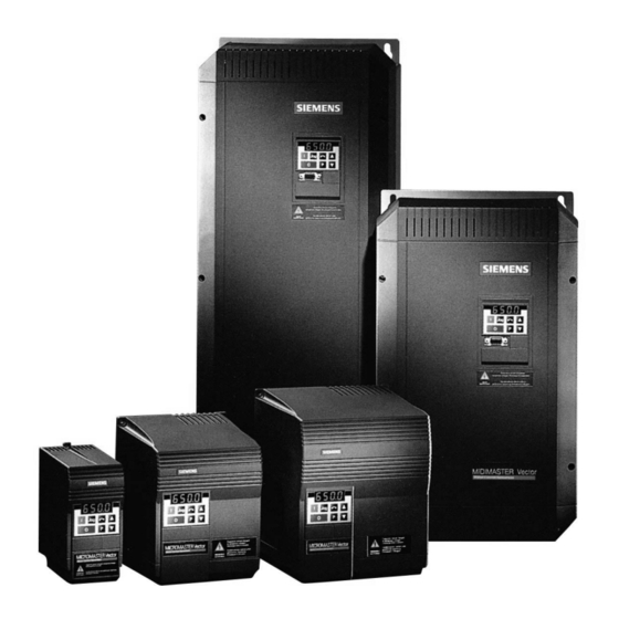
MICROMASTER Vector
MICROMASTER
MIDIMASTER Vector
MIDIMASTER
© Siemens plc 1999
© Siemens plc 1999
Vector
Vector
Operating Instructions
Operating Instructions
Contents
Contents
SAFETY INSTRUCTIONS.............................................4
SAFETY INSTRUCTIONS.............................................4
1. 1. OVERVIEW
OVERVIEW .............................................................6
2. 2. INSTALLATION
INSTALLATION - - MICROMASTER
3. 3. INSTALLATION
INSTALLATION - - MIDIMASTER
4. 4. CONTROLS
CONTROLS AND
5. 5. OPERATING
OPERATING MODES...........................................36
6. 6. SYSTEM
SYSTEM PARAMETERS
PARAMETERS .....................................41
7. 7. FAULT
FAULT AND
AND WARNING
8. 8. SPECIFICATIONS
SPECIFICATIONS ................................................67
9. 9. SUPPLEMENTARY
SUPPLEMENTARY INFORMATION....................73
.............................................................6
MICROMASTER Vector
MIDIMASTER Vector..............
Vector.............. 25
AND BASIC
BASIC OPERATION...............
OPERATION............... 32
MODES...........................................36
.....................................41
WARNING CODES..........................65
CODES..........................65
................................................67
INFORMATION....................73
Vector .........12
.........12
25
32
G85139-H1751-U529-D1
G85139-H1751-U529-D1
4/8/99
4/8/99
Advertisement

Related Manuals for Siemens MICROMASTER Vector Series


Summary of Contents for Siemens MICROMASTER Vector Series
- Page 1 6. 6. SYSTEM SYSTEM PARAMETERS PARAMETERS ........41 ........41 7. 7. FAULT FAULT AND AND WARNING WARNING CODES......65 CODES......65 8. 8. SPECIFICATIONS SPECIFICATIONS ..........67 ..........67 9. 9. SUPPLEMENTARY SUPPLEMENTARY INFORMATION....73 INFORMATION....73 © Siemens plc 1999 © Siemens plc 1999 G85139-H1751-U529-D1 G85139-H1751-U529-D1 4/8/99 4/8/99...
- Page 2 I I f f t t h h e e M M o o t t o o r r D D o o e e s s N N o o t t S S t t a a r r t t U U p p 3 3 8 8 © Siemens plc 1999 © Siemens plc 1999...
- Page 3 U U s s e e r r ' ' s s P P a a r r a a m m e e t t e e r r S S e e t t t t i i n n g g s s 7 7 8 8 © Siemens plc 1999 © Siemens plc 1999...
- Page 4 (rms), for a maximum voltage of 230/460V* when protected by a time voltage of 230/460V* when protected by a time Siemens plc operates a quality management system, which Siemens plc operates a quality management system, which complies with the requirements of ISO 9001.
- Page 5 P006. th P006. If this is not If this is not done, the done, the motor may start inadvertently. motor may start inadvertently. © Siemens plc 1999 © Siemens plc 1999 G85139-H1751-U529-D1 G85139-H1751-U529-D1 4/8/99 4/8/99...
- Page 6 For additional product information such as application examples, part numbers, operation with long cables etc, For additional product information such as application examples, part numbers, operation with long cables etc, please refer to catalog DA64 or to please refer to catalog DA64 or to http://www.con.siemens.co.uk http://www.con.siemens.co.uk Features: Features: •...
- Page 7 Note: The Plastic Material of the case can be degraded by oil or grease. Care should be taken to ensure that ensure that the mounting surface and fixings the mounting surface and fixings are thoroughly degreased before use. are thoroughly degreased before use. © Siemens plc 1999 © Siemens plc 1999 G85139-H1751-U529-D1 G85139-H1751-U529-D1 4/8/99...
- Page 8 © Siemens plc 1999 © Siemens plc 1999 G85139-H1751-U529-D1 G85139-H1751-U529-D1 4/8/99 4/8/99...
- Page 9 Figure 1.2.2: Wiring guidelines to minimise effects of EMI - MICROMASTER Vector Frame Size B Figure 1.2.2: Wiring guidelines to minimise effects of EMI - MICROMASTER Vector Frame Size B © Siemens plc 1999 © Siemens plc 1999 G85139-H1751-U529-D1...
- Page 10 (preparation tim (preparation time e 1 1 hour). hour). • • 2 2 - - 3 3 years years old: old: © Siemens plc 1999 © Siemens plc 1999 G85139-H1751-U529-D1 G85139-H1751-U529-D1 4/8/99 4/8/99 10 10...
- Page 11 25m for screened cable or 25m for screened cable or 50m for unscreened cables. 50m for unscreened cables. © Siemens plc 1999 © Siemens plc 1999 G85139-H1751-U529-D1 G85139-H1751-U529-D1 11 11 4/8/99...
- Page 12 The mains input and motor terminals carry dangerous voltages even if the inverter is not operating. Use insulated screwdrivers on these terminal blocks. Use insulated screwdrivers on these terminal blocks. © Siemens plc 1999 © Siemens plc 1999 G85139-H1751-U529-D1 G85139-H1751-U529-D1...
- Page 13 Frame size A units need two bolts or can be DIN rail mounted. Frame size B and C units require four bolts. Figure 2.1.1: Figure 2.1.1: MICROMASTER Vector MICROMASTER Vector - Frame Size A, B - Frame Size A, B and C and C © Siemens plc 1999 © Siemens plc 1999 G85139-H1751-U529-D1 G85139-H1751-U529-D1 13 13 4/8/99...
- Page 14 * These units also available with built in filter e.g. MMV220/3F filter e.g. MMV220/3F Figure 2.1.2: Figure 2.1.2: Mechanical Installati Mechanical Installation Diagram - MIC on Diagram - MICROMASTER Vector ROMASTER Vector © Siemens plc 1999 © Siemens plc 1999 G85139-H1751-U529-D1 G85139-H1751-U529-D1 4/8/99 4/8/99 14 14...
- Page 15 P P E E THREE PHASE THREE PHASE Figure 2.2.1: Figure 2.2.1: MICROMASTER Vector Connectors MICROMASTER Vector Connectors - Frame Size A - Frame Size A © Siemens plc 1999 © Siemens plc 1999 G85139-H1751-U529-D1 G85139-H1751-U529-D1 15 15 4/8/99 4/8/99...
- Page 16 Frame size C : lift and secure the lift and secure the gland plate and the gland plate and the fan housing to the fan housing to the inverter. inverter. © Siemens plc 1999 © Siemens plc 1999 G85139-H1751-U529-D1 G85139-H1751-U529-D1 4/8/99...
- Page 17 Connect the control leads as shown in Figures unit is mounted and secured to the selected surface. Connect the control leads as shown in Figures 2.2.4 and 2.2.6. 2.2.4 and 2.2.6. © Siemens plc 1999 © Siemens plc 1999 G85139-H1751-U529-D1 G85139-H1751-U529-D1...
- Page 18 Figure 2.2.2 : Figure 2.2.2 : Power and Motor Conn Power and Motor Connectors MICROMASTER Vector ectors MICROMASTER Vector Frame Size B Frame Size B © Siemens plc 1999 © Siemens plc 1999 G85139-H1751-U529-D1 G85139-H1751-U529-D1 4/8/99 4/8/99 18 18...
- Page 19 B- terminals under the inverter. and B- terminals under the inverter. 15. Connect the control leads as shown in Figures 2.2.4 and 2.2.6. Connect the control leads as shown in Figures 2.2.4 and 2.2.6. © Siemens plc 1999 © Siemens plc 1999 G85139-H1751-U529-D1 G85139-H1751-U529-D1...
- Page 20 Figure 2.2.3: Figure 2.2.3: Power Connections Access Power Connections Access Diagram - Frame Size Diagram - Frame Size C C © Siemens plc 1999 © Siemens plc 1999 G85139-H1751-U529-D1 G85139-H1751-U529-D1 4/8/99 4/8/99 20 20...
- Page 21 B- terminals under the inverter. B- terminals under the inverter. 11.Connect the control leads as shown in Figures 2.2.4 and 2.2.6 11.Connect the control leads as shown in Figures 2.2.4 and 2.2.6 © Siemens plc 1999 © Siemens plc 1999 G85139-H1751-U529-D1 G85139-H1751-U529-D1...
- Page 22 T hese switches can only be accessed when the flap in the flap in the the front the the front cover is cover is raised raised (see Figure 2.2.1). (see Figure 2.2.1). © Siemens plc 1999 © Siemens plc 1999 G85139-H1751-U529-D1 G85139-H1751-U529-D1 4/8/99 4/8/99 22 22...
- Page 23 T o enable the motor overload protection trip function, set parameter P087=1 Inverter Control Inverter Control MOTOR MOTOR Terminals Terminals PT C C Figure 2.2.5: Motor Overload PTC Connection. Figure 2.2.5: Motor Overload PTC Connection. © Siemens plc 1999 © Siemens plc 1999 G85139-H1751-U529-D1 G85139-H1751-U529-D1 23 23 4/8/99 4/8/99...
- Page 24 U U , , V V , , W W M M Figure 2.2.6 Figure 2.2.6 Block Diagram Block Diagram - MICROMASTER - MICROMASTER Vector Vector © Siemens plc 1999 © Siemens plc 1999 G85139-H1751-U529-D1 G85139-H1751-U529-D1 4/8/99 4/8/99 24 24...
- Page 25 Figure 3.1.1: Figure 3.1.1: MIDIMASTER Vector - Fram MIDIMASTER Vector - Frame Size 4, 5, e Size 4, 5, 6 and 7 6 and 7 © Siemens plc 1999 © Siemens plc 1999 G85139-H1751-U529-D1 G85139-H1751-U529-D1 25 25 4/8/99...
- Page 26 6 washers M8 Frame Size 7 Frame Size 7 Figure 3.1.2: Figure 3.1.2: Mechanical Installa Mechanical Installation Diagram - M tion Diagram - MIDIMASTER Vector IDIMASTER Vector © Siemens plc 1999 © Siemens plc 1999 G85139-H1751-U529-D1 G85139-H1751-U529-D1 4/8/99 4/8/99 26 26...
- Page 27 MDV5500/3 MDV7500/3 MDV7500/3 7 7 = 500 = 500 x x 1150 1150 x x 595 451 1122 451 1122 Figure: 3.1.2 (continued) Figure: 3.1.2 (continued) © Siemens plc 1999 © Siemens plc 1999 G85139-H1751-U529-D1 G85139-H1751-U529-D1 27 27 4/8/99 4/8/99...
- Page 28 D D C C - - D D C C + + Power and Power and Motor terminals Motor terminals Figure 3.2.1: Figure 3.2.1: MIDIMASTER Vect MIDIMASTER Vector Connectors or Connectors © Siemens plc 1999 © Siemens plc 1999 G85139-H1751-U529-D1 G85139-H1751-U529-D1 4/8/99 4/8/99 28 28...
- Page 29 © Siemens plc 1999 © Siemens plc 1999 G85139-H1751-U529-D1 G85139-H1751-U529-D1...
- Page 30 For protection measures using a PTC see motors require de-rating for continuous operation at low frequencies. For protection measures using a PTC see section 2.2.5. section 2.2.5. © Siemens plc 1999 © Siemens plc 1999 G85139-H1751-U529-D1 G85139-H1751-U529-D1...