Table of Contents
Advertisement
PLEASE RETAIN
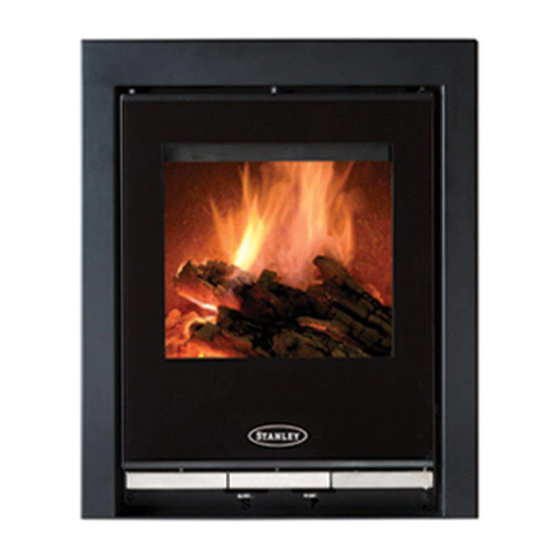
Solis Inset
500 & 900
INSTALLATION AND OPERATING INSTRUCTIONS
This appliance is hot while in operation and retains its heat for a long period of time after use. Children,
aged or infirm persons should be supervised at all times and should not be allowed to touch the hot
working surfaces while in use or until the appliance has thoroughly cooled.
When using the stove in situations where children, aged and/or infirm persons are present a fireguard
must be used to prevent accidental contact with the stove. The fireguard should be
manufactured in accordance with BS 8423:2010.
Advertisement
Table of Contents

Related Manuals for Stanley Solis Inset 500


Summary of Contents for Stanley Solis Inset 500
- Page 1 PLEASE RETAIN Solis Inset 500 & 900 INSTALLATION AND OPERATING INSTRUCTIONS This appliance is hot while in operation and retains its heat for a long period of time after use. Children, aged or infirm persons should be supervised at all times and should not be allowed to touch the hot working surfaces while in use or until the appliance has thoroughly cooled.
-
Page 2: Table Of Contents
Stanley Stove Warranty ........ - Page 3 TABLE OF CONTENTS PAGE NO. 38. Fire Safety ..............22 39.
-
Page 4: Stanley Stove Warranty
CONDITIONS OF WARRANTY Your Stanley Stove is guaranteed against any part that fails (under normal operating conditions) as detailed in the fol- lowing table with timelines specified from the date of installation of the appliance. If the unit is not installed within six months of date of purchase, the warranty will commence six months from the date of purchase. -
Page 5: Installation Checklist
INSTALLATION CHECK LIST Tick Flue System 1. Minimum Flue Height of 4.6 metres (15 feet). 2. Appliance should be connected to a 125mm (5”) flue pipe within a metre and then the flue size increased to a minimum of 150mm (6”) diameter (500 Models). 2A. -
Page 6: Important Operation/ Maintenance Notes
IMPORTANT OPERATION / MAINTENANCE NOTES Now that your Stanley Stove is installed and no doubt you are looking forward to many comforts it will provide, we would like to give you some tips on how to get the best results from your stove. -
Page 7: Installation & Operating Instructions
INSTALLATION & OPERATING INSTRUCTIONS Please note that it is a legal requirement under GENERAL England & Wales Building Regulations that the installation of the stove is either carried out under THE CLEAN AIR ACT 1993 AND SMOKE Local Authority Building Control approval or is CONTROL AREAS installed by a Competent Person registered with a Government... -
Page 8: Flues
Your Solis Inset stove is supplied with the following Fig.1 items: • Ashpan • Glove 2300 • OSA Connection FLUES Flues should be vertical wherever possible and where a bend is necessary, it should not make an angle of more than 45 with the vertical. - Page 9 Fig.5 Ensure that the opening is suitable for fitting of the inset stove (Fig 3 shows 500 Model & Fig 4 shows 900 Model). Ensure that the floor area is level. Remove the top baffle from the firebox by pulling it forward and lifting it up on the RHS to allow the LHS of the baffle to drop into the firebox so that it can be removed through the fire door opening.
-
Page 10: Non Flue Lined Chimney
Fig.9 Connect the extension pipe to the adaptor and seal the joint using the appropriate fire cement. Fit the flue spigot to the extension pipe and seal the joint using the appropriate fire cement. Position the outer casing into the fireplace opening so that the front lip on the casing sits against the front of the opening. -
Page 11: Down Draughts
Fig.10 Fit the flue spigot to the extension pipe and seal the joint using the appropriate fire cement. Position the outer casing into the fireplace opening so that the front lip on the casing sits against the front of the opening. Mark the fixing hole locations in the base of Direction of wind the outer casing and fix in place using a suit-... -
Page 12: External Ducted Air
The effective free area of any vent should be ascer- EXTERNAL DUCTED AIR tained before installation. The effect of any grills should be allowed for when determining the effective Where required the primary air supply can be duct- free area of any vent. ed from outside. -
Page 13: Heat Recovery Ventilation (Hrv)
Fig.11 Note: When Installing outside air pipe adhere to ‘Clearance to Combustible’ Section. 4” ID ALUMINIUM FLEXIBLE DUCT PIPE ENDS TO BE 4” OD CONNECTOR SADDLE COVERED WITH MESH HEAT RECOVERY VENTILATION Model Model Where a stove is to be installed in a dwelling with Heat Recovery Ventilation (HRV) a number of pre- 550mm 550mm... -
Page 14: Technical Data
Fig.13 If the appliance recess is close to any combustible material, it must be adequately protected using a suitable insulation material (See table 1) and config- ured as showing in Fig. 14. TECHNICAL DATA SIL C A 2 5 0 KM MATERIAL DESCRIPTION National technical approval no Z-43.14-117 valid for Approval in Germany... -
Page 15: Floor Protection
The insulation material must be at least 120mm in FLOOR PROTECTION thickness and must be situated at least 100mm away from the rear and sides of the appliance. It is recommended that the appliance is installed on a solid, level, concrete base of non combustible Fig.14 hearth conforming... -
Page 16: Stove Dimensions 500 Model
STOVE DIMENSIONS THREE SIDED FRAME 500 Model Fig.15 FOUR SIDED FRAME... -
Page 17: Stove Dimensions 900 Model
THREE SIDED FRAME 900 Model FOUR SIDED FRAME WARNING: DO NOT OBSTRUCT PRIMARY AIR SUPPLY TO THE STOVE Note: Dimensions stated are in millimetres unless otherwise stated and may be subject to a slight +/- variation. -
Page 18: Commissioning And Handover
RECOMMENDED FUELS COMMISSIONING AND HANDOVER On completion of the installation allow a suitable All fuels should be stored under cover and kept period of time for any fire cement and mortar to dry as dry as possible prior to use. out, when a small fire may be lit and checked to ensure the smoke and fumes are taken from the This appliance has been tested using seasoned... -
Page 19: Technical Data
TECHNICAL DATA SOLIS INSET 500 SOLIS INSET 900 MANUFACTURED MANUFACTURED SMOKELESS FUEL WOOD SMOKELESS FUEL WOOD Nominal Output: (kW) Room 5kW Room 5kW Room 9kW Room 9kW Typical refuelling MSF 1 hour Wood .75 hours MSF 1 hour Wood .75 hours... -
Page 20: Installing The Solid Fuel Kit - 500 & 900 Models
INSTALLING SOLID FUEL KIT - 500 MODEL INSTALLING SOLID FUEL KIT - 900 MODEL IF OPTING TO BURN SOLID FUEL, A SOLID FUEL IF OPTING TO BURN SOLID FUEL, A SOLID FUEL KIT MUST BE INSTALLED. KIT MUST BE INSTALLED. Open the firedoor and remove the ashpan. -
Page 21: Air Controls
AIR CONTROLS Ignition Controlled Burn Fuel Primary Air Secondary Air Primary Air Secondary Air Anthracite/ Fully Open Fully Closed 0-80% Open Fully Closed Smokeless Coal Wood/ Turf Fully Closed Fully Open Fully Closed 0-80% Open Ashes should be placed in a metal or other non- REFUELLING combustible container with a tight fitting lid. -
Page 22: Chimney Cleaning
CHIMNEY CLEANING WARNING NOTE: Properly installed, operated and maintained this The chimney should be cleaned twice annually or if stove will not emit fumes into the dwelling. the stove is not used for a prolonged period during Occasional fumes from the de-ashing and re- the summer period, it should be cleaned prior to fuelling may occur. -
Page 23: Glass Replacement
GLASS REPLACEMENT CO ALARM The fitting of CO Alarms in the same room as the (a) Open the firedoor fully. appliance is a compulsory requirement under cur- (b) Remove the top glass retaining bracket by rent Building Regulations. For ROI an additional CO removing the two fixing screws (see Fig. -
Page 24: Exploded View 500 Model
STANLEY SOLIS INSET 500 EXPLODED VIEW GRATE - 9825001 13. LH BASE BRICK - 093-30-001 DOOR LOCKING SYSTEM - 093-01-060 14. REAR BASE BRICK - 093-30-003 DOOR SUBASSEMBLY - 093-01-010 15. RH BASE BRICK - 093-30-002 DOOR GLASS - 093-01-070 16. -
Page 25: Exploded View 900 Model
STANLEY SOLIS INSET 900 EXPLODED VIEW DOOR GLASS I-G9I - 098-00-012 12. RH SIDE BRICK - 099-09-002 DOOR SUBASSEMBLY I-G9I - 098-01-000 13. LH BASE BRICK - 099-09-004 DOOR LOCKING SYSTEM - 099-03-015 14. RH BASE BRICK - 099-09-004 ASH PAN - 099-00-005 15. - Page 26 NOTES...
- Page 27 NOTES...
- Page 28 Manufactured by Waterford Stanley Ltd., Unit 401-403, IDA Industrial Estate, Cork Road, Waterford, Ireland. Tel: (051) 302300 Fax (051) 302315 Rev: 005 SG 051018...