Table of Contents
Advertisement
PLEASE RETAIN
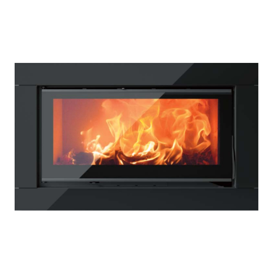
Solis Double Sided
Insert
INSTALLATION AND OPERATING INSTRUCTIONS
This appliance is hot while in operation and retains its heat for a long period of time after use. Children,
aged or infirm persons should be supervised at all times and should not be allowed to touch the hot
working surfaces while in use or until the appliance has thoroughly cooled.
When using the stove in situations where children, aged and/or infirm persons are present a fireguard
must be used to prevent accidental contact with the stove. The fireguard should be manufactured in
accordance with BS 8423:2010.
Advertisement
Table of Contents

Related Manuals for Stanley Solis Double Sided Insert IS80DS


Summary of Contents for Stanley Solis Double Sided Insert IS80DS
- Page 1 PLEASE RETAIN Solis Double Sided Insert INSTALLATION AND OPERATING INSTRUCTIONS This appliance is hot while in operation and retains its heat for a long period of time after use. Children, aged or infirm persons should be supervised at all times and should not be allowed to touch the hot working surfaces while in use or until the appliance has thoroughly cooled.
-
Page 2: Table Of Contents
Stanley Stove Warranty ........ -
Page 3: Stanley Stove Warranty
CONDITIONS OF WARRANTY Your Stanley Stove is guaranteed against any part that fails (under normal operating conditions) as detailed in the fol- lowing table with timelines specified from the date of installation of the appliance. If the unit is not installed within six months of date of purchase, the warranty will commence six months from the date of purchase. -
Page 4: Installation Checklist
INSTALLATION CHECK LIST Tick Flue System 1. Minimum Flue Height of 4.6 metres (15 feet). 2. Appliance should be connected to a minimum of 1.8 metres (6 feet) of 150mm (6”) flue pipe. 3. Any horizontal flue run should not exceed 150mm (6”) 4. -
Page 5: Important Operation/ Maintenance Notes
IMPORTANT OPERATION / MAINTENANCE NOTES Now that your Stanley Woodburning Stove is installed and no doubt you are looking forward to the many com- forts it will provide, we would like to give you some tips on how to get the best results from your stove. -
Page 6: Installation & Operating Instructions
INSTALLATION & OPERATING INSTRUCTIONS Please refer to the current standards, BS EN 15287- GENERAL 1:2007 Design, Installation and Commissioning of When installing, operating and maintaining your chimneys. BS EN 14336:2004: Heating Systems in Solis stove, respect basic standards of fire safety. Buildings. -
Page 7: Fitting Instructions
FITTING INSTRUCTIONS A flue that has proved to be unsatisfactory, particu- larly with regard to down draught should not be used The stove is designed to allow the chimney be for venting this appliance until it has been examined cleaned through the stove. and any faults corrected. -
Page 8: Down Draughts
Step 8 Step 12 Loosen the two screws to remove the fan cover Refit the fire door. plate (see Fig 4). Step 13 Step 9 Repeat steps 7-12 for the second glass frame with Disconnect the fan operation switch from the electri- the blank fan switch cut out blank fitted instead of cal harness. -
Page 9: Ventilation & Combustion Air Requirements
VENTILATION & COMBUSTION AIR REQUIRE- If there is an extraction fan fitted in adjacent rooms MENTS where this appliance is fitted, additional air vents may be required to alleviate the possibility of It is imperative that there is sufficient air supply to spillage of products of combustion from the appli- the stove in order to support correct combustion. -
Page 10: Heat Recovery Ventilation
Fig.8 3” ID ALUMINIUM FLEXIBLE DUCT Note: When Installing outside air pipe adhere to ‘Clearance to Combustible’ Section. PIPE ENDS TO BE 3” OD CONNECTOR SADDLE COVERED WITH MESH HEAT RECOVERY VENTILATION Fig.9 Where a stove is to be installed in a dwelling with Heat Recovery Ventilation (HRV) a number of pre- cautionary measures must be undertaken: Where the product is to be installed with a... -
Page 11: Warm Air Ducting System
Fig.10 POSITIONING OF THE WARM AIR DUCT The following must be adhered to when locating the warm air duct system: The air duct must not touch any combustible materials within 550mm of the back of the appliance. Take care when routing the duct to ensure it is not deformed and restricting the airflow. -
Page 12: Stove Dimensions
STOVE DIMENSIONS IS100 DS MODEL IS80 DS MODEL Note: Dimensions stated are in millimetres unless otherwise stated and may be subject to a slight +/- variation. COMMISSIONING AND HANDOVER tomer on the correct use of the appliance and warn On completion of the installation allow a suitable them to use only Wood. -
Page 13: Air Controls
AIR CONTROLS Fig.13 The Solis Stove has two independent air controls (See Fig. 12) The primary air control lever is the left hand lever located under the fire door. Push right to open and left to close. The secondary air control lever is the lever located above the fire door. -
Page 14: Technical Data
TECHNICAL DATA IS100DS IS80DS 14kW Nominal Output: (kW) 15.3kW Mean Flue Gas Temperature Typical refuelling intervals to obtain nominal outputs: 0.72 hrs 0.72 hrs 0.10% CO at 13% O 0.10% 125kgs Gross Weight 150kgs 150mm (6”) Flue Outlet 150mm (6”) Efficiency 12Pa Flue Draught... -
Page 15: Refuelling
MONTHLY MAINTENANCE REFUELLING Cleaning Stove Flue Pathways Before opening the fire door, open the air controls It is recommended that the flue pathways in the fully as this will help to eliminate any smoke or fly stove are cleaned on a monthly basis (or less ash resident in the combustion chamber. -
Page 16: Periodic Maintenance
GLASS CLEANING Fig.18 The stove glass will self-clean when there is suffi- cient heat generated by the burning fuel i.e. when the unit is operated at the maximum air settings. If a build-up of creosote occurs on the glass it may be due to low draft conditions, poor quality fuel or oper- ating the stove at the minimum air settings for long periods of time. -
Page 17: Fire Safety
FIRE SAFETY CO ALARM The fitting of CO Alarms in the same room as the To provide reasonable fire safety, the following appliance is a compulsory requirement under cur- should be given serious consideration. rent Building Regulations. For ROI an additional CO Alarm must be fitted either inside each bedroom or 1. -
Page 18: Electrical Diagram
ELECTRICAL DIAGRAM... -
Page 19: Exploded View
IS100DS/IS80DS - EXPLODED VIEW PART CODE PART CODE DESCRIPTION DESCRIPTION I100DS I80DS I100DS I80DS PRIMARY BAFFLE DEFMETKR100DC DEFMETKR80DC DOOR ROPE SEAL CORD8 SECONDARY DEFSUPKR100DC DEFSUPKR80DC DOOR HANDLE MANETA BAFFLE DOOR HANDLE FIXING KITMAN BAFFLE FIXING SUJLATKR100DC SUJLATKR80DC SWITCH BLANK 20ELC1 BRACKETS A1819 SIDE BRICKS... - Page 20 Manufactured by Waterford Stanley Ltd., Unit 401-403, IDA Industrial Estate, Cork Road, Waterford, Ireland. Tel: (051) 302300 Fax (051) 302315 N00777AXX Rev: 001 SG 210518...