
Related Manuals for Stanley Oisin Oil MK II


Summary of Contents for Stanley Oisin Oil MK II
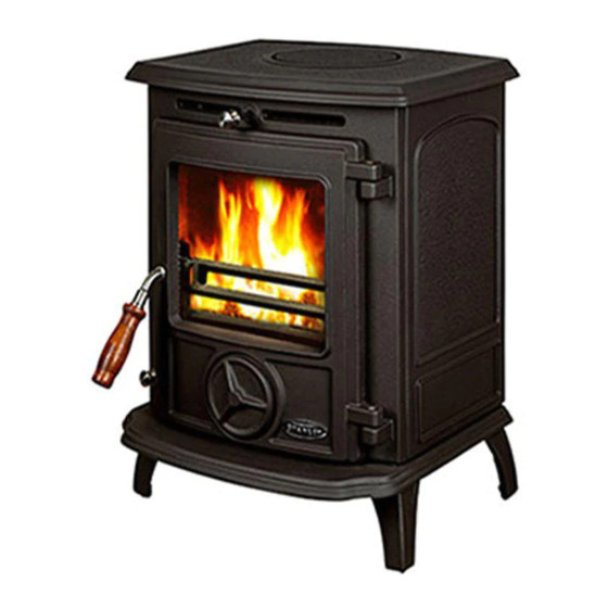
- Page 1 Oisin Oil MK II Stove INSTALLATION AND OPERATION INSTRUCTIONS To ensure safety, satisfaction and reliable service this stove should be installed by a suitably qualified and competent person. To be left with end user.
-
Page 2: Table Of Contents
TABLE OF CONTENTS Introduction ............3 Technical Data. -
Page 3: Introduction
Installation should be carried out in a well ventilated area. Any alterations to this appliance that are not approved in writing by Waterford Stanley will render the guarantee void. This appliance is hot while in operation and retains its heat for a long period of time after use. Children, aged or infirm persons should be supervised at all times and should not be allowed to touch the hot working surfaces while in use or until the appliance has thoroughly cooled. -
Page 4: Stove Dimensions
STOVE DIMENSIONS NOTE: Dimensions stated below may be subject STOVE WEIGHT = 160 lbs / 73 kilos to a slight +/- variation. DIMENSIONS METRIC (mm) IMPERIAL (inch) 3 /4 3 /4 1 /4 3 /4 1 /2 NOTE: ALL INSTALLATION WORK MUST BE CARRIED OUT BY A TRAINED AND COMPE- TENT PERSON. -
Page 5: Installation
INSTALLATION The installation shall comply with the following: B.S. 5410 Part 1 Oil Installations The Building Regulations: Part J England, Wales. Part F Section III Scotland Part L Northern Ireland Part J Ireland The Control of Pollution (Oil) Regulations: B.S. 7671: Requirements for Electrical Regulations Safety Document 635: The Electricity at Work Regulations. -
Page 6: Fuel Supply/Installation
FUEL SUPPLY / INSTALLATION Exposed lengths of oil supply pipe must be properly OIL STORAGE TANKS: supported by purpose made clips securely fixed in Oil storage tanks made of steel and all connecting place. Metal clips formed so as to hold the pipe on equipment (e.g. -
Page 7: Clearance To Combustibles
These requirements are in accordance with the fol- Fig.6 lowing relevant sections of BS 5410: Part 1 O.F.S. A105 Oil Stove Standard. The Building Regulations for Scotland, Ireland, Northern Ireland, England & Wales. NOTE: Fuel to the appliance should be gravity fed only. -
Page 8: Flue Systems
BLOCKED CHIMNEYS ARE DANGEROUS. THE FLUE MUST BE INSPECTED AT LEAST ANNUAL- LY AND CLEANED WHEN NECESSARY. STANLEY CAST IRON PIPES AND BENDS ARE If connecting to an existing oversized chimney it is HIGHLY RECOMMENDED FOR INTERIOR USE. necessary to line the flue using 125mm - 5” rigid of flexible preferably rigid stainless steel class 1 or USE OF EXISTING FLUES &... -
Page 9: Flue Liner
FLUE LINERS FACTORY MADE INSULATED CHIMNEYS Chimneys lined with salt glazed earthenware pipes Factory made insulated chimney systems should be are acceptable if the pipes comply with B.S. 1181 constructed and tested to meet the relevant stan- and must be 125mm (5”) diameter. When using an dards and recommendations given in B.S. -
Page 10: Down Draughts
DOWN DRAUGHTS The combustion air must be provided in the room containing the appliance through purpose made However well designed, constructed and positioned, non-closable openings having a total free area of 29 the satisfactory performance of the flue can be adversely affected by down draught caused by All materials used in the manufacture of air vents nearby hills, adjacent tall buildings or trees. -
Page 11: Barometric Damper
Fit the flue adaptor to the back casting using Fig.17 the gasket provided. Figs. 13 & 14 shows connection to top outlet while figs.15 & 15a shows connection to back outlet. Fig.14 Fig.13 Position the stove in its final location. Refer to sections D,E,F,G,H, and I to ensure that all requirements have been met. - Page 12 Fig.22 Burner Set-Up Ensure that the stove is plugged out. Using a spirit level, ensure the stove is level in all directions. Adjust the levelling screws on the stove legs if necessary. See fig. 18. Check that the oil control valve is level in all directions.
- Page 13 Once the stove has stabilised at setting 6, soaked up with an absorbent paper and the open the spin valve until an acceptable flame filling process (steps 7 & 8) should be pattern is achieved. Flames should be repeated. mainly blue with some yellow tips and Fig.24 should mainly emanate from the front and sides of the burner.
-
Page 14: Burner Assembly
Fig.31 BURNER ASSEMBLY With the burner base level and the correct depth of oil in the burner rings, the following steps should be followed for assembling the burner. Replace the wicks in the burner rings as per Fig. 29 Ensure that the cut-outs in the wicks line up with the fuel ports between the cen tral reservoir and inner ring and between the inner and outer rings. -
Page 15: Flame Pattern
If after adjusting the spin valve, there are still exces- Fig.34 sively long yellow flames striking the top baffle, con- sult the Fault Finding section of this manual. STOVE OPERATION Lighting the Stove STOVE IN START/MAXIMUM STOVE IN OFF POSITION POSITION Fig.38 Fig.37... -
Page 16: Replacing Electrical Parts
THE STOVE MUST BE COLD BEFORE Fig.41 S E RVICING. ALLOW 3-4 HOURS FOR THE STOVE TO COOL. Ensure that the electrical supply to the stove is turned off and that the control knob is turned to the off position (0). (See Fig.38). Inspect the inside of the door and clean the glass if required. -
Page 17: Control Valve Rating
Disassemble the transformer cover to Fig.44 access the transformer and the connector block. The wiring for the faulty component can be disconnected and the faulty compo- nent replaced. Reassemble the transformer cover and re- fit the cover to the carrier bracket. Refit the mate ‘n’... -
Page 18: Wiring Diagram
WIRING DIAGRAM Fig.47... -
Page 19: Fault Finding
Ensure that no coals have fallen against the door Poor door seal Replace door seal Fuel input rate too high Check fuel input rates, adjust if necessary Waterford Stanley Ltd., Bilberry, Waterford, Ireland. Tel: 051-302300 Fax: 051-302399 DP 021105 Rev:003...