Table of Contents
Advertisement
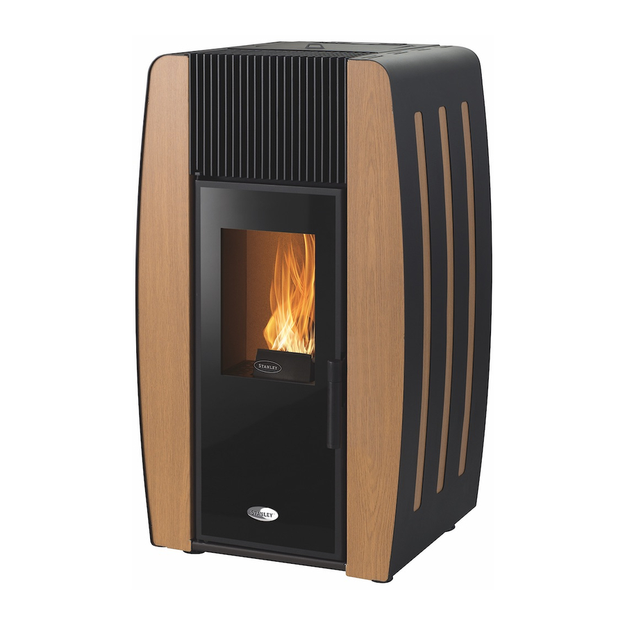
K100 & K300
Wood Pellet Stoves
INSTALLATION AND OPERATING INSTRUCTIONS
This appliance is hot while in operation and retains its heat for a long period of time after use.
Children, aged or infirm persons should be supervised at all times and should not be allowed to touch
the hot working surfaces while in use or until the appliance has thoroughly cooled.
When using the stove in situations where children, aged and/or infirm persons are present a fireguard
must be used to prevent accidental contact with the stove. The fireguard should be manufactured in
BS 8423:2002.
accordance with
Advertisement
Table of Contents

Related Manuals for Stanley K100


Summary of Contents for Stanley K100
- Page 1 K100 & K300 Wood Pellet Stoves INSTALLATION AND OPERATING INSTRUCTIONS This appliance is hot while in operation and retains its heat for a long period of time after use. Children, aged or infirm persons should be supervised at all times and should not be allowed to touch the hot working surfaces while in use or until the appliance has thoroughly cooled.
-
Page 2: Table Of Contents
Stanley Pellet Stove Warranty ........ -
Page 3: Setting The Language
CONDITIONS OF WARRANTY Your Stanley pellet stove is guaranteed against any part that fails (under normal operating conditions) as detailed in the following table with timelines specified from the date of installation of the appliance. If the unit is not installed within six months of date of purchase, the warranty will commence six months from the date of purchase. -
Page 4: Important Operation/ Maintenance Notes
Do not burn fuel with a high moisture content, ie damp pellets. Do not tamper with the safety devices or adjustment features without prior authorization from Waterford Stanley During the first firings it is recommended to ventilate the room as an unpleasant (not toxic) odour may be emit- ted as the paint is completing curement. -
Page 5: Installation Checklist
INSTALLATION CHECKLIST Flue System 1. Minimum Flue Height of 2 metres. 2. Tee piece fitted at base of flue. 3. Appliance should be connected using an 80mm connecting flue pipe, increasing to 125mm within 1.5 metres of the appliance 4. Horizontal run of connecting pipe must not exceed 600mm. 5. -
Page 6: Technical Specifications
Technical Specifications Parameters K100 K300 Units Height Width Depth Weight Diameter of the fume discharge pipe Hopper capacity Maximum heating capacity m³ Maximum heat output Minimum heat output Minimum fuel consumption kg / h Maximum fuel consumption kg / h Rated electrical current Electric power at start-up (<10 min.) - Page 7 K300 K100...
-
Page 8: Unpacking
Contents The package of this unit contains: Free Standing Pellet Stove K100, or K300 Instruction manual Power cable; Infrared remote control; Cleaning bar handle; Covers according to selected model. Unpacking the Unit To unpack the equipment, you must first Installation Requirements remove the retractable bag that surrounds the Location, Suitable area to be heated. -
Page 9: Flue/ Chimney Installation
45 authorised Stanley service agent. degrees. The flue termination point/outlet must be above roof level and in accordance with building regulations part J. -
Page 10: Clearance To Combustibles
Clearances to combustibles In the event that the product is installed in a non combustible recess, clearances for ser- A clearance to combustibles of 100cm must be vicing,must be provided, 200mm to the rear maintained above the stove see Fig 5 and 300mm to the sides. -
Page 11: Using The Pellet Stove
Using the Pellet Stove Before starting up the unit, please check the following: Ensure the unit is properly connected to the power mains using the 230V AC power cable. Fig. 8 Remote Control The infrared remote control allows the user to turn the unit ON and OFF, control the fan air- flow and increase or decrease the unit's power level. -
Page 12: Control And Display Panel
Control and Display Panel Button Function Mode/ Esc Toggle between manual and automatic mode / escape or exit menus . Menu / OK when flashing Access menus / ok -accept value On / OFF Start unit when it is off , stop unit when it is on, Resets error messages Minus sign “-”... -
Page 13: Setting Time And Date
Setting the Date and Time Press "+" to scroll to the next menu. The “Day number” is displayed. This is the date / day of Setting the date: the month. press the Menu key twice until “Day and Time is displayed. To set the “Date”... -
Page 14: Setting The Programmer
Press “set”; the display starts to flash. Press Setting the Programmer. the “+” or “-“ key to select the desired pro- The unit is equipped with a timer that allows gramme and then press “ok” to confirm. Press the unit to be turned on or off at specified the "+"... - Page 15 To set the operating power level (1 to 5) of Programme P1, press “Set”. The display starts to flash. Press the “+” or “-" key to select the desired power level (1 to 5), and then “Ok” to confirm. Press the "+" key to go to the "Days" menu.
-
Page 16: User Information
User Information Once the pre-set time is elapsed, the unit To access the user information. shuts down. At the start of the Shutdown press “set” twice and then press “+” until phase, another timer for a different pre-set “ User Info is displayed” period of time is triggered (Start-up delay time: press set to acess the “User info”... -
Page 17: Combustion Settings
Combustion settings. Shut down. This allows for adjustment of the “pellet” quan- To turn off the pellet stove is carried out by tity and the “air flow” pressing the ON / OFF button for 3 seconds. The display will show “shut down” until full Pellet completion of this phase. - Page 18 Assembly Instruction for Installing the control panel, side panels , hopper cover and grill. Note Installing the Casings on K100. When installing the display handle it with care Before installing the casings you should check because there is a cable from the central unit immediately whether the packing is complete of the stove connected to it.
- Page 19 Secure the side panels to the back of the unit using 10 screws from the kit, as shown in Fig. 15 Figure 18. Fig. 16 Fig. 18 The cover is equipped with four guide pins (1) in the bottom to ensure its proper placement. These guide pins must be fitted onto the springs in located in the structure.
- Page 20 Fit the top plate as shown in figure 21. Installing the Casings on K300. To ensure that the top is properly seated, it Before installing the casings you should check contains four pins on the bottom that should fit immediately whether the packing is complete the springs in the frame.
- Page 21 Fasten the upper part of the grill with two self tapping screws location C, fixed directly to the Fig. 26 cover previously placed. Then fix with M5x12 screws at locations marked A and fix with M5x12 screws and M5 nuts at locations marked B, see figure 24.
-
Page 22: Maintenance / Glass Cleaning
Fig. 31 The reservoir will hold approx 15 kg on the K100 with the K300 holding approx 18kg to fill the hopper carefully cut the corner of the bag so the pellets can be poured into the hopper Fig. -
Page 23: Weekly Maintenance
Ash pan removal Weekly Maintenance/Cleaning the flueways. To perform this maintenance, pull the cleaning bar from the heat exchanger see fig 34, then open the door (b), vacuum the ash and clean the burner (c). Fig. 34 Fig. 36 Fig. 37 Grate removal Fig. -
Page 24: Additional Cleaning
Additional cleaning should be performed for every 600-800 kg of pellets burned. Remove the side covers, to access the side lids of the combustion chamber. To clean the interior of the unit, remove the screws Removal of cleaning access panels K100 Fig. 40 Fig. 42... - Page 25 If you noticed that the flue gas extraction is not Following removal of the panels . Using a 20- effective, we recommend cleaning the interior 25mm wide 80cm long steel brush,thoroughly of the extractor with a vacuum cleaner, as clean the channels and vacuum clean the shown in figure 46.
-
Page 26: Troubleshooting
Note A “service” warning on the display (mainte- nance due) indicates that the unit has exceed- ed 2100 operating hours. In this case, the client must perform the unit's maintenance pro- cedure (following the instruction on the Technical Manual). Once this procedure is completed the hour meter may be reset, to clear the waning message. - Page 27 Troubleshooting guide Note When triggered, all the alarms below cause the machine to shutdown. The alarm must be reset and the unit restarted. To reset the unit, press the “On/Off” button for 10 seconds until the alarm sounds.
-
Page 30: Electrical Diagrams
Electrical diagrams... -
Page 31: Ignition Logic Flow Diagram
Ignition process... -
Page 32: Shut Down Logic Flow Diagram
Shut down process Fixed timer program schedules Manufactured by Waterford Stanley Ltd., Unit 401-403, IDA Industrial Estate, Cork Road, Waterford, Ireland. Tel: (051) 302300 NH 181218 Rev 001 Item No: N00832AXX...