Table of Contents
Advertisement
PLEASE RETAIN
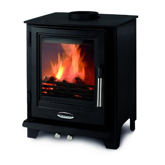
Solis F650 Style
Solid Fuel Stove
INSTALLATION AND OPERATING INSTRUCTIONS
This appliance is hot while in operation and retains its heat for a long period of time after use. Children,
aged or infirm persons should be supervised at all times and should not be allowed to touch the hot
working surfaces while in use or until the appliance has thoroughly cooled.
When using the boiler stove in situations where children, aged and/or infirm persons are present a fire-
guard must be used to prevent accidental contact with the stove.
The fireguard should be
manufactured in accordance with BS 8423:2010.
Advertisement
Table of Contents

Related Manuals for Stanley Solis F650 Style


Summary of Contents for Stanley Solis F650 Style
- Page 1 PLEASE RETAIN Solis F650 Style Solid Fuel Stove INSTALLATION AND OPERATING INSTRUCTIONS This appliance is hot while in operation and retains its heat for a long period of time after use. Children, aged or infirm persons should be supervised at all times and should not be allowed to touch the hot working surfaces while in use or until the appliance has thoroughly cooled.
-
Page 2: Table Of Contents
Stanley Solid Fuel Stove Warranty ........ -
Page 3: Stanley Solid Fuel Stove Warranty
Department. All warranty claims must be reported to the Waterford Stanley Service Department and must be submitted with the prod- uct serial number (located on the front casting), date of purchase, proof of purchase (if requested) and details of the specific nature of the problem. -
Page 4: Installation Checklist
INSTALLATION CHECK LIST Tick Flue System 1. Minimum Flue Height of 4.6 metres (15 feet). 2. Appliance should be connected to a 125mm (5”) flue pipe within a metre and then the flue size increased to a minimum of 150mm (6”) diameter. 3. -
Page 5: Important Operation/ Maintenance Notes
IMPORTANT OPERATION / MAINTENANCE NOTES Now that your Stanley Solid Fuel Stove is installed and no doubt you are looking forward to the many comforts it will provide, we would like to give you some tips on how to get the best results from your stove. -
Page 6: Installation & Operating Instructions
1:2007 Design, Installation and Commissioning of When installing, operating and maintaining your chimneys. BS EN 14336:2004: Heating Systems in Stanley Stove respect basic standards of fire safety. Buildings. Installation & Commissioning of Water Read these instructions carefully before commenc- Based Heating Systems. -
Page 7: Flue Exit (Top And Rear)
All register plates, restrictor plates, damper etc., The stove comes partially configured for top outlet which could obstruct the flue at a future date should and requires the flue spigot (supplied in the firebox) be removed before connecting this appliance. to be fitted to the top outlet flue connection as shown in Fig 3 using the nuts &... -
Page 8: Down Draughts
VENTILATION & COMBUSTION AIR REQUIRE- Fig.4 MENTS It is imperative that there is sufficient air supply to the stove in order to support correct combustion. The air supply to this appliance must comply with current Building Regulations Part J, Heat Providing Appliances. -
Page 9: External Ducted Air
If there is an extraction fan fitted in adjacent rooms EXTERNAL DUCTED AIR where this appliance is fitted, additional air vents may be required to alleviate the possibility of An outside air kit which will allow for the air supply spillage of products of combustion from the appli- for the stove to be ducted from outside and is avail- able to order for connection to the stove. -
Page 10: Heat Recovery Ventilation (Hrv)
LOCATION There are several conditions to be considered in FLOOR PROTECTION selecting a location for your Stanley Stove. When installing this heater on a combustible floor, a a. Position in the area to be heated, central floor protector consisting of a layer of non com- locations are usually best. -
Page 11: Stove Dimensions
STOVE DIMENSIONS Fig.9 WARNING: DO NOT OBSTRUCT PRIMARY AIR SUPPLY TO THE STOVE Note: Dimensions stated are in millimetres unless otherwise stated and may be subject to a slight +/- variation. COMMISSIONING AND HANDOVER OPERATION On completion of the installation allow a suitable period of time for any fire cement and mortar to dry Check that all dampers and catches are operating out, when a small fire may be lit and checked to... -
Page 12: Recommended Fuels
This stove has obtained HETAS Ltd approval for RECOMMENDED FUELS burning natural and manufactured smokeless fuels All fuels should be stored under cover and kept only as detailed in recommended fuels below. as dry as possible prior to use. HETAS Approval does not cover the use of other fuels either alone or mixed with the recommended This appliance has been tested using seasoned fuels listed, nor does it cover instructions for the use... -
Page 13: Lighting The Stove
LIGHTING THE STOVE SLOW BURNING NOTE: When operating the stove, it is recommend- Slow burning will cause the window glass to blacken ed to use the Glove provided to open the and should not be used for a long period. It should fire door as the door handle will become only be done after the fire has been established and hot. -
Page 14: Monthly Maintenance
PERIODIC MAINTENANCE MONTHLY MAINTENANCE Adjusting the Door Catch Cleaning Stove Flue Pathways Over time, the fire door latch can loosen due to the It is recommended that the flue pathways in the continual compression and hardening of the rope stove are cleaned on a monthly basis (or less seal between the door and the front casting. -
Page 15: Fire Safety
GLASS REPLACEMENT WARNING NOTE: Properly installed, operated and maintained this Open the door fully. stove will not emit fumes into the dwelling. Remove the four fixing screws and clips Occasional fumes from the de-ashing and re- (see Fig 14). fuelling may occur. However, persistent fume emis- Clean the glass recess in the door. -
Page 16: Exploded View
- A5 AIR CONTROL ROD 18. FIRE FENCE - A5 RET BAR CAST 19. GRATE - W5 CAST GRATE LR Manufactured for Waterford Stanley Ltd., Unit 401-403, IDA Industrial Estate, Cork Road, Waterford, Ireland. Tel: (051) 302300 Fax (051) 302315 N00812AXX Rev:001 SG 130718...