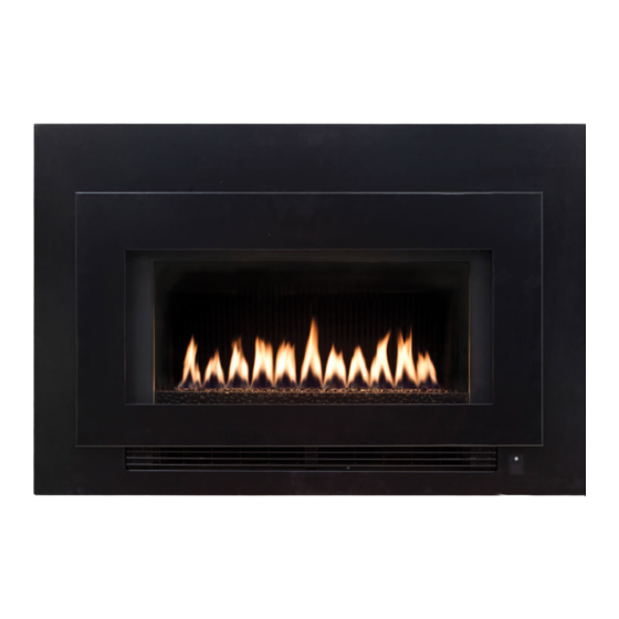
Rinnai Arriva 752 Installation Manual
Hide thumbs
Also See for Arriva 752:
- Operation manual (20 pages) ,
- Installation manual (20 pages) ,
- Operation manual (20 pages)
Table of Contents
Advertisement
Quick Links
Download this manual
See also:
Operating Manual
Advertisement
Table of Contents

Related Manuals for Rinnai Arriva 752


Summary of Contents for Rinnai Arriva 752
- Page 1 Installation guide Arriva 752 Models: RHFE752ETRN/RHFE752ETRL...
- Page 2 Important Appliance must be installed with a Rinnai approved flue system. This appliance shall be installed in accordance with: - Manufacturer’s installation instructions - AS/NZS 5601 Gas Installations Installation, servicing and repair shall be carried out only by authorised personnel.
-
Page 3: Table Of Contents
Setting the air guide vanes ......... 14 Panel installation ............ 15 Test operation and lighting sequence ..... 16 Wiring diagram ............17 Arriva flueing ............18 Flueing options ............19 Arriva flue components ........20 Arriva 752 - fitting the condensate ....22... -
Page 4: Specification
Thermostat control, temperature range 16-26 °C. unit. Weight: 70 kg 1050 Two piece frame: A = 98, B = 20 Single frame: A = 90, B = 12 Dimensions are in mm. 4 | Arriva 752 Installation Guide: 12218-F 06-18... -
Page 5: Clearances
A hearth is not necessary but can be used for decorative purposes or protection of sensitive flooring if required. A hearth must not obscure the front of the fire or obstruct the fire in any way (including the frame around the fire). Arriva 752 Installation Guide: 12218-F 06-18 | 5... -
Page 6: Tv Installation
TV is not to be installed 400 mm minimum above a fireplace. Rinnai does not accept any responsibility for damage to a TV resulting from the use of this information. 6 | Arriva 752 Installation Guide: 12218-F 06-18... -
Page 7: Framing Dimensions
Framing dimensions The main points governing location are flueing and warm air distribution. The Rinnai Arriva has an integrated zero clearance box that isolates the appliance from combustible materials. This means it can be installed directly into a decorative fireplace constructed from materials such as wood or plaster. -
Page 8: Gas Connection
The power cord passes through a slot in the lower right hand side of the appliance. Rinnai recommend the heater be plugged into a 230 V, 10 A earthed power point. The power point must not be above the heater. Alternatively the appliance can be direct wired if the power supply is to be concealed. -
Page 9: Flue Transition
The enclosure depth for a down and out installation is 500 mm to allow the flue pipe to clear the base of the appliance. Appliance needs to be down rated—refer data plate. Arriva 752 Installation Guide: 12218-F 06-18 | 9... -
Page 10: Arriva 752 Installation
Air inlet hose and connect using the clamp. Telescopic horiz. flue pipe e. Replace the flue access panel. Transition Clamp Flue slide stopper (ASPDFK & ASPKIT03) Telescopic vertical flue pipe 10 | Arriva 752 Installation Guide: 12218-F 06-18... - Page 11 Secure the heater, using appropriate fixings, through the four appliance mounting points—two upper and two lower (on each side of the appliance). Appliance mounting points Check all connections Check all connections are properly engaged and are inserted beyond the o-ring seal. Arriva 752 Installation Guide: 12218-F 06-18 | 11...
-
Page 12: Installing The Burn Media
Installing the burn media Only the burn media designed for the Arriva 752 (black stones, and white quartz) can be used. NEVER install burn media from other fires, or mix burn media as this can create a dangerous installation. Please read these instructions carefully as incorrect placement of the stones or quartz is not covered under warranty. -
Page 13: Commissioning
The commissioning sheet is located in a plastic pouch behind the removable access panel on the combustion chamber glass panel, as shown below. Follow the commissioning instructions, and ensure correct operation of the appliance. Commissioning sheet position Arriva 752 Installation Guide: 12218-F 06-18 | 13... -
Page 14: Setting The Air Guide Vanes
- Do not attempt to adjust the air flow direction while the appliance is operating or still hot as this could result in a burn injury Air guide vanes Air guide vanes can be adjusted to the left or right 14 | Arriva 752 Installation Guide: 12218-F 06-18... -
Page 15: Panel Installation
Panel installation The fascia of the Arriva 752 is fully assembled and packaged in a separate carton. Always inspect the glass for any chip or obvious sign of damage before installation. Care is required when handling the front fascia—no sudden impact or excess force should be applied. -
Page 16: Test Operation And Lighting Sequence
If the appliance cannot be made to perform correctly please contact Rinnai. Installation checklist and customer handover Complete the installation checklist in the customer operation guide, and make sure you leave the guide with the customer. -
Page 17: Wiring Diagram
6 5 4 4 3 2 1 3 2 1 bl w y bk pl gy or y or bk bk y bk br bl w 8 6 3 4 1 Arriva 752 Installation Guide: 12218-F 06-18 | 17... -
Page 18: Arriva Flueing
Shared flues Gas appliances must not be connected to a chimney or flue serving a separate fuel burning appliance. Self-supporting flue using straps within the cavity 18 | Arriva 752 Installation Guide: 12218-F 06-18... -
Page 19: Flueing Options
1 m. For example, if an installation has three 90° bends, the maximum length can be 5.5 m. The adaption flue (ASPKIT03) is counted as one 90° bend. For lowest cost, optimal performance, ease of installation and servicing, Rinnai recommend direct flued installations are considered before all other options. -
Page 20: Arriva Flue Components
65 mm 115 mm Long End Condensate Short End tray Condensate drain hose Barb (top) Condensate Wire Tie Tube Ø 50 90° Bend Ø 75 20 | Arriva 752 Installation Guide: 12218-F 06-18... - Page 21 (4350), and spacer flueing. (4351). Ø 50 mm 35 mm Female end (do not cut) Male end (can cut), protrudes approx. 25 mm from bottom of pipe Ø 75-80 mm Arriva 752 Installation Guide: 12218-F 06-18 | 21...
-
Page 22: Arriva 752 - Fitting The Condensate
Detailed instructions are provided with the ASPKIT03 and the ESCONDK, instructions part number 10591. R1970 Condensate tray kit that comes Condensate tray fitted inside unit. with the ASPKIT03 and the ESCONDK Tray and hose in unit Hose fitted 22 | Arriva 752 Installation Guide: 12218-F 06-18... - Page 24 Experience our innovation Rinnai.co.nz 0800 746 624 Arriva 752 Installation Guide: 12218-F 06-18 http://www.youtube.com/rinnainz...