
Related Manuals for Furuno CH-500


Summary of Contents for Furuno CH-500
- Page 1 OPERATOR'S MANUAL SEARCHLIGHT SONAR/ DUAL-FREQUENCY SEARCHLIGHT SONAR CH-500 CH-600 Model www.furuno.com...
- Page 2 ・FURUNO Authorized Distributor/Dealer 9-52 Ashihara-cho, Nishinomiya, 662-8580, JAPAN A : MAR 2017 Printed in Japan All rights reserved. D : APR . 06, 2018 Pub. No. OME-13540-D ( TAYA ) CH-500/CH-600 0 0 0 1 9 2 2 0 8 1 3...
- Page 3 How to discard a used battery Some FURUNO products have a battery(ies). To see if your product has a battery, see the chapter on Maintenance. Follow the instructions below if a battery is used. Tape the + and - terminals of bat- tery before disposal to prevent fire, heat generation caused by short circuit.
- Page 4 If the equipment is giving off smoke abnormally or giving off strange or fire, immediately turn off the power noises, immediately turn off the at the switchboard. WARNING power at the switchboard and contact a FURUNO service technician. Fire or electrical shock can result.
- Page 5 Keep the sonar oil out of reach of Do not remove the label(s). If a label is missing or • children. damaged, contact a FURUNO agent or dealer about Emergency procedures replacement. If the sonar oil enters eyes, flush with •...
-
Page 6: Table Of Contents
TABLE OF CONTENTS FOREWORD ........................vii SYSTEM CONFIGURATION ..................ix OPERATIONAL OVERVIEW ................1-1 1.1 Description of Controls....................1-1 1.1.1 Control Units ....................1-1 1.1.2 Remote Control Unit CH-256 (option) ............1-2 1.2 How to Turn the Power On/Off...................1-2 1.2.1 How to turn the power on ................1-2 1.2.2 How to turn the power off ................1-3 1.3 How to Raise/Lower the Transducer................1-3... - Page 7 TABLE OF CONTENTS HORIZONTAL MODE ....................2-1 2.1 Operational Overview ....................2-1 2.2 Horizontal Menu Overview ..................2-2 2.3 Mix Display (CH-600 only)..................2-3 2.4 Typical Horizontal Mode .................... 2-5 2.5 Full-circle A-Scope Mode ..................2-6 2.6 Horizontal Mode (Zoomed)..................2-7 2.7 Horizontal + History Mode ..................
- Page 8 TABLE OF CONTENTS 5.12 How to Adjust the Speaker Settings.................5-11 5.12.1 How to adjust the speaker frequency............5-11 5.12.2 How to select the speaker bandwidth ............5-11 5.12.3 How to set the harmonic pattern ..............5-12 5.12.4 How to filter for doppler shift ................5-12 5.13 How to Use the Simulation Mode................5-13 5.14 How to Restore the System Menu to Default Settings ..........5-14 5.15 System Settings menu .....................5-15...
-
Page 9: Foreword
Please carefully read and follow the recommended procedures for operation and maintenance. Features The CH-500 is a searchlight sonar and the CH-600 is a dual-frequency searchlight sonar. These systems consist of a display unit, a control unit, a transceiver unit and a hull unit. The main features are: •... - Page 10 FOREWORD • Change the TX cycle. The CH-500 has the third priority and the CH-600 has the second priority. Standards used in this manual • The keys and controls on the Control Units (CH-502, CH-602, CH-256) are shown in bold face;...
-
Page 11: System Configuration
SYSTEM CONFIGURATION Rectifier Unit Remote Display Unit Transceiver Unit RU-1746B-2 Controller MU-121C CH-503 CH-256 100/110/220/ 230 VAC, 1ø, 50/60 Hz 12-24 VDC Control Unit CH-502 CH-602 Loudspeaker CA-151S-ASSY External monitor* Navigational Equipment/ Remote (MU-150HD or Fish Finder/ Controller market equivalent) Heading Sensor/ CH-256 Current Indicator/... - Page 12 SYSTEM CONFIGURATION This page is intentionally left blank.
-
Page 13: Operational Overview
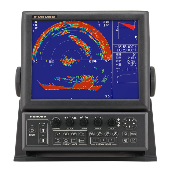
OPERATIONAL OVERVIEW Description of Controls 1.1.1 Control Units Control Unit CH-502 (for CH-500) Control Unit CH-602 (for CH-600) Control name Description POWER key Turns the power on/off. See section 1.2. XDR up/down keys Raises/lowers the transducer. See section 1.3. GAIN (PUSH) knob Adjusts receiver sensitivity (gain). -
Page 14: Remote Control Unit Ch-256 (Option)
1. OPERATIONAL OVERVIEW Control name Description Scan/track keys • Toggle between full-range scan (360°) and half-range scan (168°). See section 1.13. • Reverse the scanning direction. See section 1.11.1. • Change the train speed. See section 2.11. • Activate/deactivate the tracking function. See section 1.16. Function keys Performs custom operations or functions. -
Page 15: How To Turn The Power Off
1. OPERATIONAL OVERVIEW 1.2.2 How to turn the power off It is recommended to retract the transducer before you turn the power off. Also, to avoid excessive stress on the hull unit’s shaft, reduce your speed to below 15 knots before retracting the transducer. -
Page 16: How To Raise The Transducer
1. OPERATIONAL OVERVIEW 1.3.2 How to raise the transducer To raise the transducer, do the following: 1. Press the XDR up key ( ) to raise the transducer. The lamp above the key blinks to indicate that the transducer is being raised. When the transducer is com- pletely retracted, the lamp lights steadily. -
Page 17: How To Select A Display Mode
1. OPERATIONAL OVERVIEW How to Select a Display Mode The CH-500/CH-600 has multiple display modes, all available at the push of a button. The figure below shows examples of the display mode buttons and their use. To select a display mode, press the appropriate button. - Page 18 1. OPERATIONAL OVERVIEW Selecting a Display Mode (only for the CH-600) The following displays are available with the dual-frequency transducer. Display mode example Display mode example DUAL-FREQ HORIZONTAL DUAL-FREQ. HORIZ. EXPANSION 360° dual-freq. display of fish echoes, Expansion of dual-freq. horizontal etc.
-
Page 19: How To Adjust The Gain
1. OPERATIONAL OVERVIEW How to Adjust the Gain The GAIN knob adjusts the sensitivity of the receiver, which can hide noise and other unwanted echoes. A high gain setting increases signal strength and can show exces- sive noise, as well as smaller, hard to detect echoes. A low gain setting eliminates noise and gives a clearer picture, however smaller echoes may also be removed. -
Page 20: How To Use The Menu
1. OPERATIONAL OVERVIEW How to Use the Menu This section covers how to access the menu. For menu details, see chapter 5. 1. Press the MENU key. The menu window appears. Menu Menu COM1 COM2 HOR. VERT FUNC Key System TX Power High TX Pulse length... -
Page 21: Noise And Interference
1. OPERATIONAL OVERVIEW Noise and Interference Ultrasonic noise and interference can make it difficult to see the echoes you want to see on the screen. Depending on the cause, your sonar can “adjust” the picture, either by suppressing noise and interference, or by changing the transmission rate. The following sections cover the more common causes of noise and interference. -
Page 22: Sidelobe Echo/False Echo (Horizontal Mode)
1. OPERATIONAL OVERVIEW 1.8.3 Sidelobe Echo/False Echo (Horizontal Mode) While the ultrasonic wave is emitted only in the direction set by the TILT control, some emissions are directed outside the main beam. These are called sidelobes. The ener- gy of the sidelobe is weak in comparison to the main beam, but when the water is rel- atively shallow and the seabed is hard, strong echoes are detected by the sidelobes. -
Page 23: Interference From Other Equipment
1. OPERATIONAL OVERVIEW 1.8.5 Interference from other equipment While observing the sonar picture, you may encounter occasional or intermittent noise and interference. These are mostly caused by on-board electronic equipment, engine or propeller noise, or electrical noise from other sonars being operated nearby. Typical interference is displayed on-screen in a manner similar to the figure below. -
Page 24: How To Erase Weak Echoes
1. OPERATIONAL OVERVIEW 1.8.7 How to erase weak echoes Weak echoes caused by interference from surface reflection and plankton can be erased. This is particularly useful when you want to observe a school of fish clearly. To erase weak echoes, do the following: 1. -
Page 25: How To Adjust The Range
There are 15 preset ranges, for Horizontal, Vertical and Echo Sounder modes, which can be changed to suit your needs. The default preset range is the same for all modes, as shown in the table below. CH-500 60 kHz 88 kHz... -
Page 26: How To Use The Train Controls
1. OPERATIONAL OVERVIEW 1.11 How to Use the Train Controls The TRAIN knob selects the direction (bearing) in which the scan beam is output. The actual beam changes depending on the display mode currently in use. • Horizontal display mode: Select the center direction (bearing) for the scanning beam. -
Page 27: Train Controls For Vertical Mode
1. OPERATIONAL OVERVIEW 1.11.3 Train controls for vertical mode In Vertical display mode, the scanning beam “swings” in an arc, within the preset sec- tor (see section 1.13.2). The train control adjusts the bearing in which the scan beam “swings.” The train angle moves in 6°... -
Page 28: How To Use The Tilt Controls
1. OPERATIONAL OVERVIEW 1.12 How to Use the Tilt Controls You can adjust the tilt angle with the TILT knob. Depending on the display mode in use, the changing the tilt affects the echo differently. The current tilt setting always appears at the top-center of the display, which gives you a clear image of the angle for the scan beam. -
Page 29: How To Use The Sector Function
1. OPERATIONAL OVERVIEW 1.13 How to Use the Sector Function In some cases, you may want to restrict the scanning beam to a specific sector in re- lation to your ship. A sector is a “slice” of the full scanning range. Depending on the display mode selected, the sector setting behaves in a different manner. -
Page 30: How To Set And Use A Sector With Vertical Mode
1. OPERATIONAL OVERVIEW 1.13.2 How to set and use a sector with vertical mode In Vertical display mode, the SECTOR knob selects a preset width for the vertically scanned sector. Sector width The setting range is 6° to 180° in 16 steps, as shown in the table below. Preset 10 11 12 13 14 15 16 Sector... -
Page 31: How To Set A Sector Center (Vertical Mode Only)
1. OPERATIONAL OVERVIEW 1.13.3 How to set a sector center (vertical mode only) The scanned sector can be moved within the 180° scanning range, with the TILT knob. Sector center (TILT) The tilt function’s setting range is 0° (starboard side of the ship) to 180° (port side of the ship), in 6°... -
Page 32: How To Use The Event Marker
1. OPERATIONAL OVERVIEW 1.14 How to Use the Event Marker The event marker function marks important locations on the display, and up to five markers may be inscribed. This function requires connection to speed and positions sensors. When [TLL Output] is set to [ON], the CH-600 outputs event mark information to the external navigational equipment such as a gyrocompass, a GPS receiver and so on. -
Page 33: How To Use The Range/Bearing Marker
1. OPERATIONAL OVERVIEW Note 1: If a function key is set as a short-cut key for [DELETE MARK], you can also use the assigned function key to delete the event marks. Note 2: Event markers cannot be deleted individually. 1.15 How to Use the Range/Bearing Marker The range and bearing marker function is used to measure the range (distance) and bearing from your ship to a specified location on the display, such a fish school or a... - Page 34 1. OPERATIONAL OVERVIEW Full-circle A-Scope display mode Bearing line Bearing line shown as a shown as a dashed line dashed line Train indication Train indication shows horizontal shows horizontal range and depth range and depth Cursor location Cursor location as a dashed line as a dashed line indicator shows indicator shows...
-
Page 35: How To Use The Tracking Function
1. OPERATIONAL OVERVIEW 1.16 How to Use the Tracking Function The Tracking button ( ) allows you to track a fixed position, a fish school or re- scan an area in reverse. There are three types of tracking methods available. •... -
Page 36: Echo Tracking Function
1. OPERATIONAL OVERVIEW 1.16.3 Echo tracking function The echo tracking function can be set to tracks fish echoes either automatically or manually. How to setup echo tracking 1. Referring to section 1.16.1, set the tracking method to [Echo]. 2. At the [HOR.] menu, press to select [Tracking Mode], then press . -
Page 37: Reverse Tracking Function (Horizontal Mode Only)
1. OPERATIONAL OVERVIEW 1.16.4 Reverse tracking function (Horizontal mode only) You can manually change the train direction at any time. This allows you to re-check an area that was recently swept. This tracking method is available for all Horizontal modes and the Vertical mode. 1. - Page 38 1. OPERATIONAL OVERVIEW This page is intentionally left blank. 1-26...
-
Page 39: Horizontal Mode
HORIZONTAL MODE Operational Overview The Horizontal Scan displays a broad view of the waters beneath and around your vessel. For CH-500 Five types of Horizontal display mode are available. Number Display mode Full-circle A-Scope, Horizontal + Full-circle. Horizontal + History. -
Page 40: Horizontal Menu Overview
2. HORIZONTAL MODE Horizontal Menu Overview The [HOR.] (Horizontal) menu contains the settings and adjustments for Horizontal mode. To access the [HOR.] menu, do the following: 1. Press the MENU key to open the menu. 2. Press to select the menu bar. 3. -
Page 41: Mix Display (Ch-600 Only)
2. HORIZONTAL MODE Menu item Description Settings/Ranges [Tracking Key] Set the function for the tracking key. See Position, Echo, Reverse; default: Echo section 1.16.1. [Tracking Mode] Selects the tracking mode for [Echo] Auto, Manual; default: Auto tracking. See section 1.16.3. [Auto Tilt] Enables/disables automatic tilt and tilt Off, ±2°, ±4°, ±6°, ±10°;... - Page 42 2. HORIZONTAL MODE 1. Press the MIX key to activate the mix mode. How to display the mix display de- pends on the display mode in use. 2. Adjust the high-frequency gain while observing targeted fish. 3. While observing the mix display, set the low-frequency gain to 0 and gradually raise it just until echoes from adult fish disappear from the mix display.
-
Page 43: Typical Horizontal Mode
2. HORIZONTAL MODE Typical Horizontal Mode The Horizontal mode scans a 360° area below the ship, which makes it useful for gen- eral searches. To view this display mode, press GAIN TVG LEVEL DISTANCE COLOR Number Description Indications for cursor position. (Horizontal distance, depth and bearing.) Indications for range and tilt. -
Page 44: Full-Circle A-Scope Mode
Full-circle A-scope mode shows a 360° view of echoes at each transmission with am- plitudes and tone proportional to their intensities. This makes it useful for estimating the kind of fish school and seabed composition. When using the CH-500, press to view this display mode. When using the CH-600, press... -
Page 45: Horizontal Mode (Zoomed)
2. HORIZONTAL MODE When Full-circle A-Scope mode is active, you can toggle the display between Full-cir- cle A-Scope only and a “dual” display which show both the Full-circle A-Scope and the horizontal scan echoes. By using the Horizontal + Full-circle A-Scope, you can compare the two displays and better estimate the density and distribution of fish schools. -
Page 46: Horizontal + History Mode
The Horizontal + History mode shows both the Horizontal scan echoes and a view of the past horizontal scan echoes on one screen. This mode is best used to estimate the size and distribution of schools. When using the CH-500, press to view this display mode. When using the CH-600, press and select HOR./Full A-Scope to view... -
Page 47: Horizontal + Vertical Mode
The split display also gives you a better idea of where your net is in relation to the boat. When using the CH-500, press to view this display mode. -
Page 48: How To Choose A Frequency (Ch-600 Only)
2. HORIZONTAL MODE How to Choose a Frequency (CH-600 only) 2.9.1 Choosing the frequency You may choose low frequency or high frequency, with the LF/HF key. The display shows HI or LO at the top of the screen depending on your selection. Use the table below to determine which frequency to use. -
Page 49: Choosing The Combination Display
2. HORIZONTAL MODE LOW-FREQ. LF/HF key HIGH-FREQ. DISPLAY DISPLAY DISPLAY DISPLAY Frequency switching in dual-frequency combination display, mix display ON Combination display (vertical scan combination): Main window is active: The LF/HF key changes the frequency of the main window from low to high alternately. Sub window is active: The LF/HF key changes the frequency of the sub window from low to high alternately. -
Page 50: How To Interpret The Horizontal Display
2. HORIZONTAL MODE Note 1: When only one of the combination display is set as “On”, combination se- lection window does not appear. The selected combination will directly appear. Note 2: When all of the selection are set as “Off” in the “System Setting 3” menu, “HOR./VERT”... - Page 51 2. HORIZONTAL MODE Bottom echoes When the tilt angle is changed, the seabed echo appears on-screen in the manner shown below. When the tilt is decreased, the bottom trace become weaker. By observ- ing the seabed condition on the display, you can prevent damage to your nets. (A) Flat seabed Tilt angle: 10°...
- Page 52 2. HORIZONTAL MODE Fish schools Fish schools appear as a mass of echoes on the screen. The color of the mass indi- cates the school density. To find the distribution and center of a school, try using dif- ferent tilt angles. (A) Sea surface fish Tilt angle: 0°...
-
Page 53: How To Select The Training Speed
2. HORIZONTAL MODE 2.11 How to Select the Training Speed The training speed is the increments at which sounding beam is transmitted in one full circle (360°). Depending on your needs, you may want to change the speed. A high speed (lower increments) displays the echoes in a “rough” manner, but is better for tracking fast moving objects, such as a particular school of fish. -
Page 54: How To Adjust The Picture
2. HORIZONTAL MODE 2.13 How to Adjust the Picture 2.13.1 How to suppress seabed/surface reflections with TX power In shallow fishing grounds, excessive sea surface and bottom reflections often inter- fere with wanted fish echoes and they cannot be eliminated sufficiently with the TVG controls. -
Page 55: How To Display Weak Echoes Clearly With Tvg
2. HORIZONTAL MODE 2.13.3 How to display weak echoes clearly with TVG Echoes from targets (such as the bottom or a fish) return to the transducer in order of the distance to them, and when their intensities are compared at the transducer face, those from nearer targets are generally stronger when their reflecting properties are nearly equal. - Page 56 2. HORIZONTAL MODE 5. Press to adjust the TVG level. Ideally, a setting between 2.0 and 5.0 should be sufficient. A larger setting reduces the gain over distance. As the setting is adjusted, the current setting is shown in a dashed line and the level indication changes to show the new setting.
- Page 57 2. HORIZONTAL MODE The preset distance, in order of [TVG Distance] setting, is as shown in the table below. TVG Distance setting Unit of measurement Meters (m) Feet (ft) 1040 Fathoms (fm) Hiro (HR) Passi/braza (pb) TVG Distance setting Unit of measurement 10.0 Meters (m) 890 1000...
- Page 58 2. HORIZONTAL MODE This page is intentionally left blank. 2-20...
-
Page 59: Vertical Scan Mode
VERTICAL SCAN MODE Vertical Mode The Vertical display mode shows a “cross-section” of the water below and around the ship by using a “fan-shaped” beam. This mode is useful when you want to view a sec- tor below and around your ship. To view this display mode, press PORT STBD... -
Page 60: Vertical Menu Overview
3. VERTICAL SCAN MODE Vertical Menu Overview The [VERT] (Vertical) menu contains the settings and adjustments for Vertical scan mode. To access the VERT menu, do the following: 1. Press the MENU key to open the menu. 2. Press to select the menu bar. 3. -
Page 61: How To Interpret The Vertical Scan Display
3. VERTICAL SCAN MODE How to Interpret the Vertical Scan Display The sound beam is emitted in a vertical half-circle, which forms a sounding area sim- ilar to a slice of watermelon. This gives the user a better view of the underwater con- ditions. -
Page 62: How To Toggle Full/Half Range Scans
3. VERTICAL SCAN MODE How to Toggle Full/Half Range Scans You can alternate the scanned area between full-range scan and half-range scan with the FULL/HALF SECTOR key For detailed instructions on sectors and how to use the FULL/HALF SECTOR key, see section 1.13.2. - Page 63 3. VERTICAL SCAN MODE 4. To reduce reflections from the sea surface or plankton, press to select [TVG Level] ([TVG Level-LF]/[TVG Level-HF] on CH-600), then press to show the [TVG Level] settings. TVG Level 4. 0 Gain 200m 5. Press to adjust the TVG level.
- Page 64 3. VERTICAL SCAN MODE As the setting is adjusted, the current setting is shown in a dashed line and the level indication changes to show the new setting. TVG Distance 6. 0 Gain Indications for Current setting distance setting and actual distance change to show the New setting new setting.
-
Page 65: Echo Sounder Mode
ECHO SOUNDER MODE Typical Echo Sounder Display The Echo Sounder display mode shows echoes in a manner similar to a conventional fish finder. To view this display mode, press GAIN TVG LEVEL DISTANCE COLOR Number Description Indications for cursor position. (Range from own ship.) Indications for scan direction, tilt angle and train bearing. -
Page 66: Echo Sounder Menu Overview
4. ECHO SOUNDER MODE Echo Sounder Menu Overview The [ES] (Echo Sounder, Fish Finder) menu contains settings and adjustments for the Echo Sounder mode. To access the [ES] menu, do the following: 1. Press the MENU key to open the menu. 2. -
Page 67: How To Adjust The Range
4. ECHO SOUNDER MODE How to Adjust the Range The RANGE knob adjusts the range for echo detection and display on all display modes. There are 15 preset ranges, for Horizontal, Vertical and Echo Sounder modes, which can be changed to suit your needs. For preset range default settings, see section 1.10. -
Page 68: How To Adjust The Picture
4. ECHO SOUNDER MODE How to Adjust the Picture Echoes from targets (such as the bottom or a fish) return to the transducer in order of the distance to them, and when their intensities are compared at the transducer face, those from nearer targets are generally stronger when their reflecting properties are nearly equal. - Page 69 4. ECHO SOUNDER MODE 6. Press to select [TVG Distance] ([TVG Distance-LF]/[TVG Distance-HF] on CH- 600), then press to show the [TVG Distance] settings. TVG Distance 4. 0 Gain 200m 7. Press to adjust the TVG level. Ideally a setting between 3.0 and 5.0 (130 m to 320 m) is sufficient. As the setting is adjusted, the current setting is shown in a dashed line and the level indication changes to show the new setting.
-
Page 70: How To Find Echo Strength With The A-Scope
4. ECHO SOUNDER MODE 4.6.2 How to find echo strength with the A-Scope The A-Scope display shows echoes at each transmission, with amplitudes and tones proportional to their intensities, at the right-side of the echo display area. This is par- ticularly useful for estimating the type of fish school, or seabed composition. -
Page 71: Menu Operations
MENU OPERATIONS This chapter menu operations not previously explained in this manual. How to Access and Use the Menu There are six menus which contain items that do not require frequent adjustment after they are set. To open the [Menu], press the MENU key. If the system is not turned off since the last menu operation, the last used menu is shown and the last selected menu item is high- lighted (selected). -
Page 72: How To Change The Displayed Language
5. MENU OPERATIONS How to Change the Displayed Language You can change the displayed language to suit your preferences. 1. Press the MENU key to open the menu. 2. Press to select the menu bar. 3. Press to select [System], then press to select [Go to SYS Menu]. -
Page 73: Com2 Menu
5. MENU OPERATIONS Menu item Description Settings/Ranges [Volume] Adjusts the volume for the optional ex- [0.0] to [10.0]; default: [0.0] ternal speaker. The speaker emits a tone when fish are detected. COM2 Menu Referring to section 5.1, access the [COM2] menu. The following table lists the [COM2] menu contents with a brief explanation for each menu item. -
Page 74: System Menu
5. MENU OPERATIONS System Menu The System menu contains settings which can be adjusted according to your prefer- ences. A simulation mode is also included to acquaint you with the many functions of the equipment. The simulation mode does not require a connected transducer. How to access the System menu 1. -
Page 75: Func Key Menu
5. MENU OPERATIONS FUNC Key Menu The system has three function keys which can be customized to suit your needs. Each key can be assigned either as a preset key, or as a short-cut key. Function keys Function keys Preset keys store the display mode, sector, train angle, scan range, tilt angle, scan speed and gain. -
Page 76: Preset Keys
5. MENU OPERATIONS How to add menu short-cuts to the short-cut keys To add a menu function as a short-cut, follow the procedure below. Note: The function key used for this short-cut must be assigned as a [Short-Cut Key]. See section 5.6.1 for details. 1. -
Page 77: How To Adjust The Preset Range Settings
5. MENU OPERATIONS How to Adjust the Preset Range Settings The Range Settings menu contains the range presets. You can change the presets to suit your requirements as follows: 1. Referring to section 5.5, open the [System] menu. 2. Press to select [Range Settings], then press to open the [Range Settings] menu. -
Page 78: How To Enable/Disable Train Speed Presets
5. MENU OPERATIONS How to Enable/Disable Train Speed Presets The train speed button ( ) has six preset settings, each of which can be activat- ed, or deactivated, to suit your requirements. To activate/deactivate a speed setting, to the following: 1. -
Page 79: How To Backup/Restore Settings
5. MENU OPERATIONS 3. The cursor appears as shown in the figure above. Referring to the figure above and the table below, press to move the cursor to the setting you wish to change. The currently selected item is also shown next to the [Color] indication at the lower half of the window. -
Page 80: How To Adjust The Transmission Frequency
5. MENU OPERATIONS 4. Press the MENU key to backup the system settings. The system releases a series of beeps to indicate that the data is saved, then the [System] menu appears. 5. Press the MENU key to close the menu. How to restore your settings 1. -
Page 81: How To Adjust The Speaker Settings
5. MENU OPERATIONS 5.12 How to Adjust the Speaker Settings The optional speaker is available for use with your CH-500/CH-600. By connecting a speaker, you can “hear” fish echoes, which allows you to move about your ship freely while fishing. -
Page 82: How To Set The Harmonic Pattern
5. MENU OPERATIONS 5.12.3 How to set the harmonic pattern You can customize the sound output to suit your preferences. To adjust the harmonic pattern, do the following: 1. Referring to section 5.5, open the [System] menu. 2. Press to select [Audio], then press . -
Page 83: How To Use The Simulation Mode
5. MENU OPERATIONS 5.13 How to Use the Simulation Mode The simulation mode uses internal data to portray echoes on the screen and give you a better idea of how come functions and settings work. The simulation mode does not require connection to a transducer and all sonar func- tions are available. -
Page 84: How To Restore The System Menu To Default Settings
5. MENU OPERATIONS 5.14 How to Restore the System Menu to Default Set- tings You can restore all the [System] menu settings to default settings at any time. Note: All user settings and customizations in the [System] menu and sub-menus are lost when this procedure is completed. -
Page 85: System Settings Menu
5. MENU OPERATIONS 5.15 System Settings menu The System Settings menu contains two sub-menus. The settings in these menus rarely require adjustment once set, further, some of the menu items listed below are set at installation and should require no adjustment. The following tables list the contents of the [System Setting] menu, together with a brief description for each menu item. - Page 86 5. MENU OPERATIONS System Setting 2 tab Menu item Description [Gain Setting Protect] Select [Off] to disable gain setting protection, or [On] to enable protection. [Emphasis Mode] Sets the method of smoothing (emphasis) for the displayed echoes. Select from [Off] (no echo picture adjustment), [Normal] (echoes are shown with evenly, based on strength) or [Red] (emphasizes the stronger echoes only).
-
Page 87: Maintenance, Troubleshooting
MAINTENANCE, TROUBLE- SHOOTING This chapter provides information necessary to keep the equipment in working order. WARNING ELECTRICAL SHOCK HAZARD Do not open the equipment. Only qualified personnel should work inside the equipment. Preventative Maintenance Check the following items monthly. • Check cables. If a cable is damaged, replace it. •... -
Page 88: Hull Unit Maintenance
6. MAINTENANCE, TROUBLESHOOTING Hull Unit Maintenance 6.3.1 Hull unit lubrication Apply MOLYTONE grease #2 once a year. Coat the drive shaft with Daphne Eponex Grease No.2 (IDEMITSU KOSAN CO.,LTD.* ) once a year. Raise transducer and coat main shaft with Daphne Eponex Grease No.2 (IDEMITSU KOSAN CO.,LTD.* ) every six months. -
Page 89: Manually Raise/Lower The Transducer
6. MAINTENANCE, TROUBLESHOOTING 6.3.2 Manually raise/lower the transducer WARNING Turn off the power at the ship’s mains switchboard before conducting the procedure below. The motor can cause injury when rotating. 1. Turn off the breaker on the hull unit. 2. Turn the nut with a 19 mm ratchet wrench. Attach ratchet wrench here. -
Page 90: Transducer Maintenance
6. MAINTENANCE, TROUBLESHOOTING Transducer Maintenance When the ship is dry-docked, remove marine growth from the transducer with fine sandpaper or a piece of wood. NOTICE Do not paint the transducer face with sunbstances other than anti-foulant. Loss of sensitivity will result. Do not use plastic solvents to clean the transducer. -
Page 91: Troubleshooting
6. MAINTENANCE, TROUBLESHOOTING Troubleshooting The following table lists common symptoms of equipment trouble and possible means to rectify them. Symptom Checks and remedies Cannot turn the power on. • Check the cable between the transceiver unit and the display unit. Re-connect or fasten as appropriate. •... -
Page 92: Error Messages
6. MAINTENANCE, TROUBLESHOOTING Error Messages There are several error messages which may appear on the screen, for various rea- sons. All error messages are accompanied by an audio alarm. You can silence the audio alarm by pressing the EVENT MARK key ( The following table lists the possible errors messages, together a possible reason and remedy. -
Page 93: Diagnostics
To begin a diagnostic test, do the following: 1. Referring to section 5.5, open the [System] menu. 2. Press to select [Tests], then press . The system test results window ap- pears. CH-500 CH-600 DIGI DIPSW : 00000101 (05) DRV DIPSW : 0000 (0) -
Page 94: How To Test The Lcd
6. MAINTENANCE, TROUBLESHOOTING 6.8.2 How to test the LCD The Test Pattern function checks the LCD colors. To check the LCD, do the following: 1. Referring to section 5.5, open the [System] menu. 2. Press to select [Test Pattern], then press . -
Page 95: How To Remove And Re-Install The Display Unit
6. MAINTENANCE, TROUBLESHOOTING How to Remove and Re-install the Display Unit During the off-season, or if your ship is not used for a lengthy period of time, you can remove the display unit for security. 6.9.1 How to remove the display unit 1. - Page 96 6. MAINTENANCE, TROUBLESHOOTING This page is intentionally left blank. 6-10...
-
Page 97: Appendix 1 Menu Tree
APPENDIX 1 MENU TREE CH-500/CH-600 Main menu ├ COM1 ├ COM2 ├ HOR. ├ VERT ├ ├ FUNC Key └ System CH-500 Bold Italic : Default 1 COM1 ├ TX Power (High , Low) ├ TX Pulselength (Long , Short) ├... - Page 98 APPENDIX 1 MENU TREE 5 ES ├ TVG Level (0.0 to 10.0; default: 4.0 ) ├ TVG Distance (0.0 to 10.0; default: 4.0 ) ├ Gain ADJ. (-10 to +10; default: 0 ) ├ RES. Color (LOG , Linear, Square, Cube) ├...
- Page 99 APPENDIX 1 MENU TREE (Continued from previous page) ├ Range Settings │ ├ HOR. (All defaults shown below) │ │ m: 10, 20, 40, 60, 80, 120, 160, 200, 250, 300, 400, 500, 600, 800, 1000 │ │ ft: 40, 80, 120, 200, 300, 400, 500, 600, 700, 800, 1000, 1500, 2000, 2500, 3500 │...
- Page 100 APPENDIX 1 MENU TREE CH-600 Bold Italic : Default 1 COM1 ├ TX Power (High , Low) ├ TX Pulselength (Long , Short) ├ TX Rate (EXT., 1 to 10; default: 10 ) ├ Interference LF (Off , On) ├ Interference HF (Off , On) ├...
- Page 101 APPENDIX 1 MENU TREE (Continued from previous page) 5 ES ├ TVG Level-LF (0.0 to 10.0; default: 4.0 ) ├ TVG Level-HF (0.0 to 10.0; default: 4.0 ) ├ TVG Distance-LF (0.0 to 10.0; default: 4.0 ) ├ TVG Distance-HF (0.0 to 10.0; default: 4.0 ) ├...
- Page 102 APPENDIX 1 MENU TREE (Continued from previous page) ├ Range Settings │ ├ HOR. (All defaults shown below) │ │ m: 20, 40, 60, 80, 100, 120, 160, 200, 250, 300, 400, 500, 600, 800, 1200 │ │ ft: 40, 80, 120, 200, 300, 400, 500, 600, 700, 800, 1000, 1500, 2000, 2500, 3500 │...
-
Page 103: Specifications
HULL UNIT Transducer travel 400 mm (CH-5041) or 250 mm (CH-5051) Tank size (inner dia.) 8-inch (CH-5048), 6-inch (CH-5046, CH-500: 180 kHz only) Raise/lower time 30 s at 400 mm travel, 20 s at 250 mm travel Ship’s bow setting... - Page 104 FURUNO CH-500/600 Full circle scanning period (s) Range (m) 10 20 40 60 80 120 160 200 250 300 400 500 600 800 1000 Step 6° 3.8 3.8 3.8 5.2 6.8 10.1 12.9 16.5 20.6 24.3 32.5 40.5 48.3 64.6 80.5 angle 15°...
- Page 105 FURUNO CH-500/600 POWER SUPPLY Display/ Control/ Transceiver unit 12-24 VDC: 4.7-2.3 A Hull unit 12/24 VDC: 2.2/1.1 A (7.2/3.6 A: During raising) Rectifier (RU-1746B-2, option) 100/110/115/220/230 VAC, 1 phase, 50/60 Hz, 13 A max. ENVIRONMENTAL CONDITION Ambient temperature Display/ Transceiver/ Control unit -15°C to +55°C...
- Page 106 FURUNO CH-500/600 This page is intentionally left blank. SP - 4 E1354S01C-M 180319...
-
Page 107: Index
INDEX zoomed example ........2-7 Horzontal mode A-Scope mode .......... 2-6 display example........2-5 Hull unit maintenance........ 6-2 Backup/restore settings......5-9 lubrication ..........6-2 Brilliance raising/lowering manually ......6-3 how to adjust the brilliance ...... 1-4 Maintenance Cleaning the equipment ......6-1 cleaning ........... - Page 108 INDEX changing the color scheme ......5-8 changing the displayed colors....5-8 range presets ...........5-7 restoring default settings ......5-14 train speed presets........5-8 System Setting menu .......5-15 Tilt control ..........1-16 echo sounder mode ....... 1-16 horizontal modes........1-16 TILT knob ..........1-16 Tracking echo tracking..........1-24 how to use tracking ........1-23 position tracking ........1-23 selecting a tracking mode ......1-23...