Furuno CH-250 Operator's Manual
Color lcd searchlight sonar
Hide thumbs
Also See for CH-250:
- Operator's manual (118 pages) ,
- Installation manual (103 pages) ,
- Specification sheet (4 pages)
Table of Contents
Advertisement
Quick Links
Advertisement
Table of Contents
Troubleshooting

Related Manuals for Furuno CH-250


Summary of Contents for Furuno CH-250
- Page 1 Back COLOR LCD SEARCHLIGHT SONAR CH-250...
- Page 2 Y o u r L o c a l A g e n t / D e a l e r 9 - 5 2 , A s h i h a r a - c h o , N i s h i n o m i y a , J a p a n T e l e p h o n e : 0 7 9 8 - 6 5 - 2111 T e l e f a x :...
- Page 3 If a fuse blows replace it with fuse of the same amperage. Use of a wrong fuse Continued use of the equipment can cause can result in equipment damage. fire or electrical shock. Contact a FURUNO agent for service. Retract the transducer before turning off the power.
- Page 4 If the oil enters eyes, flush with clean not remove the labels. If a label is water about 15 minutes. Consult a missing or illegible, contact a FURUNO physician. agent or dealer. If the oil is ingested, see a physician immediately.
-
Page 5: Table Of Contents
TABLE OF CONTENTS FOREWORD....................v SYSTEM CONFIGURATION..............vii 1. OPERATIONAL OVERVIEW 1.1 Control Description ....................1-1 1.2 Remote Controller..................... 1-2 1.3 Turning the Power On/Off ..................1-3 1.4 Raising, Lowering the Transducer................1-4 1.5 Adjusting Screen Brilliance, Panel Dimmer ............... 1-5 1.6 Selecting a Display .................... - Page 6 3.11Adjusting the Picture....................3-10 3.12 Vertical Menu Overview ..................3-12 3.13 Interpreting the Vertical Fan Display ..............3-13 4. ECHO SOUNDER MODE 4.1 Operational Overview ....................4-1 4.2 Typical Echo Sounder Display .................. 4-2 4.3 Selecting the Range ....................4-3 4.4 Train Direction ......................
-
Page 7: Foreword
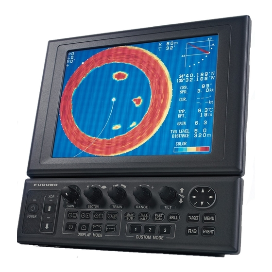
Features The CH-250 displays underwater objects on a bright 10.4” color LCD display, in 8 or 16 colors according to received echo strengths. Operating frequency is selectable among 60, 88 and 150 kHz. Eight operating modes provide information for virtually any fishing application. - Page 8 Usage Precautions The Motion Sensor MS-100 compensates for ship’s pitching and rolling. However, it does not compensate for load unbalance. If the equipment will not be used for a long time shut off the power to it at the mains switchboard to prevent battery discharge.
-
Page 9: System Configuration
SYSTEM CONFIGURATION INTERFACE UNIT IF-8000 Note 2 MONITOR UNIT MU-100C Navigator Control Unit Display Note 1 Unit VGA Ext. Monitor Remote Controller CH-256 TRANSCEIVER UNIT CONTROL UNIT CH-252 CH-253 MOTION SENSOR HULL UNIT 12-32 VDC SPEAKER DA T A/VIDEO OUT HULL UNIT 12-32 VDC Speaker... - Page 10 This page is intentionally left blank.
-
Page 11: Operational Overview
1. OPERATIONAL OVERVIEW Control Description Selects center bearing of training sector. Selects detection range. Switches training sector to 360˚ (horizontal mode), or 180˚ (vertical fan mode). Turns the power on/off. Selects scan speed/picture advancement speed. Raises the transducer Controls tilt angle. Adjusts receiver Selects center direction of sensitivity. -
Page 12: Remote Controller
Remote Controller The Remote Controller CH-256 (option) provides armchair control over range, tilt, target lock and range of sounding. Select tilt angle. Select display range. Selects range of sounding for full circle 360˚ (horizontal mode) or half circle 180˚ (vertical fan mode). Enables/disables target lock. -
Page 13: Turning The Power On/Off
Turning the Power On/Off 1.3.1 Power on This sonar has a demonstration mode which lets the operator become acquainted with the features of the sonar, without connecting the transducer. For further details see page 5-18. Press the [POWER] switch on the control unit till hear “click.” A beep sounds, the lamp above the switch lights and the last-used display appears. -
Page 14: Raising The Transducer
Raising, Lowering the Transducer 1.4.1 Lowering the transducer With the boat at the fishing ground, press the [ switch to lower the transducer. The lamp above the switch blinks while the transducer is being lowered and lights when it is completely lowered. The down arrow of the transducer status indicator at the top right corner of the display is filled when the transducer is completely lowered. -
Page 15: Adjusting Screen Brilliance, Panel Dimmer
Adjusting Screen Brilliance, Panel Dimmer Screen brilliance can be adjusted in nine steps and panel dimmer (backlighting) in four. 1. Press the [BRILL] key to open the dialog box for screen brilliance and panel dimmer. Do the next step within four seconds, otherwise the dialog box will be erased. BRILL:3 DIMMER:3 Figure 1-3 Brilliance, panel dimmer dialog box... -
Page 16: Selecting A Display
Selecting a Display This sonar has eight display modes and you may select one with one of the DISPLAY MODE keys. Refer to the chapter shown in the illustration for more information about each mode. Picture Picture DATA DATA HORIZONTAL EXPANDED HORIZONTAL This mode provides 360 degree coverage. -
Page 17: Adjusting The Gain
Adjusting the Gain The [GAIN] control adjusts the sensitivity of the receiver. Normally, the control is adjusted so that the bottom echo is displayed in reddish-brown mixed with red. Initially set the gain between “4” and “6” and then fine tune depending on fishing ground, etc. Too High Too Low Proper... - Page 18 2. The last-used menu is displayed. (In Figure 1-6 the COMN (COMMON) menu is selected.) To select a different menu, press to select MENU at the top of the screen and then press to select menu desired. 3. Press to select menu item desired. At the bottom of the screen menu help is provided.
-
Page 19: Horizontal Mode
2. HORIZONTAL MODE Operational Overview The figure below shows the typical horizontal mode operating sequence. Set center bearing of train Set tilt angle. sector. 6(a). Set scanning sector. Set range. Turn on the power. Adjust menu settings Adjust gain. (ex. TVG) as required. Lower the Measure range and Select appropriate... -
Page 20: Typical Horizontal Mode Display
Typical Horizontal Mode Display Tilt angle indicator (Indicates transducer tilt angle.) * Depth marker Horizontal max. range When depth data is input from external equipment, the depth Range and bearing markers marker shifts according to depth data. If the depth data is greater than the horizontal range, the Vertical max. -
Page 21: Selecting The Range
Selecting the Range The [RANGE] control selects the detection (display) range. Select the range according to either the fish species being searched or the depth desired. 15 ranges are available and minimum and maximum ranges depend on the transducer used. SEA SURFACE SEA SURFACE Range indicated... -
Page 22: Selecting Sector Width
Selecting Sector Width Sector means the width of the transducer training. Display sector (shown: 96˚) Figure 2-4 Display sector The [SECTOR] control selects the training (display) area among the sixteen positions shown in the table below. Clockwise rotation of the control increases the sector width; counterclockwise rotation decreases it. -
Page 23: Selecting Train Center
Selecting Train Center The [TRAIN] control selects the center direction of the detection range. The range of adjustment is 0 to 354 in increments of 6 . The selected bearing is shown with a filled circle, the train indicator, on the bearing scale. 0˚... -
Page 24: Bottom Echo And Tilt Angle
2.6.1 Bottom echo and tilt angle Refer to the illustration below. Case 1: Tilt angle 30 to 40 This tilt angle will display the entire bottom since it is captured by the full width of the beam. Case 2: Tilt angle 10 to 20 This tilt angle will only display half the bottom since it is only captured by the lower half of the beam. -
Page 25: Tilt Angle For Surface Fish
Points to consider Normally, a vertically distributed fish school is a better sonar target than the bottom, because it reflects the transmitted pulse back toward the transducer. In case 3, both fish schools “a” and “b” are presented. Generally speaking, however, midwater fish schools tend to be larger than bottom fish schools and they are often displayed near the bottom on the display. - Page 26 2.6.4 Suitable tilt angle The figure below illustrates the relationship among tilt angle, depth and detection range. Refer to it to find out the suitable tilt angle for a given depth/detection range. Tilt angle and beam coverage (frequency 60 kHz, vertical beamwidth 12 at -3 dB Range (m) (800)
-
Page 27: Selecting The Training Speed
Selecting the Training Speed The training speed selects how fast the transducer scans the sounding sector. Two choices are available, normal speed (default setting) and high speed, and one may be selected with the [FAST SCAN] key. Each time the key is pressed “NORM” (normal speed) or “FAST” (high speed) momentarily appears at the screen top. -
Page 28: Event Marker
Event Marker The event marker functions to mark important locations on the screen, and five event markers may be inscribed. Each time the [EVENT] key is pressed the “latest event marker” ( ) is inscribed at the cursor location and all previously entered event markers are shown by the “previous event marker”... -
Page 29: Range And Bearing Markers
2.9.2 Deleting all event markers All event markers can be erased from the screen as follows: 1. Operate the Omnipad to place the cursor outside the display area. 2. Press the [EVENT] key to show the following dialog box. Do the next step within four seconds, otherwise the dialog box will be erased. -
Page 30: Adjusting The Picture
2.11 Adjusting the Picture 2.11.1 Suppressing bottom and surface reflections In shallow fishing grounds, excessive sea surface and bottom reflections often interfere with wanted fish echoes and they cannot be eliminated sufficiently with the TVG controls. In such cases, try to reduce the output power, without turning down the gain. The picture becomes clearer when output power is reduced rather than when the gain is decreased. -
Page 31: Suppressing Bottom Tail
2.11.2 Suppressing bottom tail As described earlier, fish schools near the bottom are sometimes difficult to detect because you have to discriminate fish echoes from the bottom reflections. To discriminate fish echoes near the bottom, select the short Tx pulselength on the COMN menu to decrease the tail of bottom reflections. - Page 32 To adjust TVG: 1. Press the [MENU] key to open the menu. 2. Press to select MENU and then press to select HORZ. COMN HORZ VERT ES PRESET SYS MENU TVG LEVEL TVG DISTANCE GAIN ADJUST RES. COLOR TARGET KEY REVERSE LOCK MODE AUTO...
-
Page 33: Erasing Weak Echoes
6. Press to close the TVG distance dialog box and return to the HORZ menu. 7. To suppress reflections by the sea surface or plankton, select TVG LEVEL and press 8. Press to adjust TVG LEVEL, considering sea conditions. A setting between 2.0 and 5.0 should provide satisfactory results. - Page 34 2.11.5 Enlarging fish echoes (expanded horizontal display) Fish echoes may be enlarged 1.5 times by using the expanded horizontal display. Press the key to show the expanded horizontal display. The direction of expansion depends on the train direction as below. Train center direction Position after expansion Remarks...
-
Page 35: Target Lock
2.12 Target Lock Three types of target lock modes are available: Manual reverse: The transducer train direction is reversed manually. This is the default setting, and is available in the horizontal and vertical fan modes. Position: Tracks stationary position (such as a reef) using position data from a navigator. -
Page 36: Position Mode
2.12.3 Position mode This mode tracks a stationary position (such as a reef) using position data fed from a navigator. Note1: This function is inoperative in the echo sounder mode. In the vertical fan mode the reverse mode is automatically selected regardless of the setting in paragraph 2.12.1. Note2: This mode requires position data. -
Page 37: Echo Mode
2.12.4 Echo mode The echo mode tracks a fish school either automatically or manually. The default setting is automatic, and you can select automatic or manual with “LOCK MODE” in the HORZ menu. Automatic echo tracking mode The automatic echo target lock function automatically tracks a fish school appearing in the operator-selected target lock zone. - Page 38 When the fish echo is lost the tilt angle is automatically changed as below to continue tracking the echo: Tilt changed to search [(A + 10˚) (A - 10˚) Detection area displayed once again and target lock indicator lights. A Tilt angle at start of target lock 5.
-
Page 39: Horizontal Menu Overview
2.13 Horizontal Menu Overview This section presents an overview of the items on the HORZ menu. 1. Press the [MENU] key to open the menu. 2. Press to select MENU and then press to select the HORZ menu. COMN HORZ VERT ES PRESET SYS MENU TVG LEVEL... - Page 40 RES. COLOR: Sets transfer characteristics of input signal level versus display echo level. Echo strength is emphasized in order of CUBE, SQUARE, LINEAR, LOG, and you can observe the characteristics of each by watching the color bar as you change the setting. LOG: Displays weak to strong echoes in their respective levels.
-
Page 41: Interpreting The Horizontal Display
2.14 Interpreting the Horizontal Display This section provides information necessary for interpreting the horizontal display. 2.14.1 How the horizontal mode picture is painted The wide sounding beam is emitted from the soundome at a certain tilt angle (see hatched area in the figure below). -
Page 42: Sample Echo Displays
2.14.2 Sample echo displays Bottom echoes When the tilt angle is changed, the bottom echo illustrated below will appear on the display. When the tilt is decreased (toward 0 , the bottom trace becomes wider and weaker. By observing the bottom condition on the display, the skipper can prevent net damage. (A) Flat bottom Tilt angle: 10˚... -
Page 43: Fish Schools
Fish schools A fish school appears as a mass of echoes on the screen. The color of the mass shows the density of fish schools on the sonar beam. To find distribution and center point of a fish school, try several different tilt angles. (A) Sea surface fish Tilt angle: 0˚... - Page 44 Sea surface reflections To reduce sea surface reflections, set the tilt angle to 5 or higher, so the upper edge of the sonar beam does not hit the sea surface, or adjust TVG. When a decreased tilt angle is used, sea surface reflections cover a large area as illustrated below.
- Page 45 Sidelobe echo (false echo) An ultrasonic wave is emitted only in the direction set by the [TILT] control, however there are some emissions outside the main beam. These are called sidelobes. The energy of the sidelobe is fairly weak but when the water is comparatively shallow and the bottom is rocky and hard, strong signals are detected by the sidelobe.
-
Page 46: Combination Display Examples
2.14.3 Combination display examples Horizontal/history display Press the key to display the horizontal/history display. Tilt angle Cursor position Tilt angle indicator Range data R 40 m Interference rej. ON T 40˚ B148˚ Target lock indicator Transducer status indicator Own ship marker 34 12. - Page 47 Horizontal/video plotter display Press the key to display the horizontal/video plotter display. Tilt angle Cursor position Tilt angle indicator Range data R 40 m Interference rej. ON T 40˚ B154˚ Target lock indicator Transducer status indicator Own ship marker 34 12. 343' N Position in latitude*, 134 34.
- Page 48 Horizontal/strata display Press the key to display the horizontal/strata display. Tilt angle Cursor position Tilt angle indicator Range data R 40 m Interference rej. ON T 40˚ B133˚ Target lock indicator Transducer status indicator Own ship marker 34 12. 343' N Position in latitude*, 134 34.
- Page 49 Color bar for the strata display The depth of the bottom echo in all directions is displayed in the sub window, in the colors set by the color bar for the strata display. Strongest Weakest ˚ ˚ ˚ ˚ ˚ ˚...
- Page 50 Projection in fore direction and strata display Color "b" on the color bar is displayed here. STBD +90˚ -90˚ PORT Color "a" on the color bar Color "b" Color "a" Figure 2-31 Projection in fore direction and strata display Depth becoming shallower gradually in fore direction and strata display Color "b"...
-
Page 51: Vertical Fan Mode
3. VERTICAL FAN MODE Operational Overview The figure below shows the typical vertical fan mode operating sequence. Set center bearing of train Set tilt angle. sector. 7(a). Set scanning sector. Set range. Adjust menu settings Turn on the power. Adjust gain. (ex. -
Page 52: Typical Vertical Fan Mode Display
Typical Vertical Fan Mode Display Bearing indicator (Shows training direction.) FORE ship PORT STARBOARD Vertical range Horizontal range Training indicator Interference Transducer status indicator rejector ON Filled arrow: Respective action completed Blinking arrow: Action in progress Heading* Cursor position Horizontal range scale data 60 m 100 m... -
Page 53: Selecting The Range
Selecting the Range The [RANGE] control selects the detection (display) range, in 15 settings. Select the range according to either the fish species being searched or the depth desired. Each time the control is operated the newly selected range briefly appears in large characters at the screen top. Range is permanently displayed at the top right-hand corner of the screen. -
Page 54: Selecting Train Center
Selecting Train Center The [TRAIN] control determines the bearing of the vertical fan beam, from 0 to 180 . Bearing of beam position can be found with the train indicator. 0˚ (360˚) 6˚ 12˚ 18˚ 180˚ Train Indicator Train of Vertical Fan Beam Train indicator TRAIN Figure 3-4 Train indicator... -
Page 55: Selecting Display Sector
Selecting Display Sector Sector means the width of the transducer training, from 6 to 180 Sector (Shown: 24˚) 24˚ Figure 3-6 Sector The [SECTOR] control selects the training area among the sixteen positions shown in the table below. Clockwise rotation of the control increases the sector width; counterclockwise rotation decreases it. -
Page 56: Selecting Sector Center
Selecting Sector Center The center direction of the sounding beam in the vertical direction can be changed with the [TILT] control. The setting range is 0 to 180 in increments of 6 . Select the setting which places the sector center in the middle of the detection range. Sector center angle set with TILT control In the example display at left, the sector... -
Page 57: Selecting The Training Speed
Selecting the Training Speed The training speed selects how fast the transducer scans the display sector. Two choices are available, 3 (normal speed, default setting) and 6 (high speed), and one may be selected with the [FAST SCAN] key. Each time the key is pressed the display momentarily shows “NORM” (normal speed) or “FAST”... -
Page 58: Event Marker
Event Marker The event marker functions to mark important locations on the screen, and five event markers may be inscribed. Each time the [EVENT] key is pressed the “latest event marker” ( ) is inscribed at the cursor location and all previously entered event markers are shown by the “previous event marker”... -
Page 59: Depth And Horizontal Range Markers
1 Deleting all event markers All event markers can be erased from the screen as follows: 1. Operate the Omnipad to place the cursor outside the display area. 2. Press the [EVENT] key to show the following dialog box. Do the next step within four seconds, otherwise the dialog box will be erased. -
Page 60: Adjusting The Picture
3.11 Adjusting the Picture 3.11.1 Displaying weak echoes clearly Echoes from targets (such as the bottom or a fish) return to the transducer in order of the distance to them, and when their intensities are compared at the transducer face, those from nearer targets are generally stronger when their reflecting properties are nearly equal. -
Page 61: Suppressing Noise And Interference
4. Press to adjust TVG distance, considering sea conditions. The larger the figure the greater the distance at which the TVG works. Distance ..10.0 Setting Meters ..1000 Feet 1040 3280 Passi/braza ..Hiro 5. -
Page 62: Vertical Menu Overview
3.12 Vertical Menu Overview This section presents an overview of the items on the VERT menu. 1. Press the [MENU] key to open the menu. 2. Press to select MENU and then press to select the VERT menu. COMN HORZ VERT ES SHORT-CUT SYS MENU... -
Page 63: Interpreting The Vertical Fan Display
3.13 Interpreting the Vertical Fan Display This section provides information necessary for interpreting the vertical fan display. 3.13.1 How the vertical fan mode picture is painted The sounding beam is emitted and the information (target echoes) obtained by the beam appears in the corresponding sector as it appears on the sonar mode. - Page 64 3.13.2 Sample echo displays Port-starboard picture (bottom) You can see fish echoes at the center-right of the screen. The bottom is displayed wider as the distance from the ship’s position increases. Therefore, it may be difficult to discriminate bottom fish. Own ship STBD PORT...
- Page 65 Display of net hauling This is an example of net hauling display. The location of the net is indicated clearly. FORE Figure 3-20 Net hauling and sonar picture False echo In shallow water (depth less than 100 m) detection, unwanted echoes shown in the figure may appear.
- Page 66 3.13.3 Horizontal/vertical fan display Press the key to display the horizontal/vertical fan display. Tilt angle Vertical fan Cursor data Tilt angle indicator bearing cursor Range 40 m 40˚ B156˚ Interference rejector Target lock indicator Transducer status indicator Own ship marker 34 12.
- Page 67 SECTOR control For the vertical fan display: When the display sector is 6° (minimum) the tilt angle of the horizontal and vertical fan modes are interlocked and each transmission on the horizontal display is reflected on the vertical fan display. The message TILT ANGLE MONITOR WINDOW momentarily appears on the screen and the vertical bearing cursor disappears.
- Page 68 This page is intentionally left blank.
-
Page 69: Echo Sounder Mode
4. ECHO SOUNDER MODE Operational Overview The figure below shows the typical echo sounder mode operating sequence. Set tilt angle. Select display sector. Set range Adjust menu settings (turn on A-scope Turn on the power. display, etc.). Adjust gain. Lower the transducer. Measure range to fish Select echo sounder school with cursor. -
Page 70: Typical Echo Sounder Display
Typical Echo Sounder Display Press the key to display the echo sounder picture. Tilt angle indicator Bearing (Shows tilt angle of transducer.) indicator (Shows train Interference Tilt angle direction.) rejector ON Range Heading Transducer status indication Cursor position R 10 m T 60 Minute marker 34 12. -
Page 71: Selecting The Range
Selecting the Range The [RANGE] control selects the detection (display) range, in 15 settings. Select the range according to either the fish species being searched or the depth desired. Each time the control is operated the newly selected range briefly appears in large characters at the screen top. Range is permanently displayed at the top right-hand corner. -
Page 72: Train Direction
Train Direction The sounding beam may be directed toward fore, aft, port or starboard. Operate the [TRAIN] control to select sounding beam direction. Each setting on the control is an increment of 6 . The train indicator at the top of the screen shows training direction: 0 , fore direction; 90 , starboard direction;... -
Page 73: Measuring Range By Cursor
Measuring Range by Cursor Use the cursor to display the range from own ship to the cursor location. Use the Omnipad to place the cursor where desired. The range to the cursor appears at the upper left-hand corner of the screen. Range to cursor : Range DATA... -
Page 74: Deleting All Event Markers
4.8.1 Inscribing the event marker 1. Operate the Omnipad to place the cursor on the location desired for an event marker. 2. Press the [EVENT] key to inscribe the event marker. Display area "Previous event marker" DATA A-SCOPE DISPLAY "Latest event marker" To delete all event markers, place the cursor outside the display area and... -
Page 75: Range Marker
Range Marker The range marker functions to measure the range to a target echo (fish school, bottom, etc.) 1. Operate the Omnipad to place the cursor on the location desired. 2. Press the [R/B] key to display the range marker. The range marker appears along with range indication. - Page 76 COMN HORZ VERT SHORT-CUT SYS MENU TVG LEVEL TVG DISTANCE GAIN ADJUST RES. COLOR A-SCOPE : SELECT : CHANGE MENU: END Figure 4-7 ES menu 3. Press to select TVG DISTANCE and press . The following dialog box appears. TVG DISTANCE GAIN 200m 4.
- Page 77 4.10.2 Finding echo strength (A-scope display) The A-scope display shows echoes at each transmission with amplitudes and tone proportional to their intensities on the right 1/4 of the screen. It is useful for estimating the kind of fish school and bottom composition. 1.
-
Page 78: Echo Sounder Menu Overview
4.11 Echo Sounder Menu Overview This section presents an overview of the items on the ES menu. 1. Press the [MENU] key to open the menu. 2. Press to select MENU and then press to select the ES menu. COMN HORZ VERT SHORT-CUT SYS MENU TVG LEVEL... - Page 79 RES. COLOR: Sets transfer characteristics of input signal level versus display echo level. Echo strength is emphasized in order of CUBE, SQUARE, LINEAR, LOG. You can see the characteristics of each by watching the color bar as you change the setting. The default setting is LOG.
- Page 80 This page is intentionally left blank.
-
Page 81: Menu Operation
5. MENU OPERATION This chapter provides menu operating information on menus not previously discussed: COMN (Common) menu, PRESET (or SHORT-CUT, depending on the setting of CUSTOM KEY on the SYSTEM SETTING 1 menu) and SYS (System) menu. COMN Menu 1. Press the [MENU] key to open the menu. 2. - Page 82 5.1.1 COMN menu description WHITE MARKER: Displays desired echo in white. It is useful for discriminating bottom fish from the seabed. The setting range for the 8-color display is OFF, 1-7, and for the 16-color display, OFF, 1-15. The default setting is “0.” SIG LEVEL: Dirty water or reflections from plankton may be painted on the screen in green or light-blue.
-
Page 83: Short-Cut Menu, Preset Menu
Short-cut Menu, Preset Menu These menus program the CUSTOM MODE keys [1], [2] and [3], and one of the menus appears according to the setting of CUSTOM KEY on the SYSTEM SETTING 1 menu. Short-cut key: One-touch activation of corresponding dialog box. This is the default setting. Preset key: One-touch setup of mode, sector, train, range, tilt and speed controls. - Page 84 ** SYSTEM MENU ** SYSTEM SETTING: RANGE-SONAR MODE RANGE-VERTICAL MODE RANGE-E/S MODE COLOR PALETTE LANGUAGE SYSTEM BACKUP LOAD BACKUP DATA HEADING OFFSET ADJ MOTION SENSOR TX FREQ ADJUST TEST TEST PATTERN DEMO MODE DEFAULT : SELECT : MENU DISPLAY MENU: END Figure 5-3 System menu 5.
-
Page 85: Preset Key
5.2.2 Preset key 1. Select PRESET KEY following the procedure in paragraph 5.2.1 on page 5-3. 2. Press the [MENU] key to open the menu. 3. Press to select MENU, and then press to select PRESET. MENU COMN HORZ VERT ES PRESET MODE SECTOR... - Page 86 5.2.3 Short-cut key The default settings are key [1], interference rejector; key [2], signal level, and key [3], background color. The operator may change their functions as desired. Note: In the combination modes the short-cut key operation is only possible from the main window.
-
Page 87: Sys Menu
SYS Menu This menu provides items which may be set according to operator’s preference. A demonstration mode is provided to acquaint you with the many functions of this equipment, and it may be used without connection of the transducer. 1. Press the [MENU] key to open the menu. 2. - Page 88 SYSTEM SETTING 1 menu 1. Display the SYSTEM menu and press to select SYSTEM SETTING. 2. Press 3. Press to MENU. 4. Press to select “1.” ** SYSTEM SETTING 1 ** MENU SHIP'S POSITION CURRENT DATA FLOW FROM FLOW TO HEADING INDICATION : TRUE NORTH MARK : OFF...
- Page 89 HEADING INDICATION: Selects heading indication format, true (default setting) or azimuth, for the echo sounder and vertical fan modes. The default setting is TRUE. Requires heading data. NORTH MARK: Turns the north marker on or off (default setting). Requires heading data. CSE DATA: Selects heading data source, navigator or gyrocompass, to draw ship’s track.
- Page 90 SYSTEM SETTING 2 menu description ** SYSTEM SETTING 2 ** MENU AUTO RETRACTION (OFF, 5-15 kt) SPEED ALARM/MESSAGE : SOUNDOME SER.NO : ~999 1000~ DEFAULT SETTING : NO MAXIMUM ALLOWABLE SPEED IS 15 KNOTS WHILE THE SOUNDDOME IS BEING RETRACTED. IF VESSEL HAS RAPID ACCELERATION CAPABILITIES, AUTO RETRACTION SETTINGS OF 10-12 KNOTS ARE MANDATORY TO AVOID CATASTROPHIC DAMAGE TO SOUNDOME ASSY.
- Page 91 SPEED ALARM MESSAGE: Turn on (default setting) to display speed alarm message and sound the audio alarm when ship’s speed exceeds allowable speed for a given transducer operation. The audio alarm can be silenced with the [R/B] key. [ ] pressed to lower transducer Message 1 appears.
- Page 92 DEFAULT SETTING: Select YES and press the [MENU] key to restore all default system menu settings. Several beeps sound while default settings are being restored and then normal operation is restored. ** FACTORY SETTING ** ARE YOU SURE? NOTE: ALL THE SYSTEM SETTING WILL BE CHANGED TO FACTORY SETTING.
- Page 93 5.3.2 Sonar (horizontal) mode range settings The user may preset horizontal mode ranges as desired. 1. Select RANGE-SONAR MODE at the SYS menu and then press ** RANGE-SONAR MODE ** 10 (10-1600m) 1000 TRACK DISP 500 (500-5000m) DEFAULT SETTING : : CHANGE MENU: END : SELECT...
- Page 94 5.3.3 Vertical fan mode range settings As with the horizontal mode, the user may preset the vertical fan mode’s ranges. 1. Select RANGE-VER MODE at the SYS menu and then press ** RANGE-VER MODE ** 10 (10-600m) DEFAULT SETTING : : CHANGE MENU: END : SELECT...
-
Page 95: Echo Sounder Mode Range Settings
5.3.4 Echo sounder mode range settings As with the horizontal and vertical fan modes, the user may preset the echo sounder mode’s ranges. 1. Select RANGE-E/S MODE at the SYS menu and then press ** RANGE-E/S MODE ** 10 (10-600m) DEFAULT SETTING : : CHANGE MENU: END... -
Page 96: Color Palette
5.3.5 Color palette The color palette lets the user change the color of echoes, background, text and menu as desired. Cursor ** COLOR PALETTE ** 3 4 5 6 7 8 9 10 11 12 13 14 15 ECHO Arrow BKGD TEXT MENU... -
Page 97: System Backup
5.3.6 Language Menu language can selected to English or Japanese and the default language is English. ** LANGUAGE ** LANGUAGE: JAPANESE ENGLISH : CHANGE MENU: END Figure 5-17 Language menu 5.3.7 System backup User settings can be backed up with the menu item SYSTEM BACKUP. ** SYSTEM BACKUP ** ARE YOU SURE? NOTE: OVERWRITE PREVIOUS BACKUP DATA. -
Page 98: Transducer Frequency Adjustment
5.3.9 Transducer frequency adjustment If the CH-250 is receiving interference from a video sounder or other sonar on board your ship, adjust the frequency of the CH-250’s transducer to reduce the interference. ** TX FREQ ADJUST ** FREQ SHIFT 60.0 kHz (57-63 kHz) -
Page 99: Restoring All Default Settings
5.3.11 Restoring all default settings The item DEFAULT lets you restore all default menu settings. Select YES and press the [MENU] key to restore all default settings. Note that settings stored in SYSTEM BACKUP are not disturbed. ** DEFAULT ** ARE YOU SURE? NOTE: RESET ALL THE SETTINGS INCLUDED IN THE SYSTEM MENU TO DEFAULT. - Page 100 This page is intentionally left blank.
-
Page 101: Maintenance, Troubleshooting
6. MAINTENANCE, TROUBLESHOOTING This chapter provides information necessary for keeping the equipment in good working order. WARNING Do not open the equipment. Hazardous voltage which can cause electrical shock exists inside the equipment. Only qualified personnel should work inside the equipment. Preventive Maintenance Check the following points monthly. -
Page 102: Hull Unit Maintenance
Hull Unit Maintenance 6.3.1 Lubrication Grease the raise/lower screw shaft once a year. Also, grease the raise/lower main shaft (upper part of the grease cotton retainer) twice a year. These parts can be accessed by removing the raise/lower drive assembly cover. 6.3.2 Manually raising, lowering transducer WARNING... -
Page 103: Transducer Maintenance
Transducer Maintenance When the ship is dry-docked remove marine growth from the transducer with fine sandpaper or a piece of wood. CAUTION Do not paint the transducer face. Loss of sensitivity will result. Do not use plastic solvents to clean the transducer. -
Page 104: Troubleshooting
Debris may be on sea surface. Reject unwanted noise with the interference rejector on the COMN menu. Picture does not Problem in tilt mechanism or control line. Contact a FURUNO agent or change when tilt angle dealer for advice. is changed. (Bottom is... -
Page 105: Error Messages
6.7 Error Messages The table below shows the error messages which may appear on the display. All error messages are accompanied by an audio alarm, which you may silence with the [R/B] key. Message Meaning, Remedy Hull Unit HULL UNIT Hull unit is not powered. -
Page 106: Diagnostics
The program numbers of the MAIN and PANEL programs appear at the top of the display. The ROM, RAM, VRM, NMEA and PANEL CPU are checked for proper operation and the results displayed as OK or NG (No Good). For NG contact a FURUNO agent or dealer for advice. - Page 107 TRAIN shows a figure between 355-359 if normal. NG appears in case of train error. TEST COUNT shows the number of times the test has been consecutively executed. At the bottom of the screen there are two major groups of zeroes (0), and they represent the keys and controls on the control panel and remote controller.
-
Page 108: Test Pattern
Test Pattern A test pattern can be displayed to check for proper display of colors. 1. Press the [MENU] key to open the menu. 2. Press to select MENU, and then press to select SYS. 3. Press to select GO TO SYS MENU. 4. -
Page 109: Menu Tree
MENU TREE [MENU] key COMMON menu WHITE MARKER ( OFF , 1-15) SIG LEVEL ( OFF , 1-14) COLOR ( 16 , 8) DEFAULT SETTINGS SHOWN BKGD COLOR (1, 2 , 3) IN BOLD ITALIC. TX POWER ( MAXIMUM , MINIMUM) PULSELENGTH ( LONG , SHORT) TX RATE (EXTERNAL, 1-10;... - Page 110 [MENU] key SYSTEM menu SYSTEM SETTING (See next page.) RANGE-SONAR MODE (all default ranges) 60 kHz (min. range: m, 10; ft, 40 ft; fa, p/b, hiro, 5, max. range: m, 1600; ft, 5000; fa, 800: p/b, hiro, 1000) 88 kHz (min. range: m, 10; ft, 40 ft; fa, p/b, hiro, 5, max. range: m, 1600; ft, 4000; fa, 700;...
- Page 111 SYSTEM SETTING 1 SHIP'S POSITION ( L/L , LOP) CURRENT DATA ( OFF , FLOW FROM, FLOW TO) HEADING INDICATION ( TRUE , AZ) NORTH MARK ( OFF , ON) CSE DATA ( NAV , GYRO) NAV DATA ( GPS , LoranC, LoranA, DR, DECCA, OTHERS) TVG CORRECTION ( OFF, 1/2, 1/1) UNIT ( m , ft, fa, HIRO, P/B) TEMP (˚...
-
Page 112: Specifications
SPECIFICATIONS OF 10.4 INCH COLOR SEARCHLIGHT SONAR CH-250 GENERAL Display System 10.4 inch Color LCD Transmit Frequency 60, 88 or 150 kHz selected Output Power 0.8 kW (60 kHz) to 1.2 kW (150 kHz) Range (factory setting) Detection Range (m) - Page 113 Audio Monitor 2 W output (4 ohms), Freq. 1.0 kHz (external speaker required) 2.10 Event Mark 5 points 2.11 Hue Low level enhanced echo disappeared 2.12 Red Color Enhancement Strong echo indicated as expanded to range direction 2.13 Arrival Mark Vector estimated point after 10 seconds to 6 min.
- Page 114 Scanning Angle 6 to 180 , 12 step Scanning Center 0 to 180 , 6 step Scanning Step Angle Normal: 3 , High speed: 6 Time to Train 360 , 6 step Transceiver Beam Width Frequency Vertical Horizontal (-3 dB) 60 kHz: 88 kHz: 11.5...
-
Page 115: Index
INDEX Event marker AGC .............. 2-22 deleting from echo sounder mode....4-6 A-scope display ..........4-9 deleting from horizontal mode....2-11 Audio level ............ 2-22 deleting from vertical fan mode ....3-9 Automatic tilt ..........2-22 inscribing from echo sounder mode ... 4-6 inscribing from horizontal mode .... - Page 116 System configuration........vii SYSTEM SETTING 1 menu......5-8 Position display format ........5-8 SYSTEM SETTING 2 menu......5-10 POWER switch ..........1-3 PRESET menu ..........5-5 Pulselength........... 2-13 TARGET key ........2-17 - 2-19 Target lock echo mode..........2-19 R/B key manual reverse mode ......