Table of Contents
Advertisement
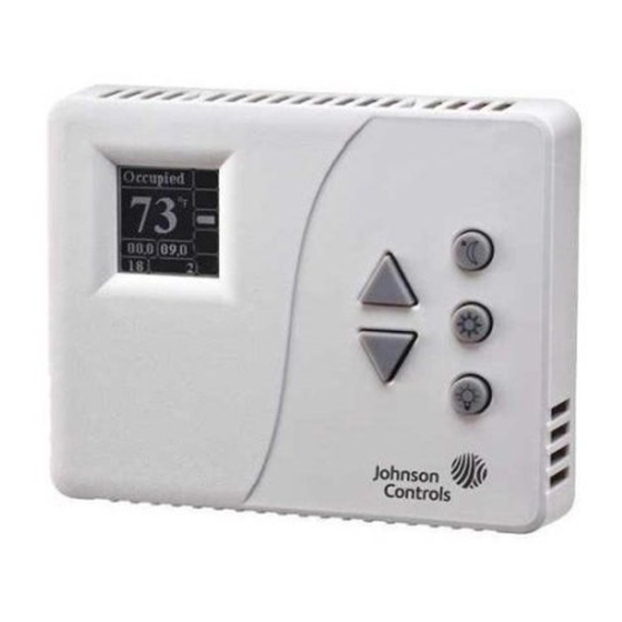
WT-4000 Series Pneumatic-to-Direct Digital Control (DDC)
Room Thermostats
Installation Instructions
WT-4002-MCR, WT-4002-MCM,
WT-4002-MFR, WT-4002-MFM
Application
The WT-4000 Series Pneumatic-to-Direct Digital
Control (DDC) Room Thermostats provide reliable
zone comfort and enhanced energy economy via
remote monitoring and temperature setpoint
management. This arrangement provides greater
energy policy compliance, and facilitates trending of
floor space usage in commercial, industrial, and
municipal HVAC environments.
The WT-4000 Series Room Thermostats are ideally
suited for energy-saving, pneumatic-to-DDC building
upgrades. Designed for non-invasive replacement
of existing manual pneumatic thermostats, the
WT-4000 Series Room Thermostats provide a number
of DDC features, including remote wireless setpoint
control and occupancy scheduling, and continuous
room temperature, branch line pressure, and battery
status monitoring. All of these features were previously
unavailable in existing pneumatic HVAC control
systems.
The innovative design of the WT-4000 Series Room
Thermostats completely reshapes the pneumatic
HVAC control industry. The room thermostat itself does
not utilize any mechanical parts. A solid state
temperature sensor replaces the bi-metallic strip
elements for precise room temperature monitoring. In
addition, an advanced piezoelectric air valve replaces
the mechanical relay for improved branch line pressure
control. All of these technologies provide longer, more
dependable, and maintenance-free operation.
Models are available for wireless mesh
communications, or they can be configured in the field
for stand-alone applications. In a wireless mesh
network application, the WT-4000 Series Room
Thermostat communicates with the controller by
means of a Johnson Controls® WT-ROUTER Router
and Johnson Controls WT-BAC-IP Gateway.
Some WT-4000 Series Room Thermostats include a
binary dry contact input for an occupancy sensor (field
furnished), to detect motion and determine if a space is
occupied. This feature maximizes up to 30% energy
savings in high-energy usage environments such as
schools, dormitories, offices, and hospitals by adjusting
the temperature of the space based on the occupancy
status.
Refer to the
WT-4000 Series Pneumatic-to-Direct Digital Control (DDC)
Room Thermostats Installation Instructions
24- 10732- 5, Rev . D
QuickLIT website
for the most up-to-date version of this document.
All WT-4000 Series Room Thermostats include an
LCD, with either a Fahrenheit or Celsius temperature
display. Depending on the model chosen, the room
thermostat can transmit sensed temperature, setpoint
temperature, occupancy status, and low battery
conditions to an associated router and gateway. The
WT-4000 Series Room Thermostat is designed for
indoor, intra-building applications only.
The WT-4000 Series uses a proprietary
direct-sequence, spread-spectrum RF technology,
and operates on the 2.4 GHz Industrial, Scientific, and
Medical (ISM) band. The room thermostat meets the
IEEE 802.15.4 standard for low power, low duty cycle
RF transmitting systems.
IMPORTANT: The WT-4000 Series
Pneumatic-to-DDC Room Thermostat is intended to
provide an input to equipment under normal
operating conditions. Where failure or malfunction of
the room thermostat could lead to personal injury or
property damage to the controlled equipment or
other property, additional precautions must be
designed into the control system. Incorporate and
maintain other devices, such as supervisory or
alarm systems or safety or limit controls, intended to
warn of or protect against failure or malfunction of
the room thermostat.
IMPORTANT: Le WT-4000 Series
Pneumatic-to-DDC Room Thermostat est destiné à
transmettre des données entrantes à un équipement
dans des conditions normales de fonctionnement.
Lorsqu'une défaillance ou un dysfonctionnement du
room thermostat risque de provoquer des blessures
ou d'endommager l'équipement contrôlé ou un autre
équipement, la conception du système de contrôle
doit intégrer des dispositifs de protection
supplémentaires. Veiller dans ce cas à intégrer de
façon permanente d'autres dispositifs, tels que des
systèmes de supervision ou d'alarme, ou des
dispositifs de sécurité ou de limitation, ayant une
fonction d'avertissement ou de protection en cas de
défaillance ou de dysfonctionnement du room
thermostat.
1
Part No. 24-10732-5, Rev. D
Issued August 2017
Advertisement
Table of Contents

Related Manuals for Johnson Controls WT-4002-MCR


Summary of Contents for Johnson Controls WT-4002-MCR
-
Page 1: Installation Instructions
Thermostat communicates with the controller by supplémentaires. Veiller dans ce cas à intégrer de means of a Johnson Controls® WT-ROUTER Router façon permanente d'autres dispositifs, tels que des and Johnson Controls WT-BAC-IP Gateway. systèmes de supervision ou d'alarme, ou des Some WT-4000 Series Room Thermostats include a dispositifs de sécurité... -
Page 2: North American Emissions Compliance
WT-4000 Series Pneumatic-to-DDC Room North American Emissions Compliance Thermostats, as well as the Johnson Controls WT-BAC-IP Gateway. United States Next, measure the radial distances between each Compliance Statement (Part 15.19) -
Page 3: Tools And Hardware Required
Dimensions 4-23/32 13/16 (120) (21) 3-3/4 (95) Figure 1: WT-4000 Series Pneumatic-to-DDC Room Thermostat, Dimensions, in. (mm) Mounting To document the location of where each wireless device is installed The WT-4000 Series Room Thermostats require the WT-BAC-IP Gateway and WT-ROUTER Router to Mounting Procedure operate as a complete wireless solution. - Page 4 d. Mounting holes on the wallplate are designed Figure 2 illustrates the LCD during room to fit a standard electrical box. If additional thermostat initialization. mounting holes are required, mark the locations on the mounting surface. e. Remove the wallplate from the mounting surface and drill any additional mounting holes as needed at each of the marked locations.
-
Page 5: Safety Measures For Electrostatic Sensitive Devices (Esds)
The room thermostat operates in the Occupied existing pneumatic system is contaminated with water Mode with the following default settings: or oil, Johnson Controls recommends installation of a • Setpoint temperature: 70°F (21°C) pre-filter before each room thermostat to protect the device from contaminants and failure. -
Page 6: Setup And Adjustments
Setup and Adjustments Since the room thermostats are battery-powered devices with internal memory, they can be configured prior to, or right after, installation. Johnson Controls recommends that all of the room thermostats be configured before installation, to prevent any possible issues with operation. -
Page 7: Lcd Details
2: Two or more connections exist and the room 1024 Time and Date need to be configured (Stand-Alone Mode) thermostat is operating properly. Product error; contact the local Other Johnson Controls representative Number WT-4000 Series Pneumatic-to-Direct Digital Control (DDC) Room Thermostats Installation Instructions... -
Page 8: Adjusting The Room Setpoint Temperature
Received Signal Strength Indicator c. When the setpoint is displayed, keep pressing the Up/Down buttons to reach the desired Indicates the relative strength of the wireless signal room setpoint temperature. between the room thermostat and the device it is communicating with. d. -
Page 9: Using The Shoulder Mode Button
Using the Shoulder Mode Button Configuration The Shoulder Mode button allows the WT-4000 Series The following steps describe pre-installation, Room Thermostat to be placed into a shallow setback device-level configuration. mode. When the room thermostat is activated, it does Room Thermostat Configuration Mode not use HVAC equipment as long as the temperature is 1. - Page 10 Net Config Screen Maintenance – Pneumatic Settings 1. While in the Configuration Mode, press the 1. While in the Configuration Mode, press the Up/Down buttons to select the Net Config option Up/Down buttons to select the Maintenance option (Figure 6). (Figure 8).
- Page 11 11. Change the proportional band – proportional 6. Press to confirm the selection. range/throttling range as desired (Figure 13). 7. Change the setpoint pressure as desired Dir Acting (Figure 11). SP Psi Gain Dir Acting Prop Bnd ...
- Page 12 Commissioning 14. Press to confirm the selection. Table 2 includes a list of configurable settings that define how WT-4000 Series Room Thermostat pneumatic pressure commands correlate with the 15. Press to go back to the previous screen temperature values. Refer to the HVAC equipment button when done.
-
Page 13: Operation
Operation The WT-4000 Series Room Thermostats are designed to support any 0 to 22 psig (0 to 152 kPa) pneumatic The WT-4000 Series Pneumatic-to-DDC Room HVAC control system. Variation in branch line pressure Thermostats are regulated by a number of operational is proportional to the deviation of room temperature modes that can be triggered by inputs such as changes from the setpoint. - Page 14 In a DA room thermostat configuration, the branch line In a wireless mesh network, the room thermostat pressure increases in response to an increase in room operates as a battery-powered end node. Being an end temperature. When the room temperature is within the node, the room thermostat does not operate as a router ±1F°...
-
Page 15: Stand-Alone Operation
Stand-Alone Operation A complete 7-day schedule consists of two independent components: Stand-Alone Room Thermostat Occupancy • Weekday Schedule – Monday through Friday Programming The WT-4000 Series Room Thermostats can operate • Weekend Schedule – Saturday through Sunday as stand-alone pneumatic-to-DDC room thermostats Each component is split into two parts to be scheduled with an independent time clock, and can be as Occupied or Unoccupied Mode:... - Page 16 The start time of each schedule part is automatically the end time of the previous schedule part. For example, when the occupied schedule is 6 A.M. to 6 P.M., the Occupied Mode starts at 6 A.M. and the Unoccupied Mode starts at 6 P.M. Figure 18 and Figure 19 illustrate the Occupied and Unoccupied Mode schedule setup.
- Page 17 Configuring the Room Thermostat for Stand-Alone Stand-Alone Room Thermostat Configuration Operation To set the time and program the stand-alone room The WT-4000 Series Room Thermostats can be thermostat occupancy schedule and temperature configured in the field for stand-alone applications. setpoints: 1.
- Page 18 2. Use the Up/Down buttons to select Standalone on 7. Press to confirm the selection. the menu (Figure 22). 8. Repeat Step 5 through Step 7 until all of the menu Standalone options are configured correctly. Press the Up Net Config button or the Down button to scroll...
- Page 19 12. Set the Weekday 2 schedule (Figure 26). Press to open a specific menu item. Weekday 2 g. Press the Up button or the Down button Unoccupied 18:00 to change the value, then press save the setting. 13.
- Page 20 Occupancy Programming Example – Standard Office Hours • Setpoint: 70°F • Occupied from 9 A.M. to 5 P.M., Monday through Friday • Saturday and Sunday: Unoccupied, Upper Limit is 85°F, Lower Limit is 55°F Program the WT-4000 Series Room Thermostat schedule setup screens as illustrated in Figure 28.
- Page 21 Occupancy Programming Example – Extended Office Hours with Weekend Schedule • Setpoint: 70°F • Occupied from 8 A.M. to 6 P.M., Monday through Friday • Occupied from 10 A.M. to 1 P.M., Saturday and Sunday Program the WT-4000 Series Room Thermostat schedule setup screen as illustrated in Figure 30.
- Page 22 Manual Modes The upper and lower Shoulder Mode Comfort Zone temperature limits are set by the room thermostat The following manual modes cannot be scheduled or configuration parameters; see Table 3. triggered remotely. Instead, these manual modes can only be initiated locally via user interface with the room Note: The Shoulder Mode can also be used as a thermostat.
-
Page 23: Wt-4000 Series Pneumatic-To-Ddc Room Thermostat Configuration Parameters
WT-4000 Series Pneumatic-to-DDC Room Thermostat Configuration Parameters The variables included in Table 3 define the WT-4000 Series Pneumatic-to-DDC Room Thermostat configuration parameters and regulate room thermostat operation. Table 3: WT-4000 Series Room Thermostat Configuration Parameters (Part 1 of 2) Parameter Description Configuration Method... - Page 24 Table 3: WT-4000 Series Room Thermostat Configuration Parameters (Part 2 of 2) Parameter Description Configuration Method Default Occupied Mode setpoint Temperature used in the event the room thermostat goes offline Factory configured value in the event of wireless for an extended duration communication failure;...
- Page 25 Table 4: BACnet Objects of the WT-BAC-IP Gateway (Part 1 of 2) Register Point Name Description BACnet Number Object Type Occupancy_Mode Occupancy mode requested by the BAS: 1 – occupied; 2 – constrained float (unoccupied); 3 to 6 – reserved; 7 – shoulder mode (shallow setback, also used in demand response events) Comfort_Up_D Comfort zone upper range relative to system master setpoint;...
-
Page 26: Repair Information
Repair Information If the WT-4000 Series Pneumatic-to-DDC Room Thermostat fails to operate within its specifications, replace the unit. For a replacement room thermostat, contact the nearest Johnson Controls representative. WT-4000 Series Pneumatic-to-Direct Digital Control (DDC) Room Thermostats Installation Instructions... -
Page 27: Technical Specifications
The performance specifications are nominal and conform to acceptable industry standard. For application at conditions beyond these specifications, consult the local Johnson Controls office. Johnson Controls shall not be liable for damages resulting from misapplication or misuse of its products. - Page 28 507 E. Michigan Street, Milwaukee, WI 53202 Metasys® and Johnson Controls® are registered trademarks of Johnson Controls. All other marks herein are the marks of their respective owners. © 2017 Johnson Controls. WT-4000 Series Pneumatic-to-Direct Digital Control (DDC) Room Thermostats Installation Instructions Published in U.S.A.