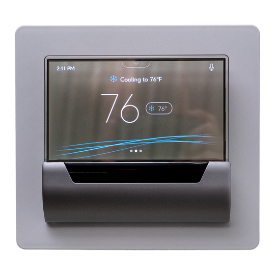
Johnson Controls GLAS User Manual
Hide thumbs
Also See for GLAS:
- Installation instructions manual (46 pages) ,
- Technical bulletin (21 pages) ,
- Quick start manual (2 pages)
Table of Contents
Advertisement
Advertisement
Table of Contents

Related Manuals for Johnson Controls GLAS


Summary of Contents for Johnson Controls GLAS
- Page 4 Can’t find what you’re looking for? Give us a call at 1-833-297-4527(GLAS) and our technical team can walk you through it. Before you start, download the GLAS app for easy installation.
- Page 5 Included in box GLAS Thermostat 4 Screws Wall Plate 4 Drywall Anchors 4 to 5 Wire Adapter Quick Start Guide Tools required Screwdriver Drill Level...
- Page 6 Compatibility GLAS is compatible with most 24 VAC heating and cooling systems. Use the compatibility checker to ensure your system will work with GLAS by going to glas.johnsoncontrols.com/compatibilitychecker. One or two stages Heating One or two stages Cooling One or two stages with one-or-two stage auxiliary heat...
- Page 7 Terminal descriptions Note: If you have only one R wire, connect to RC. Note: If you are replacing an existing thermostat, remove any jumper wires between R and RH or RC and RH. First stage of cooling or first stage heat pump Second stage of cooling command or second stage heat pump First stage of conventional heating or first stage auxiliary heat for heat pump systems...
- Page 8 Terminal descriptions Heat pump reversing valve (supports both O type and B type) Auxiliary - humidifier, dehumidifier, or ventilator 24 VAC Cool 24 VAC Hot 24 VAC Common...
- Page 9 If your thermostat is built into the wall and connected to thick wires with wire nuts, or if it is labeled 110, 120, or 240 volts, you have a high voltage system that is not compatible with the GLAS Thermostat. Do not connect your thermostat to these high voltage...
- Page 11 WARNING: Risk of Electric Shock. Disconnect the power supply before making electrical connections. Contact with components carrying hazardous voltage can cause electric shock and may result in severe personal injury or death. If you have any doubts about properly installing the device, please contact a professional installer.
- Page 12 Turn off system power 2. Turn off the power to your heating or cooling system at your breaker box to avoid electrocution or shock. 3. If you want to check your system’s pow- er, adjust the temperature on your current thermostat enough that the system switches into heating or cooling mode.
- Page 13 Check old wiring 4. Remove the front plate of your old ther- mostat and take a picture of the current wiring that shows the wire colors and con- nections. This picture will come in handy when connecting your new thermostat.
- Page 14 Connect optional 4 to 5 wire adapter Note: If you have a C-wire, skip to Step 8. If you do not have a C-wire to power your thermostat, use the included adapter to provide power. 5. Remove the cover of your furnace or air handling unit to access the control board.
- Page 15 Connect the adapter 6. In your HVAC equipment, disconnect wires from the control board and con- nect them to the open terminals on the adapter. 7. Connect the wired terminals on the oth- er side of the adapter back to the control board.
- Page 16 Disconnect your old thermostat 8. Disconnect your old thermostat and remove the backplate Note: While disconnecting your old ther- mostat, use drywall-safe tape to secure the wires and keep them from falling back into the wall.
- Page 17 Installing your GLAS 9. Remove the frontplate by pulling the top of the silver cover towards you. 10. Use a level to dry fit your GLAS and mark the wall where you plan to hang the thermostat. Then drill in the drywall anchors.
- Page 18 Attaching your GLAS 12. Loosely attach your GLAS to the wall using the included screws. 13. Use your level or the level displayed on the device to straighten the thermostat and tighten the screws. Do not overtight-...
- Page 19 Wiring your GLAS 14. Use the picture you took of your old wiring as a reference and connect the wires to the corresponding terminals on your new GLAS. See pages 25-26 for wiring exam- ples. Note: If you have auxiliary devices, such as a humidifier, dehumidifier, or ventilator,...
- Page 20 Attach the front plate 15. Make sure any access wire is flush against the wall and press the front plate until you hear a click.
- Page 21 Powering on your HVAC system 16. Return to your system switch or break- er box and turn the power back on. 17. Confirm that the detected wiring shown on the device screen is correct or tap any terminals incorrectly identified. 18.
- Page 23 WIRING DIAGRAMS NOTE: Wire colors are for reference only. Not every installation will have wires of the same color. If you are unsure on the proper installation of the unit, please contact a licensed electrician or a professional HVAC installer before attempting to install the unit.
- Page 24 Traditional Heat...
- Page 25 Traditional AC/Heat...
- Page 26 HVAC/Auxiliary Device...
- Page 27 Self-Powered Auxiliary Device...
- Page 28 Furnace-Powered Auxiliary Device An integrated auxiliary system is built into a furnace or air handler that shares the same power supply as the rest of the system and only requires a single control wire.
- Page 29 Furnace-Powered Auxiliary Device...
- Page 30 AUX) and no C terminal requires a relay pack for operation. 1. Connect the relay pack coil between the auxiliary device and C terminal on your GLAS device. 2. Connect the switch side of the relay pack to the two terminals on the AUX device.
- Page 31 2-Wire Auxiliary Device without C Terminal...
- Page 32 An auxiliary device with one C terminal that does not require a relay pack for opera- tion. 1. Connect the C terminal of the device to the C terminal on the furnace or air han- dler. 2. Connect the AUX terminal of your GLAS device to the control terminal on the auxiliary device.
- Page 33 2-Wire Auxiliary Device with C Terminal...
- Page 34 Heat Pump...
- Page 35 Dual-Stage Heat...
- Page 36 Dual-Stage Traditional AC...
- Page 37 Dual-Stage Heat and Traditional AC...
- Page 38 Dual-Stage Heat/Dual-Stage AC...
- Page 39 Traditional Heat Pump...
- Page 40 Dual-Stage Heat Pump...
- Page 41 Dual-Stage Heat Pump with Traditional Emergency Heat...
- Page 42 Traditional Heat Pump with Dual-Stage Emergency Heat...
- Page 43 Traditional Heat Pump with Traditional Emergency Heat...
- Page 44 Regulatory information to user FCC Part 15C 1. This device complies with part 15 of the FCC Rules. Operation is subject to the follow- ing two conditions: (1) This device may not cause harmful interference, and (2) this device must accept any interference received, including interference that may cause undesired operation.
- Page 45 RSS-102 and FCC Part 1.1310, RF Exposure radiation limits for the General Population / Uncontrolled Exposure. · This device shall be installed to maintain a separation distance of 20 cm from the gener- al population. Changes or modifications not expressly approved by Johnson Controls would void your authority to operate this device.