Table of Contents
Advertisement
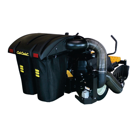
DESIGNED
TO FIT:
MODEL YEAR:
2014-Newer
COLLECTION SYSTEM
MODEL #
ALTERNATE
21120901B
MODEL #
LZ Models:
LZ 48 - 53ATDAGB050
LZ 60 - 53ANDAGD050
MANUAL PART#: Q04 5
7
GRASS COLLECTION SYSTEM
59A30045150
SZ Models:
SZ 48 - 53ATDFJB050
SZ 60 - 53ANDFJD050
OPERATOR'S MANUAL
ASSEMBLY
OPERATION
Series:
Z-Force Series
- 48", 54" & 60" DECKS
LX Models:
LX 48 - 17AIDAUB010
LX 54 - 17AIDAUC010
LX 60 - 17AIDAUD010
MAINTENANCE
PTO DRIVEN -
SX Models:
SX 48 - 17AIDGJB010
SX 54 - 17AIDGJC010
SX 60 - 17AIDGJD010
Rev: 3 - 12/12/2017
Advertisement
Table of Contents

Related Manuals for Cub Cadet 59A30045150


Summary of Contents for Cub Cadet 59A30045150
- Page 1 PTO DRIVEN - DESIGNED GRASS COLLECTION SYSTEM TO FIT: Series: MODEL YEAR: Z-Force Series 2014-Newer - 48”, 54” & 60” DECKS 59A30045150 COLLECTION SYSTEM MODEL # ALTERNATE 21120901B MODEL # LZ Models: SZ Models: LX Models: SX Models: LZ 48 - 53ATDAGB050...
-
Page 2: Table Of Contents
RESIDENTIAL BAGGING SYSTEM TABLE OF CONTENTS SECTION PAGE SECTION PAGE Safety - - - - - - - - - - - - - - - - - - - - - - - - - - - - - - 2 2-14 Length of Hose Adjustment - - - - - - - - - - - - - - 13 Safety Alert Symbols - - - - - - - - - - - - - - - - - - - - - - 3 2-15 Upper Hose Installation - - - - - - - - - - - - - - - - 13... -
Page 3: Safety Alert Symbols
SAFETY WARNING! NEVER operate the mower unless the discharge guard and either the deflector assembly or the vacuum collector adapter are fastened securely in place. WARNING! Do not work around the mower deck boot or the blower area until you are certain that the mower blades and the blower impeller have stopped rotating. -
Page 4: Warranty
PECO LIMITED WARRANTY FOR NEW PRODUCTS A. WHAT IS UNDER WARRANTY? PECO extends the following warranties to the original purchaser of each new PECO consumer product subject to the following limitations. 1. PRODUCT WARRANTY: Any part of any consumer product, which is defective in material or workmanship as delivered to the purchaser will be repaired or replaced, as PECO elects, without charge for parts or labor, if the defect appears within 12 months from the date of delivery of the product to the original purchaser. -
Page 5: Iintroduction And Description
Section I - INTRODUCTION & 2-1 Preparation Of Mower From the underside of the engine, disconnect the wiring DESCRIPTION harness attached to the electric clutch. Remove the bolt and electric clutch from the mower. Refer to Figure 2-1a. 1-1 Introduction Remove the D-drive spacer using an arbor press or Your grass collection system has been designed to give equivalent. -
Page 6: Rear Frame Bracket & Right Frame Bracket Installation
2-2 Rear Frame Bracket & Right Figure 2-2a Frame Bracket Installation Remove hardware from the rear guard assembly, shown circled in Figure 2-2A. Remove Hardware Secure the rear frame bracket P#(A1204) to the rear guard of the mower, using (4) 5/16”-18 x 1” phillips truss head zinc machine screws P#(K0504) and (4) 5/16”-18 flange nuts P#(K1178). -
Page 7: Exhaust Diverter Installation
2-3 Exhaust Diverter Installation Exhaust Clamp Kit For LZ & SZ Models Only With Round Exhaust Pipe - Attach (1) exhaust diverter P#(B0693) to the muffler Figure 2-3a Exhaust exhaust pipe. Secure the diverter using (1) exhaust Diverter clamp kit P#(X1064). Do not tighten the exhaust clamp until the PTO mount plate components have been installed and the exhaust diverter has been positioned correctly. - Page 8 2-4 PTO Mount Plate Component Installation (Cont.) Secure the PTO stiffener bracket P#(B0861) to the rear frame bracket and left and right PTO mount plates using (4) 5/16”-18 x 3/4” HHCS P#(K1153) and (4) 5/16”-18 nylon flange locknuts P#(K2516). Secure the PTO stop plate P#(B0733) to the left and right PTO mount plates using (4) 1/4”-20 x 3/4”...
-
Page 9: Pto Assembly Installation
Figure 2-6a 2-5 PTO Assembly Installation Gear Box Remove (3) 1/4”-20 x 1/2” HHSTS P#(K0353) from the Base Plate PTO assembly to remove the belt guard. Insert the mount rod of the PTO assembly P#(A1842), into the mounting slots on the PTO mount plates, as shown in Figure 2-5. -
Page 10: Lower Mount Tube Installation
2-7 Lower Mount Tube Installation Figure 2-9 Clevis Rue Ring Secure the (2) lower mount tubes P#(B0640) to the rear Cotter Pin frame bracket using (2) 5/16”-15 u-bolts P#(K1098) and Nylon Clip Flange (4) 5/16”-18 nylon flange locknuts P#(K2516) PER Locknut TUBE. -
Page 11: Blower Cone Installation
2-12 Blower Cone Installation Secure the 8” aluminum blower cone P#(E8004) to the plastic blower housing, using (3) 1/4”-20 x 3/4” HHCS P#(K1222), (3) 1/4” flat washers P#(K0037) and (3) 1/4” lock washers P#(K0039). Refer to Figure 2-12. Figure 2-12 Blower Housing 1/4”-20 x 3/4”... -
Page 12: Boot To Mower Deck Installation
Secure the boot plate assembly P#(A1961) to the 2-13 Boot To Mower Deck Installation aluminum boot P#(E0026) using (2) 3/8”-16 x 1” carriage bolts P#(K1182) and (2) 3/8”-16 nylon flange locknuts NOTE: The boot kit assembly is designed to fit the 48” P#(K2038). -
Page 13: Length Of Hose Adjustment
2-14 Length Of Hose Adjustment 2-16 Lower Hose To Blower Cone Installation The hoses in steps 2-15 and 2-16 must be cut to fit your machine. Follow steps 2-15 and 2-16. do not cut the Slide a pre-assembled hose clamp P#(J0080) over both hoses until you have tried to fit them on your machine. -
Page 14: Installation/Removal Of Collection Bags
2-18 Installation/Removal Of Figure 2-18c Plastic Top Collection Bags IMPORTANT! To prevent bag wear, install (1) Black Rubber End Cap P#(F0010), as shown in Figure 2-18a, on each Bag Ring after rotating bag 360. Bag Ring Figure 2-18a Black Rubber Connector Fasten Draw Completed Bag... -
Page 15: Weight Kit Installation
2-19 Weight Kit Installation Note: Installing a weight kit is mandatory for safe operation of the collection system. — When installing the weight bar, you should have another person to help position the weight. — If removing PTO assembly for side-discharge mowing, please also remove the weight kit. —... -
Page 16: Safety Interlock Harness Installation
LZ Model 2-20 Safety Interlock Harness Installation Figure 2-20a Current Production Model - Collection System May Require Dealer Installation! Connection Point Before installing, please verify the presence of an auxiliary 5-way male connector in the mower’s electrical harness. The connector is located underneath the operator’s seat, Early Production in front of the battery. -
Page 17: Safety Interlock Harness Wiring Diagram
P0208 Safety Interlock Wiring Harness... -
Page 18: Impeller Blade Removal/Replacement
STEP 4: Remove the blade assembly and key 2-21 Impeller Blade P#(J0254) from the PTO shaft. Removal/Replacement Note: If necessary, use a break-free agent to aid in the removal of the blade. WARNING BEFORE REMOVING/REPLACING THE IMPELLER INSTALLATION BLADES, BE SURE THE MOWER IS TURNED OFF, STEP 1: Insert the key P#(J0254) into the key way on the PTO shaft. - Page 20 A2110 Top Assembly Exploded Parts View Item # Part # Desc. Qty. V2000 Pro 2 Bagger Top / Gen. 2 V2001 Screen J4009 Short Rubber Strap w/ S-Hook K1030 1/4"-20 x 1-1/4" Carriage Bolt K0037 Flat Washer / 1/4" (.75 OD x .312 ID x .060 T) K1128 1/4"-20 Nyloc Nut K0062...
- Page 21 PTO Assembly Exploded Parts View...
- Page 22 PTO Assembly Exploded Parts View Description A1842 - PTO Item # Part # Desc. Qty. Assembly M0266 A-Section Pulley K1446 Washer (1.187 OD x .380 ID x .187 T) K1190 HHCS / 3/8"-16 x 3/4" V0015 Blower Hsg. A0429 Gear Box Assy. A1004 PTO Shaft Assy.
-
Page 23: Safety Decals
To promote safe operation, New PECO, Inc. supplies safety decals on all products manufactured. Damage can occur to safety decals either through shipment, use or reconditioning. Contact your local Service Center for replacement decals. Part# R0023 Cub Cadet Logo DANGER... -
Page 24: Operating Instructions
3-3 Disengagement Of The PTO Assy. SECTION III OPERATING INSTRUCTIONS A. To disengage the PTO assembly, slide the engagement handle out of the retaining slot and push the engagement handle away from the operator’s 3-1 General Safety seat. WARNING: The PTO assembly blades will continue to Only qualified people familiar with this operator’s manual spin. -
Page 25: Lubrication
3. Make sure all shields are in place and in good 4-2 Lubrication condition. Repair or replace any missing or damaged shields. Gearbox: 1. Every 20 hours of use: Check oil levels in gearbox. 4. Perform lubrication per paragraph 4-2. 2. -
Page 27: Notes
Notes... - Page 28 Cub Cadet LLC P.O. Box 361131 Cleveland, Ohio 44136-0019 Phone: 1-877-282-8684 MTD Products Limited Kitchener, ON N2G 4J1 1-800-668-1238...