Table of Contents
Advertisement
Quick Links
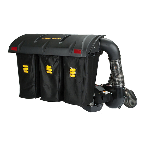
PTO GRASS
COLLECTION
SYSTEM
DESIGNED TO FIT:
2012-2013 MODEL YEAR
Cub Cadet Tank
LZ* & SZ - 48", 54" & 60" Decks
*LZ MODELS:
COLLECTION SYSTEM REQUIRES INSTALLATION
OF ADDED WEIGHT KIT 59A30037150 (A1149) FOR SAFE OPERATION!
COLLECTION SYSTEM
MODEL #: 59A30033150
(21131507)
OPERATOR'S MANUAL
ASSEMBLY OPERATION MAINTENANCE
MANUAL PART#: Q0425
REV: 5 - Jan 3rd 2018
Advertisement
Table of Contents

Related Manuals for Cub Cadet 59A30033150


Summary of Contents for Cub Cadet 59A30033150
- Page 1 LZ* & SZ - 48”, 54” & 60” Decks *LZ MODELS: COLLECTION SYSTEM REQUIRES INSTALLATION OF ADDED WEIGHT KIT 59A30037150 (A1149) FOR SAFE OPERATION! COLLECTION SYSTEM MODEL #: 59A30033150 (21131507) OPERATOR’S MANUAL ASSEMBLY OPERATION MAINTENANCE MANUAL PART#: Q0425 REV: 5 - Jan 3rd 2018...
-
Page 2: Table Of Contents
PECO GRASS COLLECTION SYSTEM TABLE OF CONTENTS SECTION PAGE SECTION PAGE Safety - - - - - - - - - - - - - - - - - - - - - - - - - - - - - - 2 2-14 Length Of Hose Adjustment - - - - - - - - - - - - - - 27 Safety Alert Symbols - - - - - - - - - - - - - - - - - - - - - - 3 2-15 Upper Hose Installation - - - - - - - - - - - - - - - - 27... -
Page 3: Safety Alert Symbols
SAFETY WARNING! NEVER operate the mower unless the discharge guard and either the deflector assembly or the vacuum collector adapter are fastened securely in place. WARNING! Do not work around the mower deck boot or the blower area until you are certain that the mower blades and the blower impeller have stopped rotating. -
Page 4: Warranty
PECO LIMITED WARRANTY FOR NEW PRODUCTS A. WHAT IS UNDER WARRANTY? PECO extends the following warranties to the original purchaser of each new PECO consumer product subject to the following limitations. 1. PRODUCT WARRANTY: Any part of any consumer product, which is defective in material or workmanship as delivered to the purchaser will be repaired or replaced, as PECO elects, without charge for parts or labor, if the defect appears within 12 months from the date of delivery of the product to the original purchaser. -
Page 5: Introduction And Description
LZ Models: Collection system requires installation of added weight kit 59A30037150 (A1149) for safe operation! SZ models do not require a weight kit. Refer to Section 2-20 in this manual for weight kit installation instructions. Contact your Cub Cadet dealer to order weight kit 59A30037150 (A1149). -
Page 6: Installation For Use
During installation, opposite from the electric clutch before continuing with the bearing inner race must be supported or bearing installation. Refer to your Cub Cadet mower owner’s damage may occur. Refer to Figure 2-1c. manual for instructions on PTO belt removal. -
Page 7: Pto Mount Plate Assembly Installation
2-2 PTO Mount Plate Assembly Installation Secure the PTO mount plate assembly P#(A1108) to the chassis of the mower using (4) 3/8”-16 x 1-14” carriage bolts P#(K1183) and (4) 3/8-16 nylon flange locknuts P#(K2038). Leave the hardware loose until the lower mount assembly is installed in the next section. -
Page 8: Pto Assembly Installation
2-4 PTO Assembly Installation Insert the PTO assembly P#(A1821) into the slots on the PTO mount plate assembly. Secure the PTO assembly with (1) mount pin P#(B0274) and (1) hair pin clip P#(K0086). Remove the belt guard P#(B0679) and hardware in preparation for the belt installation. -
Page 9: Belt Installation And Adjustment
Connect the kevlar cord belt A58K P#(M0236) from the 2-5 Belt Installation and Adjustment engine pulley to the lower gear box pulley (Figure 2-5d). Loosen the (4) bolts P#(K1191), (2) on each side, that Figure 2-5d secure the gear box assembly to the PTO assembly Connect Belt P#(A1803) (Figure 2-5a and 2-5b). -
Page 10: Cam Assembly Adjustment
2-6 Cam Assembly Adjustment The cam assembly P#(A0422), which controls the blower belt tension, comes from the factory pre-adjusted. If the belt is too tight or becomes too loose, remove the hair pin clip P#(K0099) from the belt tension rod P#(K0326) and pull the “L”... -
Page 11: Safety Interlock Harness Installation
2-8 Safety Interlock Harness Installation Route the remaining safety interlock wiring harness as shown in Figure 2-8d. Use zip ties where indicated. Remove the panel shown in Figure 2-8a in order to gain access to the mower’s safety interlock switch. Figure 2-8d Figure 2-8a Route Under... - Page 12 2-8 Safety Interlock Harness Installation for the SZ Model Remove the bracket and hardware shown in Figure 2-8g to gain access to the SZ model safety interlock switch. Use the instructions on the previous page as a reference for routing the safety interlock wiring harness from the PTO assembly to the safety interlock switch.
-
Page 13: Upper Frame Assembly Installation
2-9 Upper Frame Assembly Installation NOTE: During this step, it is suggested that two people install the upper frame to the lower mount tube. Lift the upper frame assembly P#(A1058) above the lower mount assembly and lower the top assembly onto the two vertical tubes. -
Page 14: Top Assembly To Upper Frame Assembly Installation
2-10 Top Assembly To Upper Frame Assembly Installation Position the top assembly P#(A1139) above the upper frame assembly as shown in Figure 2-10. Fasten the top assembly to the upper frame assembly using (2) 5/16”- 18 x 2-1/2” HHCS P#(K0125) and (2) 5/16”-18 nylon flange locknuts P#(K2516). -
Page 15: Deck Baffle Installation
2-12 Deck Baffle Installation A deck baffle must be installed on Select Cut model decks. Remove (1) 3/8”-16 carriage bolt and (1) 3/8”-16 nut from behind the front right caster shown in Figure 2-12a. Figure 2-12a Remove This Hardware NOTE: Some hardware has been removed from Figure 2-12b for visual clarification. -
Page 16: Boot To Mower Deck Installation
2-13 Boot To Mower Deck Installation NOTE: The aluminum boot P#(E0020) is designed to fit the 48”, 54” and 60” deck. In order to achieve a snug fit from the boot to the mower deck, the boot must be attached to the deck and positioned forward or back, upwards or down depending on the deck size. - Page 17 2-13 Boot To Mower Deck Installation Continued Step 3: Remove the 3/8”-16 carriage bolt and 3/8”-16 nut shown in Figure 2-13c. Figure 2-13c Remove Hardware Step 4: Replace the hardware removed in Step 3 with (1) 3/8”-16 x 1-1/4” carriage bolt P#(K1183) and (1) 3/8”-16 nylon flange locknut P#(K2038) as shown in Figure 2- 13d.
- Page 18 2-13 Boot To Mower Deck Installation Continued Step 4: Loosen, but DO NOT REMOVE the (1) 3/8”-16 carriage bolt and (1) 3/8”-16 nut shown in Figure 2-13e. Figure 2-13e Loosen Hardware Do Not Remove Step 5: Loosen, but DO NOT REMOVE the (1) 3/8”-16 carriage bolt and (1) 3/8”-16 nut shown in Figure 2-13f.
- Page 19 2-13 Boot To Mower Deck Installation Continued Step 6: Locate the deck mount plate P#(A1120). Lift the discharge chute and position the deck mount plate as shown in Figure 2-13g. Figure 2-13g Deck Mount Plate Step 7: Insert the deck mount plate in-between the discharge stiffener and the top of the mowing deck, aligning the front slot on the deck mount plate with the front set of hardware that was replaced in Step 4.
- Page 20 2-13 Boot To Mower Deck Installation Continued Step 8: With the front slot on the deck plate aligned with the hardware added in Step 4, push the rear portion of the deck mount plate into position so that the rear slot on the deck mount plate is aligned with the hardware that was replaced in Step 2.
- Page 21 2-13 Boot To Mower Deck Installation Continued Step 9: Locate the aluminum boot P#(E0020) and the boot plate assembly P#(A1121). Secure the boot plate assembly to the boot as shown in Figure 2-13k, using (2) 3/8”-16 x 1” carriage bolts P#(K1182) and (2) 3/8”-16 nylon flange locknuts P#(K2038).
- Page 22 2-13 Boot To Mower Deck Installation Continued Step 11: Secure the boot plate assembly to the deck mount plate using (1) boot rod P#(B0244). Insert the boot rod from the front of the deck as shown in Figure 2-13m. Figure 2-13m Slide Boot Rod Through All Four Bushings Insert Boot Rod...
- Page 23 2-13 Boot To Mower Deck Installation Continued Step 13: While holding the boott snug to the mower deck as shown in Figure 2-13n on the previous page, tighten the hardware shown in Figure 2-13o. NOTE: Tighten hardware in the following sequence only. Figure 2-13o Tighten Hardware...
- Page 24 2-13 Boot To Mower Deck Installation Continued Step 15: Tighten the hardware shown in Figure 2-13q. NOTE: (For Select-Cut Models Only) Adjust the deck baffle so that the angle on the baffle flange matches the slope on the cutting deck. Refer to Section 2-12 for reference on deck baffle positioning.
- Page 25 2-13 Boot To Mower Deck Installation Continued Step 17: While still holding the boot snug to the mower deck, tighten the lower set of hardware on the discharge chute stiffener. You can access this hardware through the boot opening shown in Figure 2-13s. Figure 2-13s Hold Boot In Position...
- Page 26 2-13 Boot To Mower Deck Installation Continued Step 19: Insert (1) hair pin clip P#(K0099) as shown in Figure 2-13u, to secure the boot rod. Figure 2-13u Insert Hair Pin Clip As Shown Step 20: Examine the boot fit-up closely. Ensure that there are no excessive gaps between the boot and the mower deck.
-
Page 27: Length Of Hose Adjustment
2-14 Length Of Hose Adjustment 2-16 Lower Hose To Blower Cone The hoses in steps 2-15 and 2-16 must be cut to fit your Installation machine. Follow steps 2-15 and 2-16. Do not cut the Slide a 8” hose clamp P#(J0080) over both ends of the hoses until you have tried to fit them on your machine. -
Page 28: Impeller Blade Removal/Replacement
2-18 Impeller Blade Removal/Replacement Tips on removing impeller blade; To gain impeller blade (#1) access, first remove the 1 - Try carefully hitting the base of the impeller blade blower cone (#2) from the blower housing, located on (#1), between each vein (#12), with a rubber mallet to the PTO assembly P#(A1821), by removing two blower loosen the taper-lock bushing hold. -
Page 29: Weight Kit Installation
2-19 Weight Kit Installation Figure 2-19c Cub Cadet 2012 Tank LZ Models - Installing a weight kit is mandatory for safe operation of the collection system. SZ models do not require a weight kit. Completely thread (2) 3/8”-16 flange nuts P#(K1215) onto (1) 3/8”-16 U-bolt P#(K0407). -
Page 30: Installation/Removal Of Collection Bags
2-20 Installation/Removal Of Figure 2-20c Collection Bags Plastic Top IMPORTANT! To prevent bag wear, install (2) red plastic end caps P#(J0274), as shown in Figure 2-20a, on each bag ring before installing bags. Figure 2-21a Bag Ring Red Plastic End Caps Fasten Draw -Latch Here &... -
Page 31: Exploded Part Views And Assemblies
3/16" x 1-1/2" FENDER WASHER, Z K1265 BLACK PANEL RETAINER V1120 SCREEN V1118 DUST GUARD R0006 CUB CADET LOGO R1057 2" x 4" Red Reflector Label R1069 Warning - Turn Off Blower Label R1065 Made In USA Label R1054 Important Check Hoses... - Page 32 Exploded Parts View A1821 PTO Assembly 3*, 4* & 5* - Are Used To Fasten Pulley To Gear Box Iso View...
- Page 33 PTO Parts List A1821 PTO Assembly Item # Doc # Title A0431 GEAR BOX A0498 PULLEY ASSY. FOR GEAR BOX K0360 7/8" SNAP RING J0272 #9 WOODRUFF KEY K0035 5/16-18 SET SCREW K0348 3/8"-16 x 2" ALL THREAD HHCS K0047 3/8"...
- Page 35 Wiring Diagram P0208 Safety Interlock Wiring Harness...
-
Page 36: Operating Instructions
SECTION III 3-3 Disengagement Of The Blower OPERATING A. To disengage the blower, rotate the engagement INSTRUCTIONS handle towards the mower. 3-1 General Safety WARNING: The blower will continue to spin. DO NOT TOUCH the blower, pulleys, or the belt until the tractor is Only qualified people familiar with this operator’s manual turned off. -
Page 37: Lubrication
ASSEMBLY and telephone number of their Service Center. Your Service Center will be happy to supply replacement MODEL: 59A30033150 parts, accessories, and do any service or repairs to your collection system. If for any reason your Service Center is unable to service your collection system or supply... -
Page 38: Safety Decals
To promote safe operation, PECO supplies safety decals on all products manufactured. Damage can occur to safety decals either through shipment, use or reconditioning. Contact your local Service Center for replacement decals. Part #: R0006 - Cub Cadet Label Part #: R1051... - Page 40 NOTES...
- Page 41 Cub Cadet LLC P.O. Box 361131 Cleveland, Ohio 44136-0019 Phone: 1-877-282-8684 MTD Products Limited Kitchener, ON N2G 4J1 1-800-668-1238...