Table of Contents
Advertisement
Advertisement
Table of Contents

Related Manuals for Delta DPM-C530A


Summary of Contents for Delta DPM-C530A
- Page 1 Multi-functional Power Meter DPM-C530A User Manual www.deltaww.com...
-
Page 2: Table Of Contents
Table of Contents 1. Preface ‧ ‧ ‧ ‧ ‧ ‧ ‧ ‧ ‧ ‧ ‧ ‧ ‧ ‧ ‧ ‧ ‧ ‧ ‧ ‧ ‧ ‧ ‧ ‧ ‧ ‧ ‧ ‧ ‧ ‧ ‧ ‧ ‧ ‧ ‧ ‧ ‧ ‧ ‧ ‧ ‧ ‧ ‧ ‧ ‧ ‧ ‧ ‧ ‧ 2 2. -
Page 3: Preface
Thank you for choosing this product. This manual offers information related to installation of the DPM-C530A power meter. Before using the meter, please read this manual carefully to ensure proper use of this meter. Also, please place the manual at an easy-to-find location for reference at any time. -
Page 4: Notes
Notes 2.1 Safety Notes Always be aware of the following safety notes when installing, wiring, operating, maintaining, and checking the device. ◆ Notes on Installation » Install the power meter according to instructions on the manual. Otherwise, damage on the device might result. -
Page 5: Installation Environment
2.2 Installation Environment Before installation, this product must be placed in its packaging box. If not used for a while, be sure to watch for the following when storing the meter, so that the product could be kept under the company's warranty coverage for future maintenance. ■... -
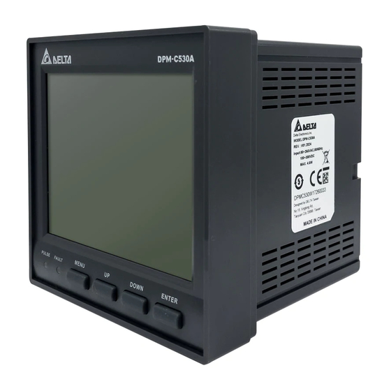
Page 6: Descriptions Of Parts
Descriptions of Parts 3.1 Operating Interface DPM-C530A uses a LCD display that exhibits four pieces of measurement information on each page. Diagram below is an illustration of the interface. Descriptions: A. Title Up key B. Area of display G. Down key C. - Page 7 ◆ Front 198*160 DOTS LCD DISPLAY MENU DOWN ENTER PULSE FAULT ◆ Back FUNCTION VOLTAGE CURRENT INPUT / OUTPUT CONNECTOR PIN ASSIGNMENT L1/+ L2/- 20V L-N ~ 400V L-N MEASURED VOTAGE 35V L-L ~ 690V L-L L1/+ 80 ~ 265 VAC L2/- CONTROL POWER 400mA MAX.
-
Page 8: Installation
Installation 4.1 Installation Method Note: ■ The installation method should be based on instructions. Otherwise, breakdown would result. ■ For better effectiveness of cooling cycles, sufficient space must be kept between adjacent objects and walls during the installation. Otherwise, imperfect cooling would result. ■... - Page 9 Dimensions of Panel Hole:...
-
Page 10: Basic Checks
4.2 Basic Checks Items Checked Contents of Checks ■ Regularly check for losing of the fixing mount at the location where the power meter and device are connected. ■ Guard against entrance of foreign objects, such as oil, water, or metal powder at General Check the heat dissipating holes. -
Page 11: Wiring Diagrams
Wiring Diagrams 5.1 Wiring on the Back This chapter illustrates how the wiring on the back is done. Note: ■ To avoid electric shock, do not alter wiring when the power is on. ■ As there is no power switch on the power meter, be sure to install a breaker switch on the power cord for the meter. -
Page 12: Descriptions Of Wiring
■ Supported Methods of Wiring: I1 - I3 - Diagram 5-1: One-phase two-wire, 1 CT Diagram 5-2: One-phase three-wire, 2 CT I3 - Diagram 5-3: Three-phase three-wire, Diagram 5-4: Three-phase three-wire, Δ Delta-connection, 3 CT, No PT Δ Delta-connection, 2 CT, No PT... - Page 13 I3 - Diagram 5-5: Three-phase three-wire, Diagram 5-6: Three-phase four-wire, Δ Delta-connection, 3 CT, 2 PT Y-connection, 3 CT, No PT I2 - I2 - I3 - I3 - Diagram 5-7: Three-phase four-wire, Diagram 5-8: Three-phase four-wire, Y-connection, 3 CT, 3 PT Y-connection, 2 CT, 3 PT ■...
-
Page 14: Panel Display And Settings
Panel Display and Settings 6.1 Panel Display 6.1.1 Area of Display DPM-C530A uses LCD display that exhibits four pieces of measurement information on each page. Diagram below is an illustration of the display panel: Descriptions: Title Area of display Pulse light... -
Page 15: Menu Tree
6.1.3 Menu Tree 1. Time, date 2. Meter information 3. Communication parameter 4.CT, PT proportion 5. System parameter 6. Alarm 7. Demand 0. Setting 8. Reset Unbalanced Unbalanced line 1. Voltage Measure Phase voltage Line voltage phase voltage % voltage % Default Unbalanced 2. -
Page 16: General Operations
6.2 General Operations 6.2.1 Observing Measured Data ■ Voltage Measurement: Parameter of voltage measured by the power meter, including phase voltage, line voltage, rate of phase voltage imbalance, rate of line voltage imbalance, etc ■ Current Measurement: Parameter of currents measured by the meter, including phase/line voltage, rate of current imbalance, etc. -
Page 17: Setup Operations
6.3 Setup Operations 6.3.1 Time and Date Settings ■ Time:Current time on the meter, including hour, Minute, second. ■ Date: Current date on the meter, including last two digits of the year, Month, Day, and day of week. ■ Steps to set up are as follows: (1) Press Menu key until the menu appears. - Page 18 (3) Select 3. Communication and press the Enter key to enter into options. (4) Select Address and press the Enter key to start setting up for the address. (5) When the option is highlighted, start setting up by using the Up and Down keys to select the numbers needed.
- Page 19 (8) When the setup is finished, other parameters could be set. The steps start from step 5 mentioned above. (9) After completing or cancelling the setup, press the Menu key again to return to the setup menu. 6.3.4 Settings for System Parameters ■...
- Page 20 (7) Setup for backlight brightness, method of wiring、CT 數、PT 數 and phase sequence reversal all follow the steps mentioned above. (8) Select Timeout and press the Enter key to start setting up for timeout. (9) When the option is highlighted, start setting up by using the Up and Down keys to select the numbers needed.
- Page 21 (10) Press the Enter key to finish setting up for a number and move on to set up for the next number. (11) Repeat steps (9)~(10) until finishing setup for the last number and press the Enter key. When the highlight disappears, setup is complete.
- Page 22 6.3.7 Restore Settings ■ Default: Restores settings on the meter to factory default. ■ Energy: Resets to zero for the value of electrical energy accumulated on the meter and that calculated without a meter-checking personnel. ■ Demand: Resets to zero for the currents calculated by the meter, value of power demand, and logged time and date.
-
Page 23: Parameters And Functions
00~60 byte second R / W Meter constant 3200 Uint P/kWh 0: None Meter model byte 1: DPM-C530A day: 0~65535 byte Total time on power hour: 00~24 hour and byte minute: 00~60 minute Firmware version number 0.0000 ~ 9.9999... - Page 24 0: 100% Screen brightness 1: 50% byte R / W 2: 25% 0: 9600, Baud Rate 1: 19200, byte R / W 2: 38400 0: ASCII Communication mode byte R / W 1: RTU 0: 8 Data bit byte R / W 1: 7 0: None Parity...
- Page 25 Pickup setpoint (currents exceeding this value(A), alarm Float R / W 0.000~99999.999 generated pickup time delay (triggering 0~99 byte R / W delayed) Dropout setpoint (currents lower 0.000~99999.999 Float R / W than this value (A), alarm cleared) Dropout time delay (restoration 0~99 byte R / W...
- Page 26 pickup time delay (triggering 0~99 byte R / W delayed) dropout setpoint (voltage exceeding this value (V), alarm 0.000~99999.999 Float R / W cleared) dropout time delay (restoration 0~99 byte R / W delayed) Alarm - Over Voltage Unbalance 0: Disable Alarm Enable byte R / W...
- Page 27 dropout setpoint (reactive power lower than this value (kVAR), 0.000~99999.999 Float kVAR R / W alarm cleared) dropout time delay (restoration 0~99 byte R / W delayed) Alarm - Over Apparent Power 0: Disable Alarm Enable byte R / W 1: Enable pickup setpoint (apparent power exceeding this value (kVA), alarm...
- Page 28 dropout time delay (restoration 0~99 byte R / W delayed) Alarm - Lag Displacement PF 0: Disable Alarm Enable byte R / W 1: Enable pickup setpoint (displacement power factor lower than this 0.000~99999.999 Float R / W value, alarm generated) pickup time delay (triggering 0~99 byte...
- Page 29 Alarm - Over Apparent Power Demand 0: Disable Alarm Enable byte R / W 1: Enable pickup setpoint (apparent power demand exceeds this value 0.000~99999.999 Float R / W (kVA), alarm generated) pickup time delay (triggering 0~99 byte R / W delayed) dropout setpoint (apparent power lower than this value (kVA), alarm...
- Page 30 pickup setpoint (current THD exceeding this value, alarm 0.000~99999.999 Float R / W generated) pickup time delay (triggering 0~99 byte R / W delayed) dropout setpoint (current THD lower than this value (kW), alarm 0.000~99999.999 Float R / W cleared) dropout time delay (restoration 0~99 byte...
- Page 31 1. Power Meter Parameters: 0100 - 01FF Phase A voltage 0.000~99999.999 Float Phase B voltage 0.000~99999.999 Float Phase C voltage 0.000~99999.999 Float Average value of phase voltage 0.000~99999.999 Float AB-line voltage 0.000~99999.999 Float BC-line voltage 0.000~99999.999 Float CA-line voltage 0.000~99999.999 Float Average value of line voltage 0.000~99999.999...
- Page 32 Phase B current 0.000~99999.999 Float Phase C current 0.000~99999.999 Float Average current on three phases 0.000~99999.999 Float Natural current 0.000~99999.999 Float Unbalanced current on phase A 0.00~99.99 Float Unbalanced current on phase B 0.00~99.99 Float Unbalanced current on phase C 0.00~99.99 Float Unbalanced current...
- Page 33 Instantaneous active power on 0.000~99999.999 Float phase A Instantaneous active power on 0.000~99999.999 Float phase B Instantaneous active power on 0.000~99999.999 Float phase C Total instantaneous reactive 0.000~99999.999 Float kVAR power Instantaneous reactive power on 0.000~99999.999 Float kVAR phase A Instantaneous reactive power on 0.000~99999.999 Float...
- Page 34 Positive active electric energy on 0x80000001 ~ 0x7FFFFFFF three phases - Opposite active (negative for 2’s complement) electric energy on three phases Positive reactive electric energy on three phases + Opposite 0x00000000~0xFFFFFFFF Uint VARh reactive electric energy on three phases Positive reactive electric energy on three phases - Opposite 0x80000001 ~ 0x7FFFFFFF...
- Page 35 Present demand for current on 0.000 ~ 99999.999 Float three phases Previous average demand for 0.000 ~ 99999.999 Float current on three phases Estimated required current for 0.000 ~ 99999.999 Float 3-phase balance Peak demand for current on three 0.000 ~ 99999.999 Float phases year: 00~99...
- Page 36 hour: 00~24 byte hour minute minute: 00~60 Time of peak demand for positive reactive power on three phases second: 00~60 byte second Present demand for positive 0.000 ~ 99999.999 Float apparent power on three phases Previous demand for positive 0.000 ~ 99999.999 Float apparent power on three phases Estimated peak value of 3-phase...
- Page 37 year: 00~99 byte year month month: 1~12 Date for maximum value of voltage on line BC day: 1~31 byte hour: 00~24 byte hour minute minute: 00~60 Time for maximum value of voltage on line BC second: 00~60 byte second Maximum value of voltage on line 0.000 ~ 99999.999 Float year: 00~99...
- Page 38 Maximum value of current on 0.000 ~ 99999.999 Float phase B year: 00~99 byte year month month: 1~12 Date for maximum value of current on phase B day: 1~31 byte hour: 00~24 byte hour minute minute: 00~60 Time for maximum value of current on phase B second: 00~60 byte...
- Page 39 hour: 00~24 byte hour minute minute: 00~60 Time for maximum value of total active power second: 00~60 byte second Maximum value of total reactive 0.000 ~ 99999.999 Float kVAR power year: 00~99 byte year month month: 1~12 Date for maximum value of total reactive power day: 1~31 byte...
- Page 40 year: 00~99 Date for maximum value of total byte year month month: 1~12 harmonic distortion for voltage on phase A day: 1~31 byte hour: 00~24 byte hour minute Time for maximum value of total minute: 00~60 harmonic distortion for voltage on phase A second: 00~60 byte...
- Page 41 Maximum value of total harmonic 0.00 ~ 99.99 Float distortion for current on phase B year: 00~99 byte year month Date for maximum value of total month: 1~12 harmonic distortion for current on phase B day: 1~31 byte hour: 00~24 Time for maximum value of total byte hour minute...
- Page 42 hour: 00~24 byte hour minute minute: 00~60 Time for maximum value of voltage unbalance on line CA second: 00~60 byte second Maximum value of voltage 0.00 ~ 99.99 Float unbalance on phase A year: 00~99 byte year month month: 1~12 Date for maximum value of voltage unbalance on phase A day: 1~31...
- Page 43 year: 00~99 byte year month month: 1~12 Date for maximum value of current unbalance on phase A day: 1~31 byte hour: 00~24 byte hour minute minute: 00~60 Time for maximum value of current unbalance on phase A second: 00~60 byte second Maximum value of current 0.00 ~ 99.99...
- Page 44 hour: 00~24 byte hour minute minute: 00~60 Time for minimum value of voltage on line BC second: 00~60 byte second Minimum value of voltage on line 0.000 ~ 99999.999 Float year: 00~99 byte year month month: 1~12 Date for minimum value of voltage on line CA day: 1~31 byte...
- Page 45 year: 00~99 byte year month month: 1~12 Date for minimum value of current on phase B day: 1~31 byte hour: 00~24 byte hour minute minute: 00~60 Time for minimum value of current on phase B second: 00~60 byte second Minimum value of current on 0.000 ~ 99999.999 Float phase C...
- Page 46 Minimum value of total reactive 0.000 ~ 99999.999 Float kVAR power year: 00~99 byte year month Date for minimum value of total month: 1~12 reactive power day: 1~31 byte hour: 00~24 byte hour minute minute: 00~60 Time for minimum value of total reactive power second: 00~60 byte...
- Page 47 hour: 00~24 byte hour minute Time for minimum value of total minute: 00~60 harmonic distortion for voltage on phase A second: 00~60 byte second Minimum value of total harmonic 0.000~999.999 Float distortion for voltage on phase B year: 00~99 byte year month Date for minimum value of total month: 1~12...
- Page 48 year: 00~99 byte year month Date for minimum value of total month: 1~12 harmonic distortion for current on phase B day: 1~31 byte hour: 00~24 Time for minimum value of total byte hour minute minute: 00~60 harmonic distortion for current on phase B second: 00~60 byte...
- Page 49 Minimum value of voltage 0.00~99.99 Float unbalance on phase A year: 00~99 byte year month Date for minimum value of voltage month: 1~12 unbalance on phase A day: 1~31 byte hour: 00~24 byte hour minute minute: 00~60 Time for minimum value of voltage unbalance on phase A second: 00~60 byte...
- Page 50 hour: 00~24 byte hour minute minute: 00~60 Time for minimum value of current unbalance on phase A second: 00~60 byte second Minimum value of current 0.00~99.99 Float unbalance on phase B year: 00~99 byte year month month: 1~12 Date for minimum value of current unbalance on phase B day: 1~31 byte...
- Page 51 4. Alarm: 0400 ~ 04FF 00 ~ FF (high byte, category) alarm 01 00 ~ FF (high byte, number of times) 00 ~ FF (high byte, category) alarm 02 00 ~ FF (high byte, number of times) 00 ~ FF (high byte, category) 00 ~ FF alarm 03 (high byte, number of times) 1.
- Page 52 00 ~ FF (high byte, category) alarm 25 1. over current 00 ~ FF (high byte, number of times) 2. under current 00 ~ FF (high byte, category) 3. over mid line voltage alarm 26 00 ~ FF (high byte, number of times) 4.
- Page 53 year: 00~99 byte year month month: 1~12 alarm 04 date day: 1~31 byte hour: 00~24 byte hour minute minute: 00~60 alarm 04 time second: 00~60 byte second year: 00~99 byte year month month: 1~12 alarm 05 date day: 1~31 byte hour: 00~24 byte hour minute...
- Page 54 year: 00~99 byte year month month: 1~12 alarm 12 date day: 1~31 byte hour: 00~24 byte hour minute minute: 00~60 alarm 12 time second: 00~60 byte second year: 00~99 byte year month month: 1~12 alarm 13 date day: 1~31 byte hour: 00~24 byte hour minute...
- Page 55 year: 00~99 byte year month month: 1~12 alarm 20 date day: 1~31 byte hour: 00~24 byte hour minute minute: 00~60 alarm 20 time second: 00~60 byte second year: 00~99 byte year month month: 1~12 alarm 21 date day: 1~31 byte hour: 00~24 byte hour minute...
- Page 56 year: 00~99 byte year month month: 1~12 alarm 28 date day: 1~31 byte hour: 00~24 byte hour minute minute: 00~60 alarm 28 time second: 00~60 byte second year: 00~99 byte year month month: 1~12 alarm 29 date day: 1~31 byte hour: 00~24 byte hour minute...
- Page 57 year: 00~99 byte year month month: 1~12 alarm 36 date day: 1~31 byte hour: 00~24 byte hour minute minute: 00~60 alarm 36 time second: 00~60 byte second year: 00~99 byte year month month: 1~12 alarm 37 date day: 1~31 byte hour: 00~24 byte hour minute...
- Page 58 year: 00~99 byte year month R / W month: 1~12 Auto recording 2, ending date setting day: 1~31 byte R / W Block transfer 1 setting 0x0100~0x01C7 R / W Block transfer 2 setting 0x0100~0x01C7 R / W … …. 0x0100~0x01C7 R / W Block transfer 70 setting...
- Page 59 Phase C voltage with 11 harmonic Float component 0.000~999.999 0707 Float 0.000~999.999 Phase C voltage with 21 harmonic Float component 0.000~999.999 0708 Float 0.000~999.999 Phase C voltage with 31 harmonic Float component 0.000~999.999 Phase A current with 1 harmonic Float component 0.000~999.999 0709...
- Page 60 Average current Float Mid-line current Float Power factor Float Displacement power factor Float Total active power Float Total reactive power Float Total apparent power Float Positive direction active power Uint Reversed direction active power Uint Positive direction reactive power Uint Reversed direction reactive power Uint Positive direction apparent power...
- Page 61 0DA2 data log min 2 hour 0 day2 … … data log min 59 hour 0 day2 data log min 0 hour 1 day2 data log min 1 hour 1 day2 data log min 2 hour 1 day2 ...
- Page 62 B084 data log min 0 hour 23 day30 B085 data log min 1 hour 23 day30 B086 data log min 2 hour 23 day30 … … B0BF data log min 59 hour 23 day30 B0C0 data log min 0 hour 0 day31 ...
- Page 63 0817 data log min 55 hour 1 day1 0818 data log min 0 hour 2 day1 0819 data log min 5 hour 2 day1 081A data log min 10 hour 2 day1 … … 0823 data log min 55 hour 2 day1 ...
- Page 64 29C2 data log min 10 hour 0 day31 … … 29CB data log min 55 hour 0 day31 29CC data log min 0 hour 1 day31 29CD data log min 5 hour 1 day31 29CE data log min 10 hour 1 day31 ...
- Page 65 4B74 data log min 0 hour 23 day60 4B75 data log min 5 hour 23 day60 4B76 data log min 10 hour 23 day60 … … 4B7F data log min 55 hour 23 day60 4B80 data log min 0 hour 0 day61 ...
- Page 66 4CB8 data log min 0 hour 2 day62 4CB9 data log min 5 hour 2 day62 4CBA data log min 10 hour 2 day62 … … 4CC3 data log min 55 hour 2 day62 … …...
- Page 67 … … 1855 data log min 50 hour 0 day30 1856 data log min 0 hour 1 day30 1857 data log min 10 hour 1 day30 1858 data log min 20 hour 1 day30 … …...
- Page 68 … … 196F data log min 50 hour 23 day31 … … 2930 data log min 0 hour 0 day60 2931 data log min 10 hour 0 day60 2932 data log min 20 hour 0 day60 ...
- Page 69 … … 29D1 data log min 50 hour 2 day61 … … 2A4A data log min 0 hour 23 day61 2A4B data log min 10 hour 23 day61 2A4C data log min 20 hour 23 day61 ...
- Page 70 082E data log min 0 hour 23 day1 082F data log min 30 hour 23 day1 … … 0D70 data log min 0 hour 0 day30 0D71 data log min 30 hour 0 day30 0D72 data log min 0 hour 1 day30 ...
- Page 71 1345 data log min 30 hour 2 day61 … … 136E data log min 0 hour 23 day61 136F data log min 30 hour 23 day61 1470 data log min 0 hour 0 day62 1471 data log min 30 hour 0 day62 ...
- Page 72 0DA0 data log min 0 hour 0 day61 0DA1 data log min 30 hour 0 day61 0DA2 data log min 0 hour 1 day61 … … 0DB7 data log min 30 hour 23 day61 0DB8 data log min 0 hour 0 day62 ...
-
Page 73: Messages Of Abnormal Operations
Messages of Abnormal Operations Under abnormal communications, the power meter can send out messages via Modbus (codes shown below), informing the reason why the main station experienced abnormal situation. Abnormal Message Code Name Description 0x01 Illegal Function Illegal functional code 0x02 Illegal Data Address Address of data read or written is illegal... - Page 74 Over active power demand Total active power demand is higher than alert value Over reactive power demand Total reactive power demand is higher than alert value Over apparent power demand Total apparent power demand is higher than alert value Over-frequency System frequency is higher than alert value Low frequency System frequency is lower than alert value...
-
Page 75: Specifications
Specifications 9.1 Specifications Feature Model Name DPM-C530A Phase voltage √ Line voltage √ Phase current √ Line current √ Measurement Active power √ Parameters Reactive power √ Apparent power √ Power factor √ Frequency √ Real energy √ Reactive energy √... - Page 76 Total harmonics in voltage ±1% Harmonics ±1% Frequency Accuracy ±0.5% One-phase two-wire, 1CT One-phase three-wire, 2CT Three-phase three-wire, Δ Delta- connection, 3CT, No PT Three-phase three-wire, Δ Delta- connection, 2CT, No PT Three-phase three-wire, Δ Delta- Wiring Method connection, 3CT, 2PT Three-phase four-wire,...
-
Page 77: Communication Specifications
Modbus RTU / ASCII Communication Interface RS485 Interface Baud Rate 9600/19200/38400 bps Dimensions (Width x Height x Depth) 96 x 96 x 95.4 mm Exterior IP52 (front panel), IP20 (meter IP Protections body) Operating Temperature -20℃ ~ +70℃ Storage Temperature -30℃... -
Page 78: Modbus Communication
9.3 Modbus Communication 9.3.1 Format of Modbus Communication: Function Code Modbus Name Description 0x03 Read Holding Registers Read the contents of read location 0x06 Preset Single Register Preset the contents of written location 0xFE Read Data Log Read the contents of data log 9.3.2 Modbus Communication Protocols (1) Modbus RTU mode is adopted with Modbus Master sending out the Request, in which the Function Code uses 0x03 to request response from Slave to correspond to values in Modbus address. - Page 79 Write in: Master Slave Request Response Request Response Slave Address 1 ~ 255 Slave Address 1 ~ 255 Function Code Function Code Start Address (High) 00h ~ FFh Start Address (High) 00h ~ FFh Start Address (Low) 00h ~ FFh Start Address (Low) 00h ~ FFh Number of Point (High)
- Page 80 Should Modbus Slave (power meter) receive an abnormal Request, the format of the abnormal packet responded is as follows. Refer to Chapter 9 for the abnormal codes. Slave Response Slave Address Function Code Exception Code 0x01 0x83 9.3.3 User-defined Communication Protocol for Data Log Reading (1) Take an approach similar to Modbus RTU mode.
- Page 81 Sequential order item Data size(byte) Sequential order Year Month Hour Minute second High byte Low word Low byte Average phase voltage(V) High byte High word Low byte High byte Low word Low byte Average line voltage(V) High byte High word Low byte High byte Low word...
- Page 82 Sequential order item Data size(byte) Sequential order High byte Low word Low byte Reactive power(kVAR) High byte High word Low byte High byte Low word Low byte Apparent power(kVA) High byte High word Low byte High byte Low word Low byte Positive active energy (Wh) High byte...
-
Page 83: Appendix
Appendix Appendix 1: Selecting Accessories Current Transformer: Should input current exceed rated current tolerated by the meter specifications, the power meter needs to be used together with a current transformer (CT). Users can select a suitable CT according to the table below. - Page 84 Delta Electronics (Korea), Inc. 1511, Byucksan Digital Valley 6-cha, Gasan-dong, Geumcheon-gu, Seoul, Korea, 153-704 TEL: 82-2-515-5303 / FAX: 82-2-515-5302 Delta Electronics Int’l (S) Pte Ltd 4 Kaki Bukit Ave 1, #05-05, Singapore 417939 TEL: 65-6747-5155 / FAX: 65-6744-9228 Delta Electronics (India) Pvt. Ltd.