Table of Contents
Advertisement
Quick Links
Industrial Automation Headquarters
Delta Electronics, Inc.
Taoyuan Technology Center
No.18, Xinglong Rd., Taoyuan District,
Taoyuan City 33068, Taiwan
TEL: 886-3-362-6301 / FAX: 886-3-371-6301
Asia
Delta Electronics (Shanghai) Co., Ltd.
No.182 Minyu Rd., Pudong Shanghai, P.R.C.
Post code : 201209
TEL: 86-21-6872-3988 / FAX: 86-21-6872-3996
Customer Service: 400-820-9595
Delta Electronics (Japan), Inc.
Tokyo Office
Industrial Automation Sales Department
2-1-14 Shibadaimon, Minato-ku
Tokyo, Japan 105-0012
TEL: 81-3-5733-1155 / FAX: 81-3-5733-1255
Delta Electronics (Korea), Inc.
Seoul Office
1511, 219, Gasan Digital 1-Ro., Geumcheon-gu,
Seoul, 08501 South Korea
TEL: 82-2-515-5305 / FAX: 82-2-515-5302
Delta Energy Systems (Singapore) Pte Ltd.
4 Kaki Bukit Avenue 1, #05-04, Singapore 417939
TEL: 65-6747-5155 / FAX: 65-6744-9228
Delta Electronics (India) Pvt. Ltd.
Plot No.43, Sector 35, HSIIDC Gurgaon,
PIN 122001, Haryana, India
TEL: 91-124-4874900 / FAX : 91-124-4874945
Delta Electronics (Thailand) PCL.
909 Soi 9, Moo 4, Bangpoo Industrial Estate (E.P.Z),
Pattana 1 Rd., T.Phraksa, A.Muang,
Samutprakarn 10280, Thailand
TEL: 66-2709-2800 / FAX : 662-709-2827
Delta Energy Systems (Australia) Pty Ltd.
Unit 20-21/45 Normanby Rd., Notting Hill Vic 3168, Australia
TEL: 61-3-9543-3720
Americas
Delta Electronics (Americas) Ltd.
Raleigh Office
P.O. Box 12173, 5101 Davis Drive,
Research Triangle Park, NC 27709, U.S.A.
TEL: 1-919-767-3813 / FAX: 1-919-767-3969
Delta Greentech (Brasil) S/A
São Paulo Office
Rua Itapeva, 26 – 3˚ Andar - Bela Vista
CEP: 01332-000 – São Paulo – SP - Brasil
TEL: 55-11-3530-8642 / 55-11-3530-8640
Delta Electronics International Mexico S.A. de C.V.
Mexico Office
Vía Dr. Gustavo Baz No. 2160, Colonia La Loma,
54060 Tlalnepantla Estado de Mexico
TEL: 52-55-2628-3015 #3050/3052
*We reserve the right to change the information in this manual without prior notice.
EMEA
Headquarters:
Delta Electronics (Netherlands) B.V.
Sales: Sales.IA.EMEA@deltaww.com
Marketing: Marketing.IA.EMEA@deltaww.com
Technical Support: iatechnicalsupport@deltaww.com
Customer Support: Customer-Support@deltaww.com
Service: Service.IA.emea@deltaww.com
TEL: +31(0)40 800 3800
BENELUX:
Delta Electronics (Netherlands) B.V.
De Witbogt 20, 5652 AG Eindhoven, The Netherlands
Mail: Sales.IA.Benelux@deltaww.com
TEL: +31(0)40 800 3800
DACH:
Delta Electronics (Netherlands) B.V.
Coesterweg 45, D-59494 Soest, Germany
Mail: Sales.IA.DACH@deltaww.com
TEL: +49(0)2921 987 0
France:
Delta Electronics (France) S.A.
ZI du bois Challand 2, 15 rue des Pyrénées,
Lisses, 91090 Evry Cedex, France
Mail: Sales.IA.FR@deltaww.com
TEL: +33(0)1 69 77 82 60
Iberia:
Delta Electronics Solutions (Spain) S.L.U
Ctra. De Villaverde a Vallecas, 265 1º Dcha Ed.
Hormigueras – P.I. de Vallecas 28031 Madrid
TEL: +34(0)91 223 74 20
C/Llull, 321-329 (Edifici CINC) | 22@Barcelona, 08019 Barcelona
Mail: Sales.IA.Iberia@deltaww.com
TEL: +34 93 303 00 60
Italy:
Delta Electronics (Italy) S.r.l.
Ufficio di Milano Via Senigallia 18/2 20161 Milano (MI)
Piazza Grazioli 18 00186 Roma Italy
Mail: Sales.IA.Italy@deltaww.com
TEL: +39 02 64672538
Russia:
Delta Energy System LLC
Vereyskaya Plaza II, office 112 Vereyskaya str.
17 121357 Moscow Russia
Mail: Sales.IA.RU@deltaww.com
TEL: +7 495 644 3240
Turkey:
Delta Greentech Elektronik San. Ltd. Sti. (Turkey)
Şerifali Mah. Hendem Cad. Kule Sok. No:16-A
34775 Ümraniye – İstanbul
Mail: Sales.IA.Turkey@deltaww.com
TEL: + 90 216 499 9910
GCC:
Delta Energy Systems AG (Dubai BR)
P.O. Box 185668, Gate 7, 3rd Floor, Hamarain Centre
Dubai, United Arab Emirates
Mail: Sales.IA.MEA@deltaww.com
TEL: +971(0)4 2690148
Egypt + North Africa:
Delta Electronics
511 Cairo Business Plaza, North 90 street,
New Cairo, Cairo, Egypt
Mail: Sales.IA.MEA@deltaww.com
DPM-093AB20-02
2019/05/25
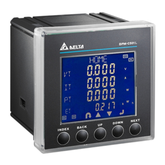
DI/DO type Power Meter
DPM-C501L / C502
Operation Manual
www.deltaww.com
Advertisement
Table of Contents

Related Manuals for Delta DPM-C501L


Summary of Contents for Delta DPM-C501L
- Page 1 Raleigh Office TEL: +7 495 644 3240 P.O. Box 12173, 5101 Davis Drive, Turkey: Delta Greentech Elektronik San. Ltd. Sti. (Turkey) Research Triangle Park, NC 27709, U.S.A. Şerifali Mah. Hendem Cad. Kule Sok. No:16-A TEL: 1-919-767-3813 / FAX: 1-919-767-3969 34775 Ümraniye – İstanbul Delta Greentech (Brasil) S/A Mail: Sales.IA.Turkey@deltaww.com...
- Page 2 DPM-C501L/C502 Operation Manual Revision History Ve r s i o n R e v i s i o n D a t e T h e f i r s t v e r s i o n w a s p u b l i s h e d .
-
Page 3: Table Of Contents
DPM-C501L/C502 Operation Manual Table of Contents Chapter 1 Product Introduction Preface ....................1-2 Overview ................... 1-2 Safety Precautions ................1-3 Chapter 2 Product Specifications Electrical Characteristics ..............2-2 Communications ................2-3 Operating the Display ................ 2-4 2.3.1 Menu Tree ..................2-5 Dimension .................. - Page 4 4.2.4 Current Transformer Setup (CT) ............4-4 4.2.5 Potential Transformer Setup (PT) ............ 4-5 4.2.6 Reset (RST) ................. 4-5 4.2.7 Digital Input (DI) ................4-6 4.2.8 Relay Output (RO) ................ 4-6 4.2.9 Edit Password (PWD) ..............4-9 4.2.10 Meter Information (INFO) .............. 4-9 Power Analysis Values ...............
-
Page 5: Chapter 1 Product Introduction
Chapter 1 Product Introduction Table of Contents Preface ....................1-2 Overview ................... 1-2 Safety Precautions ................1-3 1 - 1... -
Page 6: Preface
Delta Electronics website (http://www.delta.com.tw/ia/). Overview DPM-C501L and DPM-C502 are equipped with a large, back-lit LCD display, up to four lines of information can be displayed in this design. DPM-C501L ... -
Page 7: Safety Precautions
Cha p ter 1 P r o d u c t I n t r o d u c t i o n DPM-C502 Safety Precautions Notes on Installation Install the power meter according to instructions on the manual. Apply appropriate personal protective equipment (PPE) and follow safe electrical work practices. - Page 8 D P M - C 5 0 1 L / C 5 0 2 O p e r a t i o n M a n u a l Notes on Wiring When measured current is higher than the rated specification for the device, use of ...
-
Page 9: Chapter 2 Product Specifications
Product Specifications Chapter 2 Table of Contents Electrical Characteristics ..............2-2 Communications Specifications ............2-3 Operating the Display ................2-4 2.3.1 Menu Tree ..................2-5 Dimension ................... 2-6 DI/DO ....................2-8 2 - 1... -
Page 10: Electrical Characteristics
Rated Voltage Phase voltage: 20 to 400 VAC (L-N) Rated Current 1A / 5A Frequency 50/60 Hz Total voltage / current harmonic DPM-C501L distortion in average Harmonic Individual voltage / current harmonic DPM-C502 distortion in average Voltage Input Measuring Category: CAT III... -
Page 11: Communications
C h a p t e r 2 P r o d u c t Sp e c i f i c a t i o n MODBUS-RTU Communication RS-485 port Baud rate 9600 / 19200 / 38400 bps Dimension (W x H x D) 96 * 96 * 91.8 mm Mechanical Characteristics... -
Page 12: Operating The Display
D P M - C 5 0 1 L / C 5 0 2 O p e r a t i o n M a n u a l Operating the Display Enable / Disable UP Key Screen Title DOWN Key Load percentage NEXT Key Item... -
Page 13: Menu Tree
C h a p t e r 2 P r o d u c t Sp e c i f i c a t i o n 2.3.1 Menu Tree Display Menu Tree You can always use this button to return to HOME. -
Page 14: Dimension
D P M - C 5 0 1 L / C 5 0 2 O p e r a t i o n M a n u a l Dimension Front Unit: mm Back: 2 - 6... - Page 15 C h a p t e r 2 P r o d u c t Sp e c i f i c a t i o n Function Voltage Current 20V L-N ~ 400V L-N Rated voltage 35V L-L ~ 690V L-L 80 ~ 265 VAC Control power 400 mA MAX...
-
Page 16: Di/Do
D P M - C 5 0 1 L / C 5 0 2 O p e r a t i o n M a n u a l DI/DO Digital Input (DI) Connector type Removable Terminal Block Number of inputs 4 (dry contact) Galvanic isolation 4000 VAC 1 min... - Page 17 C h a p t e r 2 P r o d u c t Sp e c i f i c a t i o n Wiring Descriptions 250 mA fuse: Either positive or negative charge can be used on L1/+ and L2/-. When using a neutral wire for AC power, ※...
- Page 18 D P M - C 5 0 1 L / C 5 0 2 O p e r a t i o n M a n u a l MEMO 2 - 1 0...
-
Page 19: Chapter 3 Installation
Chapter 3 Installation Table of Contents Installation ..................3-2 3.1.1 Installation Environment ..............3-2 3.1.2 Notes on Installation ..............3-2 Basic Checks ..................3-4 Wiring ....................3-4 3.3.1 Wiring Diagrams ................3-4 3.3.2 DI / DO Connection ............... 3-6 3.3.3 Communication Characteristics............3-7 3 - 1... -
Page 20: Installation Environment
D P M - C 5 0 1 L / C 5 0 2 O p e r a t i o n M a n u a l 3.1 Installation 3.1.1 Installation Environment The product should be kept in the shipping carton before installation. In order to retain the warranty coverage, the product should be stored properly when it is not to be used for an extended period of time. - Page 21 C h a p t e r 3 I n s t a l l a t i o n Installation The package of this multi-functional power meter comes with securing brackets for easier mounting and removing. Dimensions of the mounting hole is 92 mm * 92 mm (see the figure below) Slide the securing bracket into the slot and then push the meter in.
-
Page 22: Basic Checks
D P M - C 5 0 1 L / C 5 0 2 O p e r a t i o n M a n u a l 3.2 Basic Checks Items Contents Regularly check for losing of the fixing mount at the location where the power meter and device are connected. - Page 23 C h a p t e r 3 I n s t a l l a t i o n Connection 3PH3W, Δ connection, 3 CT, No PT 3PH3W, Δ connection, 2 CT, No PT 3PH3W, Δ connection, 3 CT, 2 PT 3PH4W, Y connection, 3 CT, No PT 3PH4W, Y connection, 3 CT, 3 PT 3PH4W, Y connection, 2 CT, 3 PT...
-
Page 24: Di / Do Connection
D P M - C 5 0 1 L / C 5 0 2 O p e r a t i o n M a n u a l The following symbols are used in the diagram: Symbol Current Terminal Voltage Description Grounding... -
Page 25: Communication Characteristics
C h a p t e r 3 I n s t a l l a t i o n 3.3.3 Communication Characteristics Communications Specifications: Max. Communication Baud Rate 1200 m 9600, 19200, 38400 Distance Max. Connection Data Length Number Communication Parity... - Page 26 D P M - C 5 0 1 L / C 5 0 2 O p e r a t i o n M a n u a l MEMO 3 - 8...
-
Page 27: Chapter 4 Operation
Chapter 4 Operation Table of Contents General Operation ................4-2 4.1.1 Setting Menu ................4-2 Setups ....................4-3 4.2.1 Password Setup (PASS) ..............4-3 4.2.2 Communication Setup (COM) ............4-3 4.2.3 System Setup (SYS) ..............4-4 4.2.4 Current Transformer Setup (CT) ............4-4 4.2.5 Potential Transformer Setup (PT) ............. -
Page 28: General Operation
D P M - C 5 0 1 L / C 5 0 2 O p e r a t i o n M a n u a l 4.1 General Operation Use UP and DOWN keys to switch among setting pages. You can go back to HOME page by using BACK or INDEX keys. -
Page 29: Setups
C h a p t e r 4 O p e r a t i o n Reversed apparent energy page (-VAH): reversed apparent energy measured by the power meter, including reserved apparent energy (SH). Total harmonic distortion of current page (THD I): current harmonic distortion measured by the power meter, including harmonic distortion for phase A current (A), harmonic distortion for phase B current (B), harmonic distortion for phase C current (C) and total harmonic distortion for current (T). -
Page 30: System Setup (Sys)
D P M - C 5 0 1 L / C 5 0 2 O p e r a t i o n M a n u a l When the option starts blinking, you can use UP and DOWN keys to select the parity you need. Press NEXT key to confirm the setting. -
Page 31: Potential Transformer Setup (Pt)
C h a p t e r 4 O p e r a t i o n secondary-side current transformer. Press NEXT key to confirm the setting. Note: You can go back to the previous setting item by pressing BACK key anytime, whether you have completed or canceled the setting. -
Page 32: Digital Input (Di)
D P M - C 5 0 1 L / C 5 0 2 O p e r a t i o n M a n u a l Steps: Press NEXT key till the option starts blinking. Use UP and DOWN keys to select the reset options. Press NEXT key to confirm the setting. - Page 33 C h a p t e r 4 O p e r a t i o n Descriptions on the LCD display items of the relay output LCD display Item Description Disable This function is disabled. If the over-current alarm is triggered, the corresponding relay is short- circuit.
- Page 34 D P M - C 5 0 1 L / C 5 0 2 O p e r a t i o n M a n u a l If the over apparent power alarm is triggered, the corresponding relay is short- Over apparent circuit.
-
Page 35: Edit Password (Pwd)
C h a p t e r 4 O p e r a t i o n 4.2.9 Edit Password (PWD) Edit the password (default 0000) Steps: Press NEXT key till the first digit starts blinking Use UP and DOWN keys to select the first digit of the password Press NEXT key to confirm the setting and start to set the next digital input. - Page 36 D P M - C 5 0 1 L / C 5 0 2 O p e r a t i o n M a n u a l Last demand: the power meter calculates the value when the last interval completes. ...
-
Page 37: Auto-Wiring (Only Available For Dpm-C502)
C h a p t e r 4 O p e r a t i o n 4.4 Auto-wiring (only available for DPM-C502) This is a future function for DPM-C502. It will be available when the DPMSoft V1.26.8 is ready. When the CT polarity (negative and positive) is incorrectly wired, DPM-C502 treats the wiring as a correct one. -
Page 38: Chapter 5 Parameters And Funcitons
Chapter 5 Parameters and Functions Table of Contents Advanced Features ................5-2 Overview of Parameters ..............5-2 5 - 1... -
Page 39: Advanced Features
D PM -C50 1L /C 502 Ope ra tion Man ua l 5.1 Advanced Features DPM-C501L: Harmonic measurements, including voltage and current harmonics. DPM-C502: Harmonic measurements, including voltage and current harmonics. Features such as 1-31 levels of harmonic measurements, data log, time of use measurement, demand value measurement are also included. - Page 40 Ch ap te r 5 Para me ters a nd Func tio ns 40010 Firmware version 0.0000 - 9.9999 uint Year: 00-99 Year, 40011 byte Month Month: 1-12 Firmware release date 40012 Date: 1-31 word Date 40013 Reserved 0: 3φ4W 1: 3φ3W 40014 Power system configuration...
- Page 41 D PM -C50 1L /C 502 Ope ra tion Man ua l Available for C501L: V1.0006 or later 40022 Reserved 0: 9600 40023 Baud Rate 1: 19200 word 2: 38400 40024 Communication mode 1: RTU word 40025 Data bit 0: 8 word 0: None 40026...
- Page 42 Ch ap te r 5 Para me ters a nd Func tio ns Demand time interval 40031 1 – 60 word Minute (Available for C502 only) Alarm - Over Current 0:Disable 40032 Alarm Enable word 1:Enable 40033 Pickup setpoint (current value exceeding this value;...
- Page 43 D PM -C50 1L /C 502 Ope ra tion Man ua l value; alarm triggered) 40063 Reserved 40064 Dropout setpoint (line voltage value exceeding 0.000 - 99999.999 float 40065 this value; alarm cleared) 40066 Reserved Alarm - Over Voltage L-N 0: Disable 40067 Alarm Enable word...
- Page 44 Ch ap te r 5 Para me ters a nd Func tio ns Alarm - Over Active Power 0: Disable 40095 Alarm Enable word 1: Enable 40096 Pickup setpoint (total active power value exceeding this 0.000 - 99999.999 float 40097 value;...
- Page 45 D PM -C50 1L /C 502 Ope ra tion Man ua l triggered) 40112 Reserved 40113 Dropout setpoint (total apparent power value 0.000 - 99999.999 float below this value; alarm 40114 cleared) 40115 Reserved Alarm - Over Frequency 0: Disable 40172 Alarm Enable word 1: Enable...
- Page 46 Ch ap te r 5 Para me ters a nd Func tio ns 40185 Reserved 1. Meter Parameters: 0100 - 01FF 40257 Phase A voltage 0.000 - 99999.999 float 40258 40259 Phase B voltage 0.000 - 99999.999 float 40260 40261 Phase C voltage 0.000 - 99999.999 float...
- Page 47 D PM -C50 1L /C 502 Ope ra tion Man ua l 40279 Phase voltage unbalance 0.00 - 99.99 float 40280 40281 A-B line voltage unbalance 0.00 - 99.99 float 40282 40283 B-C line voltage unbalance 0.00 - 99.99 float 40284 40285 C-A line voltage unbalance 0.00 - 99.99...
- Page 48 Ch ap te r 5 Para me ters a nd Func tio ns 40303 Phase C current unbalance 0.00 - 99.99 float 40304 40305 Current unbalance 0.00 - 99.99 float 40306 40307 -1.00000 - 1.00000 Total power factor float (positive: lag; negative: lead) 40308 40309 -1.00000 - 1.00000...
- Page 49 D PM -C50 1L /C 502 Ope ra tion Man ua l 40327 Instantaneous active power 0.000 - 99999.999 float of phase A 40328 40329 Instantaneous active power 0.000 - 99999.999 float of phase B 40330 40331 Instantaneous active power 0.000 - 99999.999 float of phase C...
- Page 50 Ch ap te r 5 Para me ters a nd Func tio ns 40351 Active energy of Positive integer: uint three-phase received 0x00000000 - 0xFFFFFFFF 40352 40353 Reactive energy of Positive integer: uint VARh three-phase delivered 0x00000000 - 0xFFFFFFFF 40354 40355 Reactive energy of Positive integer:...
- Page 51 D PM -C50 1L /C 502 Ope ra tion Man ua l 40387 Total harmonic distortion for 0.000 - 999.999 float phase A-B voltage 40388 40389 Total harmonic distortion for 0.000 - 999.999 float phase B-C voltage 40390 40391 Total harmonic distortion for 0.000 - 999.999 float phase C-A voltage...
- Page 52 Ch ap te r 5 Para me ters a nd Func tio ns Hour: 00-23 Hour, 40523 byte Time of maximum B-C line Minute Minute: 00-59 voltage 40524 Second: 00-59 word Second 40525 Maximum C-A line voltage 0.000 - 99999.999 float 40526 Year: 00-99...
- Page 53 D PM -C50 1L /C 502 Ope ra tion Man ua l voltage Minute: 00-59 Minute 40542 Second: 00-59 word Second 40543 Maximum phase C voltage 0.000 - 99999.999 float 40544 Year: 00-99 Year, 40545 byte Date of maximum phase C Month Month: 1-12 voltage...
- Page 54 Ch ap te r 5 Para me ters a nd Func tio ns 40560 Second: 00-59 word Second 40561 Maximum phase C current 0.000 - 99999.999 float 40562 Year: 00-99 Year, 40563 byte Date of maximum phase C Month Month: 1-12 current 40564 Date: 1-31...
- Page 55 D PM -C50 1L /C 502 Ope ra tion Man ua l 40579 Maximum total power factor 0.00000 - 1.00000 float 40580 Year: 00-99 Year, 40581 byte Date of maximum total Month Month: 1-12 power factor 40582 Date: 1-31 word Date Hour: 00-23 Hour,...
- Page 56 Ch ap te r 5 Para me ters a nd Func tio ns 40598 power Year: 00-99 Year, 40599 byte Date of maximum total Month Month: 1-12 apparent power 40600 Date: 1-31 word Date Hour: 00-23 Hour, byte 40601 Time of maximum total Minute Minute: 00-59 apparent power...
- Page 57 D PM -C50 1L /C 502 Ope ra tion Man ua l 40782 Year: 00-99 Year, 40783 byte Date of minimum C-A line Month Month: 1-12 voltage 40784 Date: 1-31 word Date Hour: 00-23 Hour, byte 40785 Time of minimum C-A line Minute Minute: 00-59 voltage...
- Page 58 Ch ap te r 5 Para me ters a nd Func tio ns Year: 00-99 Year, 40801 byte Date of minimum phase C Month Month: 1-12 voltage 40802 Date: 1-31 word Date Hour: 00-23 Hour, 40803 byte Time of minimum phase C Minute Minute: 00-59 voltage...
- Page 59 D PM -C50 1L /C 502 Ope ra tion Man ua l current Month: 1-12 Month 40820 Date: 1-31 word Date Hour: 00-23 Hour, 40821 byte Time of minimum phase C Minute Minute: 00-59 current 40822 Second: 00-59 word Second 40823 Minimum neutral line 0.000 - 99999.999...
- Page 60 Ch ap te r 5 Para me ters a nd Func tio ns 40838 Date: 1-31 word Date Hour: 00-23 Hour, 40839 byte Time of minimum total Minute Minute: 00-59 power factor 40840 Second: 00-59 word Second 40841 Minimum total active power 0.000 - 99999.999 float 40842 Year: 00-99...
- Page 61 D PM -C50 1L /C 502 Ope ra tion Man ua l Hour: 00-23 Hour, 40857 byte Time of minimum total Minute Minute: 00-59 apparent power 40858 Second: 00-59 word Second 4. Alarm:0400 - 04FF 0: Cleared 41025 Alarm status of over current word 1: Triggered 41026 Alarm times of over current 1-255...
- Page 62 Ch ap te r 5 Para me ters a nd Func tio ns Alarm times of under line 41050 1-255 word times voltage Year: 00-99 Year, 41051 byte Alarm date of under line Month Month: 1-12 voltage 41052 Date: 1-31 word Date Hour: 00-23...
- Page 63 D PM -C50 1L /C 502 Ope ra tion Man ua l Hour: 00-23 Hour, 41065 byte Alarm time of under phase Minute Minute: 00-59 voltage 41066 Second: 00-59 word Second 0: Cleared Alarm status of over active 41079 word energy 1: Triggered Alarm times of over active...
- Page 64 Ch ap te r 5 Para me ters a nd Func tio ns Alarm times of over 41092 1, 255 word times apparent power Year: 00-99 Year, 41093 byte Alarm date of over apparent Month Month: 1-12 power 41094 Date: 1-31 word Date Hour: 00-23...
- Page 65 D PM -C50 1L /C 502 Ope ra tion Man ua l frequency Minute: 00-59 Minute 41156 Second: 00-59 word Second 5. Advanced Settings: 0500 - 05FF 41293 Setting group 1 0x100 - 0x1E7 word 41294 Setting group 2 0x100 - 0x1E7 word 0x100 - 0x1E7 word...
- Page 66 Ch ap te r 5 Para me ters a nd Func tio ns 1: Phase voltage 2: Line voltage Setting for data log 1 41372 3: Average current (Available for C502 only) 4: Neutral current 5: Power factor 6: Displacement power factor 7: Total active power Setting for data log 2 41373...
- Page 67 D PM -C50 1L /C 502 Ope ra tion Man ua l Time of Use #1 stop Hour: 00-23 Hour, 41393 time byte Minute Minute: 00-59 (Available for C502 only) 0: Sharp (P1) Time of Use #2 1: Peak (P2) 41394 word (Available for C502 only)
- Page 68 Ch ap te r 5 Para me ters a nd Func tio ns (Available for C502 only) 0: Disable 41417 Setting of digital input #1 word 1: Enable 0: Disable 41418 Setting of digital input #2 word 1: Enable 0: Disable 41419 Setting of digital input #3 word 1: Enable...
- Page 69 D PM -C50 1L /C 502 Ope ra tion Man ua l 8: Over apparent power 9: Over frequency 10: Under frequency 11: Digital input #1 12: Digital input #2 41422 Setting of relay output #2 word 13: Digital input #3 14: Digital input #4 15: Communication (when set for Relay Output...
- Page 70 Ch ap te r 5 Para me ters a nd Func tio ns be written when the value is set to 15 0: Open 1: Closed 41430 Setting of relay output #2 word Note: register 0x58D can only be written when the value is set to 15 6.
- Page 71 D PM -C50 1L /C 502 Ope ra tion Man ua l MEMO 5 - 3 4...
- Page 72 Chapter 6 Error Codes Table of Contents Table of Error Codes ................6-2 6 - 1...
- Page 73 D P M - C 5 0 1 L / C 5 0 2 O p e r a t i o n M a n u l 6.1 Table of Error Codes When an error occurs during operation, an error code will be sent through Modbus. You can refer to the following table of error codes to see the causes of the errors.
- Page 74 12 A Appendix A Accessories Table of Contents DCT1000 Series ................... A-2 DCT2000 Series ................... A-4 A - 1...
- Page 75 D P M - C 5 0 1 L / C 5 0 2 O p e r a t i o n M a n u a l When measured current is higher than the rated specification for the device, use of an external current transformer (CT) is necessary.
- Page 76 Ap pen di x A Access or ies Model Dimension (mm) Number External Dimension: DCT-S301C 90*40*111 DCT-S211C Size of Opening: 21*32 DCT-S221C DCT-S231C External Dimension: DCT-S241C 116.5*52*147 DCT-S251C Size of Opening:50*80 DCT-S261C DCT-S271C External Dimension: 146.5*51.6*198 Size of Opening:80*122 DCT-S281C A - 3...
- Page 77 D P M - C 5 0 1 L / C 5 0 2 O p e r a t i o n M a n u a l External Dimension: DCT-S291C 186.5*52*252 Size of Opening:81*160.5 DCT-S2A1C DCT-S2B1C A.2 DCT2000 Series Electromagnetic Compatibility: UL, UL2808.
- Page 78 Ap pen di x A Access or ies Model Dimension (mm) Number External Dimension: DCT-S201B 90*40*110 Size of Opening:20*30 DCT-S211B DCT-S221B External Dimension: DCT-S231B 115*57*158 DCT-S241B Size of Opening:50*80 DCT-S251B DCT-S261B DCT-S2C1B DCT-S271B A - 5...
- Page 79 D P M - C 5 0 1 L / C 5 0 2 O p e r a t i o n M a n u a l MEMO A - 6...