Table of Contents
Advertisement
Quick Links
Industrial Automation Headquarters
Delta Electronics, Inc.
Taoyuan Technology Center
No.18, Xinglong Rd., Taoyuan District,
Taoyuan City 33068, Taiwan
TEL: 886-3-362-6301 / FAX: 886-3-371-6301
Asia
Delta Electronics (Shanghai) Co., Ltd.
No.182 Minyu Rd., Pudong Shanghai, P.R.C.
Post code : 201209
TEL: 86-21-6872-3988 / FAX: 86-21-6872-3996
Customer Service: 400-820-9595
Delta Electronics (Japan), Inc.
Tokyo Office
Industrial Automation Sales Department
2-1-14 Shibadaimon, Minato-ku
Tokyo, Japan 105-0012
TEL: 81-3-5733-1155 / FAX: 81-3-5733-1255
Delta Electronics (Korea), Inc.
Seoul Office
1511, 219, Gasan Digital 1-Ro., Geumcheon-gu,
Seoul, 08501 South Korea
TEL: 82-2-515-5305 / FAX: 82-2-515-5302
Delta Energy Systems (Singapore) Pte Ltd.
4 Kaki Bukit Avenue 1, #05-04, Singapore 417939
TEL: 65-6747-5155 / FAX: 65-6744-9228
Delta Electronics (India) Pvt. Ltd.
Plot No.43, Sector 35, HSIIDC Gurgaon,
PIN 122001, Haryana, India
TEL: 91-124-4874900 / FAX : 91-124-4874945
Delta Electronics (Thailand) PCL.
909 Soi 9, Moo 4, Bangpoo Industrial Estate (E.P.Z),
Pattana 1 Rd., T.Phraksa, A.Muang,
Samutprakarn 10280, Thailand
TEL: 66-2709-2800 / FAX : 662-709-2827
Delta Energy Systems (Australia) Pty Ltd.
Unit 20-21/45 Normanby Rd., Notting Hill Vic 3168, Australia
TEL: 61-3-9543-3720
Americas
Delta Electronics (Americas) Ltd.
Raleigh Office
P.O. Box 12173, 5101 Davis Drive,
Research Triangle Park, NC 27709, U.S.A.
TEL: 1-919-767-3813 / FAX: 1-919-767-3969
Delta Greentech (Brasil) S/A
São Paulo Office
Rua Itapeva, 26 – 3˚ Andar - Bela Vista
CEP: 01332-000 – São Paulo – SP - Brasil
TEL: 55-11-3530-8642 / 55-11-3530-8640
Delta Electronics International Mexico S.A. de C.V.
Mexico Office
Vía Dr. Gustavo Baz No. 2160, Colonia La Loma,
54060 Tlalnepantla Estado de Mexico
TEL: 52-55-2628-3015 #3050/3052
*We reserve the right to change the information in this catalogue without prior notice.
DPM-093AA20-02
EMEA
Delta Electronics (Netherlands) BV
Eindhoven Office
De Witbogt 20, 5652 AG Eindhoven, The Netherlands
MAIL: Sales.IA.EMEA@deltaww.com
MAIL: Sales.IA.Benelux@deltaww.com
Delta Electronics (France) S.A.
ZI du bois Chaland 2 15 rue des Pyrénées,
Lisses 91056 Evry Cedex, France
MAIL: Sales.IA.FR@deltaww.com
Delta Electronics Solutions (Spain) S.L.U
Ctra. De Villaverde a Vallecas, 265 1˚ Dcha Ed.
Hormigueras – P.I. de Vallecas 28031 Madrid
C/Llull, 321-329 (Edifici CINC) | 22@Barcrelona, 08019 Barcelona
MAIL: Sales.IA.Iberia@deltaww.com
Delta Electronics (Italy) Srl
Ufficio di Milano Via Senigallia 18/2 20161 Milano (MI)
Piazza Grazioli 18 00186 Roma, Italy
MAIL: Sales.IA.Italy@deltaww.com
Delta Electronics (Germany) GmbH
Coesterweg 45, D-59494 Soest, Germany
MAIL: Sales.IA.DACH@deltaww.com
Delta Energy Systems LLC (CIS)
Vereyskaya Plaza II, office 112 Vereyskaya str.
17 121357 Moscow, Russia
MAIL: Sales.IA.RU@deltaww.com
Delta Greentech Elektronik San. Ltd. Sti. (Turkey)
Serifali Mah. Hendem Cad. Kule Sok. No: 16-A
34775 Umraniye / Istanbul
MAIL: Sales.IA.Turkey@deltaww.com
Delta Energy Systems AG (Dubai BR)
P.O. Box 185668, Gate 7, 3rd Floor, Hamarain Centre,
Dubai, United Arab Emirates
MAIL: Sales.IA.MEA@deltaww.com
2018/09/26
Advertisement
Table of Contents

Related Manuals for Delta DPM-C530


Summary of Contents for Delta DPM-C530
- Page 1 909 Soi 9, Moo 4, Bangpoo Industrial Estate (E.P.Z), Pattana 1 Rd., T.Phraksa, A.Muang, Samutprakarn 10280, Thailand Delta Greentech Elektronik San. Ltd. Sti. (Turkey) Serifali Mah. Hendem Cad. Kule Sok. No: 16-A TEL: 66-2709-2800 / FAX : 662-709-2827 34775 Umraniye / Istanbul Delta Energy Systems (Australia) Pty Ltd.
- Page 4 DPM-C530 Operation Manual Revision History Ve r s i o n R e v i s i o n D a t e T h e f i r s t v e r s i o n w a s p u b l i s h e d .
-
Page 5: Table Of Contents
DPM-C530 Operation Manual Table of Contents Chapter 1 Product Introduction Preface ....................1-2 Overview ................... 1-2 Safety Precautions ................1-3 Chapter 2 Product Specifications Electrical Characteristics ..............2-2 Communications Specifications ............2-4 Operating the Display ................ 2-4 2.3.1 Menu Tree ..................2-5 Dimensions .................. - Page 6 4.2.6 Set up the Alarms ................4-6 4.2.7 Set up the Demands ..............4-7 4.2.8 Set up the Resets ................4-8 Advanced Setups ................4-8 4.3.1 Set up the Auto Recording .............. 4-8 4.3.2 Set up the Data Log ............... 4-9 4.3.3 Set up the Auto MaxMin ..............
-
Page 7: Chapter 1 Product Introduction
Chapter 1 Product Introduction Table of Contents Preface ....................1-2 Overview ................... 1-2 Safety Precautions ................1-3 1 - 1... -
Page 8: Preface
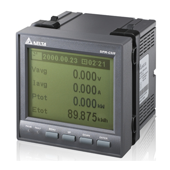
Delta Electronics website (http://www.delta.com.tw/ia/). Overview The DPM-C530 is equipped with a large, back-lit LCD display that displays up to four lines of information. 1 - 2... -
Page 9: Safety Precautions
C ha pt er 1 P r o d u c t I n t r o d u c t i o n Safety Precautions Installation Notes Install the power meter according to instructions on the manual. Use appropriate personal protective equipment (PPE) and follow safe electrical work practices. - Page 10 D P M - C 5 3 0 O p e r a t i o n M a n u a l MEMO 1 - 4...
-
Page 11: Chapter 2 Product Specifications
Chapter 2 Product Specifications Table of Contents Electrical Characteristics ..............2-2 Communications Specifications ............2-4 Operating the Display ................2-4 2.3.1 Menu Tree ..................2-5 Dimensions ..................2-6 2 - 1... -
Page 12: Electrical Characteristics
D P M - C 5 3 0 O p e r a t i o n M a n u a l Electrical Characteristics Measurement Accuracy Voltage, current ± 0.5% Real power ± 0.5% Electric Electric quantities Real power, reactive ±... - Page 13 C h a p t e r 2 P r o d u c t Sp e c i f i c a t i o n s Dimension (W x H x D) 96 x 96 x 95.4 mm Mechanical Characteristics IP Degree of Protection...
-
Page 14: Communications Specifications
D P M - C 5 3 0 O p e r a t i o n M a n u a l Communications Specifications Communications RS-485 Modbus-RTU, Modbus ASCII, BACnet MS/TP Baud rate 9600 / 19200 / 38400 bps Operating the Display Title Display area... -
Page 15: Menu Tree
C h a p t e r 2 P r o d u c t Sp e c i f i c a t i o n s 2.3.1 Menu Tree Display Menu Tree 1. Time, Date 2. Mete r Info 3. -
Page 16: Dimensions
D P M - C 5 3 0 O p e r a t i o n M a n u a l Dimensions Front Unit: mm Back: Unit: mm 2 - 6... -
Page 17: Chapter 3 Installation
Chapter 3 Installation Table of Contents Installation ..................3-2 3.1.1 Installation Environment ..............3-2 3.1.2 Installation Notes ................3-2 Basic Checks ..................3-4 Wiring ....................3-4 3.3.1 Wiring Diagrams ................3-4 3.3.2 Communication Characteristics ............3-6 3 - 1... -
Page 18: Installation
D P M - C 5 3 0 O p e r a t i o n M a n u a l 3.1 Installation 3.1.1 Installation Environment Keep the product in the shipping carton before installation. Store the product properly when it is not to be used for an extended period of time to retain the warranty coverage. - Page 19 C h a p t e r 3 I n s ta l l a t i o n Step 3: Allow 50 mm (2 inches) of clearance at the back of the meter for heat dissipation. Mounting Hole Dimensions Unit: mm 3 - 3...
-
Page 20: Basic Checks
D P M - C 5 3 0 O p e r a t i o n M a n u a l 3.2 Basic Checks Items Contents Regularly check for mounting looseness where the power meter and device are connected. - Page 21 C h a p t e r 3 I n s ta l l a t i o n Connection Diagrams 3PH3W, Δ connection, 3 CT, No PT 3PH3W, Δ connection, 2 CT, No PT 3PH3W, Δ connection, 3 CT, 2 PT 3PH4W, Y connection, 3 CT, No PT 3PH4W, Y connection, 3 CT, 3 PT 3PH4W, Y connection, 2 CT, 3 PT...
-
Page 22: Communication Characteristics
D P M - C 5 3 0 O p e r a t i o n M a n u a l The following table lists the symbols used in the diagram. Symbol Current Terminal Voltage Description Grounding Fuse transformer block transformer... -
Page 23: Chapter 4 Operation
Chapter 4 Operation Table of Contents General Operation ................4-2 4.1.1 Setting Menu ................. 4-2 Basic Setups ..................4-3 4.2.1 Set up the Time and Date ............... 4-3 4.2.2 Meter Information ................4-3 4.2.3 Set up the Communication .............. 4-3 4.2.4 Set up the Transformer Ratio ............ -
Page 24: General Operation
DP M- C5 3 0 O p er at i on Ma n ua l 4.1 General Operation Use the UP and DOWN keys to switch among setting pages. Use the MENU key to go back to Menu page. Note 1: Use the ENTER key to enter a setting page and confirm the setting. 4.1.1 Setting Menu ... -
Page 25: Basic Setups
MENU to cancel without saving the changes. Press MENU to go back to the setting menu. 4.2.2 Meter Information Meter related information: Model: DPM-C530 FW Version: Firmware version; 1.xxxx FW Date: Firmware release date; XXXXYYZZ (XXXX: year, YY: month, ZZ: day) ... -
Page 26: Set Up The Transformer Ratio
DP M- C5 3 0 O p er at i on Ma n ua l Set up Steps Press MENU to display the setting menu. Select 0 and press ENTER to enter the Setup menu. Select 3 and press ENTER to enter the Communication menu. Select Address and then press ENTER to set communication parameters. -
Page 27: Set Up The System
C h a p t e r 4 O p e r a t i o n 4.2.5 Set up the System Language: Language displayed on the power meter LCD; options are English (default), Japanese, Simplified Chinese and Traditional Chinese. ... -
Page 28: Set Up The Alarms
DP M- C5 3 0 O p er at i on Ma n ua l 4.2.6 Set up the Alarms There are 29 types of supported alarm, including Over Current, Under Current, Over Neutral Current, Over Voltage LL, Under Voltage LL, Over Voltage LN, Under Voltage LN, Over Volt Unbalance, Over AMP Unbalance, Over Active power, Over Reactive Power, Over Apparent Power, LEAD PF, Lag PF, Lead DPF, Lag DPF, Over Current Demand, Over kW Demand, Over kVAR Demand, Over kVA Demand, Over Frequency, Under Frequency, Over Voltage THD, Over Current THD, Phase Loss, Meter Reset, Phase Rotation, Over DUI and... -
Page 29: Set Up The Demands
C h a p t e r 4 O p e r a t i o n 19. Select Time Delay and then press ENTER to set the alarm delay time (cancel). 20. After you select the option, use UP and DOWN to select the value. 21. -
Page 30: Set Up The Resets
DP M- C5 3 0 O p er at i on Ma n ua l 4.2.8 Set up the Resets There are seven types of supported resets, including Default, Energy, Demand, Alarm, MaxMin, Data Log, and ClearAll. Default: Restore all the settings back to the defaults. ... -
Page 31: Set Up The Data Log
C h a p t e r 4 O p e r a t i o n the setting. Repeat steps 3–4 until you complete the settings. Press ENTER to save the setting or press MENU to cancel without saving the changes. Press MENU to go back to the setting menu. -
Page 32: Set Up The Auto Maxmin
DP M- C5 3 0 O p er at i on Ma n ua l Interval 1 minute to 4 minutes 5 minutes to 5 to 59 seconds Item and 59 seconds 60 minutes Maximum Number of Parameters Maximum Recording days 4.3.3 Set up the Auto Max/Min ... -
Page 33: Power Analysis Values
C h a p t e r 4 O p e r a t i o n Block transmission: Mirror the address of the to-be-read measured values to sequential Modbus addresses. The mirrored addresses are 0x100–0x1E7. The default is 0xFFFF. ... -
Page 34: Demand Calculation Method
DP M- C5 3 0 O p er at i on Ma n ua l 4.4.2 Demand Calculation Method The power meter provides measured values for current demand, active power demand, reactive power demand and apparent power demand. You can also calculate the last, present, predicted and peak demand values from above measured values. -
Page 35: Overview Of Parameters
Chapter 5 Parameters and Functions Table of Contents Overview of Parameters ..............5-2 5 - 1... - Page 36 D PM –C53 0 O pera ti on M an ua l 5.1 Overview of Parameters Modbus Data Read (R) / Address Data Item Range Unit Size Type Write (W) Modicom (byte) Format 0. System Parameters: 0001 – 00FF Year: 00–99 Year, 40002 byte...
- Page 37 Ch ap te r 5 Para me ters a nd Func tio ns 40013 Reserved 0: 3φ4W 1: 3φ3W Power system 40014 word configuration 2: 1φ2W 3: 1φ3W 40015 Primary CT (A) 1 – 9999 uint 0: 1A 40016 Secondary CT (A) word 1: 5A 40017...
- Page 38 D PM –C53 0 O pera ti on M an ua l 0: 100% 40022 Backlight word 1: 50% 2: 25% 0: 9600 40023 Baud Rate 1: 19200 word 2: 38400 0: ASCII 40024 Communication mode 1: RTU word 2: BACnet MSTP 0: 8 40025 Data bit...
- Page 39 Ch ap te r 5 Para me ters a nd Func tio ns 8: Reset time of use value and accumulated energy value from auto recording 9: Reset accumulated energy value from energy saving mode of the measured equipment 40030 Demand 0: block word...
- Page 40 D PM –C53 0 O pera ti on M an ua l Pickup time delay 0 – 99 word 40042 (alarm–trigger delay) Dropout setpoint 40043 (current value 0.000 – 99999.999 float exceeding this value 40044 clears alarm) Dropout time delay 0 –...
- Page 41 Ch ap te r 5 Para me ters a nd Func tio ns Pickup time delay 40056 0 – 99 word (alarm–trigger delay) Dropout setpoint (line 40057 voltage value below 0.000 – 99999.999 float this value clears 40058 alarm) Dropout time delay 40059 0 –...
- Page 42 D PM –C53 0 O pera ti on M an ua l Pickup time delay 40070 0 – 99 word (alarm–trigger delay) Dropout setpoint 40071 (phase voltage value 0.000 – 99999.999 float below this value 40072 clears alarm) Dropout time delay 40073 0 –...
- Page 43 Ch ap te r 5 Para me ters a nd Func tio ns Pickup time delay word 40084 0 – 99 (alarm–trigger delay) Dropout setpoint (over 40085 voltage unbalance float 0.00 – 99.99 value below this value 40086 clears alarm) Dropout time delay word 40087...
- Page 44 D PM –C53 0 O pera ti on M an ua l Pickup time delay 40098 word 0 – 99 (alarm–trigger delay) Dropout setpoint (total 40099 active power value 0.000 – 99999.999 float below this value 40100 clears alarm) Dropout time delay 40101 word 0 –...
- Page 45 Ch ap te r 5 Para me ters a nd Func tio ns Pickup time delay 40112 word 0 – 99 (alarm–trigger delay) Dropout setpoint (total 40113 apparent power value 0.000 – 99999.999 float below this value 40114 clears alarm) Dropout time delay 40115 word...
- Page 46 D PM –C53 0 O pera ti on M an ua l Pickup time delay word 40126 0 – 99 (alarm–trigger delay) Dropout setpoint 40127 (total power factor 0.00000 – 1.00000 float value exceeding this 40128 value clears alarm) Dropout time delay word 40129 0 –...
- Page 47 Ch ap te r 5 Para me ters a nd Func tio ns factor value below this 40139 value triggers alarm) Pickup time delay word 40140 0 – 99 (alarm–trigger delay) Dropout setpoint (total 40141 displacement power factor value 0.00000 – 1.00000 float exceeding this value 40142...
- Page 48 D PM –C53 0 O pera ti on M an ua l Pickup setpoint 40152 (active power demand 0.000 – 99999.999 float value exceeding this 40153 value triggers alarm) Pickup time delay word 40154 0 – 99 (alarm–trigger delay) Dropout setpoint 40155 (active power demand 0.000 –...
- Page 49 Ch ap te r 5 Para me ters a nd Func tio ns Alarm – Over Apparent Power Demand 0: Disable Alarm enable word 40165 1: Enable Pickup setpoint 40166 (apparent power demand value 0.000 – 99999.999 float exceeding this value 40167 triggers alarm) Pickup time delay...
- Page 50 D PM –C53 0 O pera ti on M an ua l (frequency value 40177 below this value clears alarm) Dropout time delay 40178 word 0 – 99 (alarm–clear delay) Alarm – Under Frequency 0: Disable 40179 Alarm enable word 1: Enable Pickup setpoint 40180...
- Page 51 Ch ap te r 5 Para me ters a nd Func tio ns Dropout setpoint 40190 (THD voltage value 0.000 – 999.999 float below this value, 40191 alarm cleared) Dropout time delay word 40192 0 – 99 (alarm–clear delay) Alarm – Over THD Current 0: Disable Alarm enable word...
- Page 52 D PM –C53 0 O pera ti on M an ua l Pickup time delay word 40210 0 – 99 (alarm–trigger delay) Dropout setpoint (DUI 40211 value below this 0.000 – 99999.999 float kW / m value, alarm cleared) 40212 Dropout time delay word 40213...
- Page 53 Ch ap te r 5 Para me ters a nd Func tio ns 1. Meter Parameters: 0100 – 01FF 40257 Phase A voltage 0.000 – 99999.999 float 40258 40259 Phase B voltage 0.000 – 99999.999 float 40260 40261 Phase C voltage 0.000 –...
- Page 54 D PM –C53 0 O pera ti on M an ua l 40280 unbalance 40281 A–B line voltage 0.00 – 99.99 float unbalance 40282 40283 B–C line voltage 0.00 – 99.99 float unbalance 40284 40285 C–A line voltage 0.00 – 99.99 float unbalance 40286...
- Page 55 Ch ap te r 5 Para me ters a nd Func tio ns 40304 unbalance 40305 Current unbalance 0.00 – 99.99 float 40306 40307 0.00000 – 1.00000 Total power factor float (positive: lag; negative: lead) 40308 40309 Power factor of phase 0.00000 –...
- Page 56 D PM –C53 0 O pera ti on M an ua l 40328 power of phase A 40329 Instantaneous active 0.000 – 99999.999 float power of phase B 40330 40331 Instantaneous active 0.000 – 99999.999 float power of phase C 40332 40333 Total instantaneous...
- Page 57 Ch ap te r 5 Para me ters a nd Func tio ns 40351 Active energy of three 0.000 – 99999,999,999.999 float - phase received 40352 40353 Reactive energy of three - phase 0.000 – 99999,999,999.999 float kVARh 40354 delivered 40355 Reactive energy of three - phase...
- Page 58 D PM –C53 0 O pera ti on M an ua l Apparent energy of 40369 three - phase delivered + apparent 0.000 – 99999,999,999.999 float kVAh energy of three - 40370 phase received Apparent energy of 40371 three - phase delivered –...
- Page 59 Ch ap te r 5 Para me ters a nd Func tio ns distortion for phase 40388 A–B voltage 40389 Total harmonic distortion for phase 0.000 – 999.999 float 40390 B–C voltage Total harmonic 40391 distortion for phase 0.000 – 999.999 float 40392 C–A voltage...
- Page 60 D PM –C53 0 O pera ti on M an ua l 40408 demand value Second: 00–59 word Second 40409 Present three - phase 0.000 – 99999.999 float active power demand 40410 40411 Last three - phase 0.000 – 99999.999 float active power demand 40412...
- Page 61 Ch ap te r 5 Para me ters a nd Func tio ns 40427 Peak value of three - phase reactive power 0.000 – 99999.999 float kVAR 40428 demand Year: 00–99 Year, Date of the three - 40429 byte Month phase reactive power Month: 1–12 demand...
- Page 62 D PM –C53 0 O pera ti on M an ua l 40446 40447 EUI (kWh / Floor kWh/ 0.000 – 99999,999,999.999 float Area) 40448 40449 Auto Date 1 – positive 0.000 – 99999,999,999.999 float active energy 40450 40451 Auto Date 1 – reversed active 0.000 –...
- Page 63 Ch ap te r 5 Para me ters a nd Func tio ns 40469 Instantaneous 0.000 – 99999.999 float fundamental active 40470 power of phase B 40471 Instantaneous 0.000 – 99999.999 float fundamental active 40472 power of phase C 40473 Instantaneous total 0.000 –...
- Page 64 D PM –C53 0 O pera ti on M an ua l Year: 00–99 Year, 40515 byte Date of maximum Month Month: 1–12 A–B line voltage 40516 Date: 1–31 word Date Hour: 00–23 Hour, 40517 byte Time of maximum Minute Minute: 00–59 A–B line voltage 40518...
- Page 65 Ch ap te r 5 Para me ters a nd Func tio ns Year: 00–99 Year, 40533 byte Date of maximum Month Month: 1–12 phase A voltage 40534 Date: 1–31 word Date Hour: 00–23 Hour, 40535 byte Time of maximum Minute Minute: 00–59 phase A voltage...
- Page 66 D PM –C53 0 O pera ti on M an ua l Year: 00–99 Year, 40551 byte Date of maximum Month Month: 1–12 phase A current 40552 Date: 1–31 word Date Hour: 00–23 Hour, 40553 byte Time of maximum Minute Minute: 00–59 phase A current 40554...
- Page 67 Ch ap te r 5 Para me ters a nd Func tio ns Year: 00–99 Year, 40569 byte Date of maximum Month Month: 1–12 neutral line current 40570 Date: 1–31 word Date Hour: 00–23 Hour, 40571 byte Time of maximum Minute Minute: 00–59 neutral line current...
- Page 68 D PM –C53 0 O pera ti on M an ua l Year: 00–99 Year, 40587 byte Date of maximum Month Month: 1–12 total active power 40588 Date: 1–31 word Date Hour: 00–23 Hour, 40589 byte Time of maximum Minute Minute: 00–59 total active power 40590...
- Page 69 Ch ap te r 5 Para me ters a nd Func tio ns Year: 00–99 Date of maximum Year, 40605 byte total harmonic Month Month: 1–12 distortion for A–B 40606 line voltage Date: 1–31 word Date Hour: 00–23 Time of maximum Hour, 40607 byte...
- Page 70 D PM –C53 0 O pera ti on M an ua l Year: 00–99 Date of maximum Year, 40623 byte total harmonic Month Month: 1–12 distortion for phase 40624 A voltage Date: 1–31 word Date Hour: 00–23 Time of maximum Hour, 40625 byte...
- Page 71 Ch ap te r 5 Para me ters a nd Func tio ns Year: 00–99 Date of maximum Year, 40641 byte total harmonic Month Month: 1–12 distortion for line 40642 voltage Date: 1–31 word Date Hour: 00–23 Time of maximum Hour, 40643 byte...
- Page 72 D PM –C53 0 O pera ti on M an ua l Year: 00–99 Date of maximum Year, 40659 byte total harmonic Month Month: 1–12 distortion for phase 40660 B current Date: 1–31 word Date Hour: 00–23 Time of maximum Hour, 40661 byte...
- Page 73 Ch ap te r 5 Para me ters a nd Func tio ns harmonic distortion for 40676 A–B line voltage unbalance Date of maximum Year: 00–99 Year, 40677 byte total harmonic Month Month: 1–12 distortion for A–B line voltage 40678 Date: 1–31 word Date...
- Page 74 D PM –C53 0 O pera ti on M an ua l line voltage 40690 Date: 1–31 word Date unbalance Time of maximum Hour: 00–23 Hour, 40691 byte total harmonic Minute Minute: 00–59 distortion for C–A line voltage 40692 Second: 00–59 word Second unbalance Maximum total...
- Page 75 Ch ap te r 5 Para me ters a nd Func tio ns harmonic distortion for 40706 phase C voltage unbalance Date of maximum Year: 00–99 Year, 40707 byte total harmonic Month Month: 1–12 distortion for phase C voltage unbalance 40708 Date: 1–31 word...
- Page 76 D PM –C53 0 O pera ti on M an ua l Hour: 00–23 Time of maximum Hour, 40721 byte total harmonic Minute Minute: 00–59 distortion for phase 40722 voltage unbalance Second: 00–59 word Second Maximum total 40723 harmonic distortion for 0.00 –...
- Page 77 Ch ap te r 5 Para me ters a nd Func tio ns Year: 00–99 Date of maximum Year, 40737 byte total harmonic Month Month: 1–12 distortion for phase 40738 C current unbalance Date: 1–31 word Date Hour: 00–23 Time of maximum Hour, 40739 byte...
- Page 78 D PM –C53 0 O pera ti on M an ua l 40776 voltage Year: 00–99 Year, 40777 byte Date of minimum B–C Month Month: 1–12 line voltage 40778 Date: 1–31 word Date Hour: 00–23 Hour, 40779 byte Time of minimum B–C Minute Minute: 00–59 line voltage...
- Page 79 Ch ap te r 5 Para me ters a nd Func tio ns Year: 00–99 Year, 40795 byte Date of minimum Month Month: 1–12 phase B voltage 40796 Date: 1–31 word Date Hour: 00–23 Hour, 40797 byte Time of minimum Minute Minute: 00–59 phase B voltage...
- Page 80 D PM –C53 0 O pera ti on M an ua l Year: 00–99 Year, 40813 byte Date of minimum Month Month: 1–12 phase B current 40814 Date: 1–31 word Date Hour: 00–23 Hour, 40815 byte Time of minimum Minute Minute: 00–59 phase B current 40816...
- Page 81 Ch ap te r 5 Para me ters a nd Func tio ns Year: 00–99 Year, 40831 byte Date of minimum Month Month: 1–12 frequency value 40832 Date: 1–31 word Date Hour: 00–23 Hour, 40833 byte Time of minimum Minute Minute: 00–59 frequency value 40834...
- Page 82 D PM –C53 0 O pera ti on M an ua l Year: 00–99 Year, 40849 byte Date of minimum total Month Month: 1–12 reactive power 40850 Date: 1–31 word Date Hour: 00–23 Hour, 40851 byte Time of minimum total Minute Minute: 00–59 reactive power...
- Page 83 Ch ap te r 5 Para me ters a nd Func tio ns Year: 00–99 Year, Date of minimum total byte 40867 Month Month: 1–12 harmonic distortion for B–C line voltage Date: 1–31 word Date 40868 Hour: 00–23 Hour, Time of minimum total byte 40869 Minute...
- Page 84 D PM –C53 0 O pera ti on M an ua l Year: 00–99 Year, Date of minimum total byte 40885 Month Month: 1–12 harmonic distortion for phase B voltage Date: 1–31 word Date 40886 Hour: 00–23 Hour, Time of minimum total byte 40887 Minute...
- Page 85 Ch ap te r 5 Para me ters a nd Func tio ns Year: 00–99 Year, Date of minimum total byte 40903 Month Month: 1–12 harmonic distortion for phase voltage Date: 1–31 word Date 40904 Hour: 00–23 Hour, Time of minimum total byte 40905 Minute...
- Page 86 D PM –C53 0 O pera ti on M an ua l Year: 00–99 Year, Date of minimum total byte 40921 Month Month: 1–12 harmonic distortion for phase C current Date: 1–31 word Date 40922 Hour: 00–23 Hour, Time of minimum total byte 40923 Minute...
- Page 87 Ch ap te r 5 Para me ters a nd Func tio ns harmonic distortion for B–C line voltage 40938 unbalance Date of minimum total Year: 00–99 Year, byte 40939 harmonic distortion for Month Month: 1–12 B–C line voltage unbalance Date: 1–31 word Date...
- Page 88 D PM –C53 0 O pera ti on M an ua l Hour: 00–23 Time of minimum total Hour, byte 40953 harmonic distortion for Minute Minute: 00–59 phase A voltage unbalance Second: 00–59 word Second 40954 Minimum total 40955 harmonic distortion for 0.00 –...
- Page 89 Ch ap te r 5 Para me ters a nd Func tio ns Year: 00–99 Date of minimum total Year, byte 40969 harmonic distortion for Month Month: 1–12 line voltage unbalance Date: 1–31 word Date 40970 Time of minimum total Hour: 00–23 Hour, byte...
- Page 90 D PM –C53 0 O pera ti on M an ua l harmonic distortion for phase B current 40986 unbalance Date of minimum total Year: 00–99 Year, byte 40987 harmonic distortion for Month Month: 1–12 phase B current unbalance Date: 1–31 word Date 40988...
- Page 91 Ch ap te r 5 Para me ters a nd Func tio ns Hour: 00–23 Time of minimum total Hour, byte 41001 harmonic distortion for Minute Minute: 00–59 phase current unbalance Second: 00–59 word Second 41002 4. Alarm:0400 – 04FF 0: Cleared Alarm status of over 41025...
- Page 92 D PM –C53 0 O pera ti on M an ua l 0: Cleared Alarm status of over 41037 word neutral current 1: Triggered Alarm times of over 41038 1–255 word Times neutral current Year: 00–99 Year, 41039 byte Alarm date of over Month Month: 1–12 neutral current...
- Page 93 Ch ap te r 5 Para me ters a nd Func tio ns 41052 Date: 1–31 word Date Hour: 00–23 Hour, 41053 byte Alarm time of under Minute Minute: 00–59 line voltage 41054 Second: 00–59 word Second 0: Cleared Alarm status of over 41055 word phase voltage...
- Page 94 D PM –C53 0 O pera ti on M an ua l 0: Cleared Alarm status of over 41067 word voltage unbalance 1: Triggered Alarm times of over 41068 1–255 word Times voltage unbalance Year: 00–99 Year, 41069 byte Alarm date of over Month Month: 1–12 voltage unbalance...
- Page 95 Ch ap te r 5 Para me ters a nd Func tio ns 41082 Date: 1–31 word Date Hour: 00–23 Hour, 41083 byte Alarm time of over Minute Minute: 00–59 active energy 41084 Second: 00–59 word Second 0: Cleared Alarm status of over 41085 word reactive energy...
- Page 96 D PM –C53 0 O pera ti on M an ua l 0: Cleared Alarm status of power 41097 word factor (lead) 1: Triggered Alarm times of power 41098 1–255 word Times factor (lead) Year: 00–99 Year, 41099 byte Alarm date of power Month Month: 1–12 factor (lead)
- Page 97 Ch ap te r 5 Para me ters a nd Func tio ns Year: 00–99 Year, Alarm date of 41111 byte Month Month: 1–12 displacement power factor (lead) 41112 Date: 1–31 word Date Hour: 00–23 Hour, Alarm time of 41113 byte Minute Minute: 00–59...
- Page 98 D PM –C53 0 O pera ti on M an ua l Hour: 00–23 Hour, 41125 byte Alarm time of over Minute Minute: 00–59 current demand 41126 Second: 00–59 word Second 0: Cleared Alarm status of over 41127 word active power demand 1: Triggered Alarm times of over 41128...
- Page 99 Ch ap te r 5 Para me ters a nd Func tio ns Alarm status of over 0: Cleared 41139 apparent power word 1: Triggered demand Alarm times of over 41140 apparent power 1–255 word Times demand Year: 00–99 Year, Alarm date of over 41141 byte...
- Page 100 D PM –C53 0 O pera ti on M an ua l Year: 00–99 Year, 41153 byte Alarm date of under Month Month: 1–12 frequency 41154 Date: 1–31 word Date Hour: 00–23 Hour, 41155 byte Alarm time of under Minute Minute: 00–59 frequency 41156...
- Page 101 Ch ap te r 5 Para me ters a nd Func tio ns Hour: 00–23 Hour, Alarm time of total 41167 byte Minute Minute: 00–59 harmonic distortion for over current 41168 Second: 00–59 word Second 0: Cleared Alarm status of phase 41169 word loss...
- Page 102 D PM –C53 0 O pera ti on M an ua l Alarm times of phase 41182 1–255 word Times rotation Year: 00–99 Year, 41183 byte Alarm date of phase Month Month: 1–12 rotation 41184 Date: 1–31 word Date Hour: 00–23 Hour, 41185 byte...
- Page 103 Ch ap te r 5 Para me ters a nd Func tio ns Hour: 00–23 Hour, 41197 byte Alarm time of over Minute Minute: 00–59 41198 Second: 00–59 word Second 5. Advanced Settings: 0500 – 05FF 41281 Floor Area 1–65536 word Minute: 00–60 Minute,...
- Page 104 D PM –C53 0 O pera ti on M an ua l 41362 Setting group 70 0x100 – 0x1E7 word Year: 00–99 Year, 41363 Reset energy date byte Month Month: 1–12 41364 Reset energy date Date: 1–31 word Date Hour: 00–23 Hour, 41365 Reset energy time...
- Page 105 Ch ap te r 5 Para me ters a nd Func tio ns Parameter #6 for data 8: Total reactive power 41377 9: Total apparent power Parameter #7 for data 41378 10: Positive active energy Parameter #8 for data 41379 11: Reversed active energy 12: Positive reactive energy Parameter #9 for data...
- Page 106 D PM –C53 0 O pera ti on M an ua l Hour: 00–23 Time of Use #1 stop Hour, 41393 byte time Minute Minute: 00–59 0: Sharp (P1) 1: Peak (P2) 41394 Time of Use #2 word 2: Shoulder (P3) 3: Off–peak (P4) Hour: 00–23 Time of Use #2 start...
- Page 107 Ch ap te r 5 Para me ters a nd Func tio ns Hour: 00–23 Time of Use #4 stop Hour, 41402 byte time Minute Minute: 00–59 0: Sharp (P1) 1: Peak (P2) 41403 Time of Use #5 word 2: Shoulder (P3) 3: Off–peak (P4) Hour: 00–23 Time of Use #5 start...
- Page 108 D PM –C53 0 O pera ti on M an ua l Hour: 00–23 Time of Use #7 stop Hour, 41411 byte time Minute Minute: 00–59 0: Sharp (P1) 1: Peak (P2) 41412 Time of Use #8 word 2: Shoulder (P3) 3: Off–peak (P4) Hour: 00–23 Time of Use #8 start...
- Page 109 Ch ap te r 5 Para me ters a nd Func tio ns 41615 P3 (active energy of the shoulder period) 41616 41619 P4 (active energy of the off–peak period) 41620 41623 0 o’clock positive active energy 41624 41625 0 o’clock reversed active energy 41626 41627...
- Page 110 D PM –C53 0 O pera ti on M an ua l Day: 0–65535 word 41724 Total time used in Hour: 00–23 Hour, non–energy saving byte 41725 Minute Minute: 00–59 mode Second: 00–59 word Second 41726 41727 Accumulated positive energy in non–energy 0.000 –...
- Page 111 Ch ap te r 5 Para me ters a nd Func tio ns The 31 harmonic for phase B voltage The 1 harmonic for phase C voltage 0706 The 11 harmonic for phase C voltage 0707 0.000 – 999.999 float The 21 harmonic for phase C voltage...
- Page 112 D PM –C53 0 O pera ti on M an ua l The 21 harmonic for phase B current 070E The 31 harmonic for phase B current The 1st harmonic for phase C current 070F The 11 harmonic for phase C current 0710 0.000 –...
- Page 113 Ch ap te r 5 Para me ters a nd Func tio ns Displacement power factor float Total active power float Total reactive power float Total apparent power float 10. Positive active energy float 11. Reversed active energy float 12. Positive reactive energy float 13.
- Page 114 D PM –C53 0 O pera ti on M an ua l Over Voltage LL byte Under Voltage LL byte Over Voltage LN byte Under Voltage LN byte Over Volt Unbalance byte Over AMP Unbalance byte 10. Over Active power byte 11.
- Page 115 Ch ap te r 5 Para me ters a nd Func tio ns 25. Phase Loss byte 26. Meter Reset byte 27. Phase Rotation byte 28. Over DUI byte 29. Over EUI byte 1 – 29 B700 Alarm History 1 byte (high byte, types) (low byte, times)
- Page 116 D PM –C53 0 O pera ti on M an ua l Second: 00–59 B8FB word Second Year: 00–99 Year, B8FC Alarm 03 Date byte Month Month: 1–12 Date: 1–31 B8FD word Date Hour: 00–23 Hour, B8FE Alarm 03 Time byte Minute Minute: 00–59...
-
Page 117: Error Codes
Chapter 6 Error Codes Table of Contents Error Codes ..................6-2 Alarm Types ..................6-2 6 - 1... - Page 118 D P M - C 5 3 0 O p e r a t i o n M a n u a l 6.1 Error Codes When an error occurs during operation, the power monitor sends an error code through Modbus. The following table lists the error codes and causes.
- Page 119 C h a p t e r 6 E r r o r C o d e s Number Alarm Type Description Lag DPF The lagging power factor demand is below the setting value. Over Current Demand The current demand exceeds the setting value. Over kW Demand The total active power factor demand exceeds the setting value.
- Page 120 D P M - C 5 3 0 O p e r a t i o n M a n u a l Memo 6 - 4...
-
Page 121: A.1 Dct1000 Series
12 A Appendix A Accessories Table of Contents DCT1000 Series ...................A-2 DCT2000 Series ...................A-4 A - 1... - Page 122 D P M - C 5 3 0 O p e r a t i o n M a n u a l When measured current is higher than the rated specification for the device, use of an external current transformer (CT) is necessary.
- Page 123 A pp e nd ix A Ac c es s o r i es Model Dimension (mm) Number External Dimension: DCT-S301C 90 x 40 x 111 DCT-S211C Size of Opening: 21 x 32 DCT-S221C DCT-S231C External Dimension: DCT-S241C 116.5 x 52 x 147 DCT-S251C Size of Opening: 50 x 80 DCT-S261C...
-
Page 124: A.2 Dct2000 Series
D P M - C 5 3 0 O p e r a t i o n M a n u a l External Dimension: DCT-S291C 186.5 x 52 x 252 Size of Opening: 81 x 160.5 DCT-S2A1C DCT-S2B1C A.2 DCT2000 Series Electromagnetic Compatibility: UL, UL2808. - Page 125 A pp e nd ix A Ac c es s o r i es Model Dimension (mm) Number External Dimension: DCT-S201B 90 x 40 x 110 Size of Opening: 20 x 30 DCT-S211B DCT-S221B External Dimension: DCT-S231B 115 x 57 x 158 DCT-S241B Size of Opening: 50 x 80...
- Page 126 D P M - C 5 3 0 O p e r a t i o n M a n u a l MEMO A - 6...