Table of Contents
Advertisement
Quick Links
Advertisement
Table of Contents

Related Manuals for Delta DPM-C520


Summary of Contents for Delta DPM-C520
- Page 2 Mail: Sales.lA.RU@deltaww.com Raleigh Office TEL: + 7 495 644 3240 P.O. Box 12173 5101 Davis Drive Research Triangle Park, NC 27709, U.S.A. Turkey: Delta Greentech Elektronik San. Ltd. Sti. (Turkey) TEL: 1-919-767-3813 FAX: 1-919-767-3969 $erifali Mah. Hendem Cad. Kul Sok. No:16-A 自...
- Page 3 DPM-C520/C520W Operation Manual Revision History Ve r s i o n R e v i s i o n D a t e 2 0 1 9 / 0 5 / 1 5 T h e f i r s t v e r s i o n w a s p u b l i s h e d .
-
Page 4: Table Of Contents
DPM-C520/C520W Operation Manual Table of Contents Chapter 1 Product Introduction Preface ....................1-2 Overview ................... 1-3 Safety Precautions ................1-4 Chapter 2 Product Specifications Electrical Characteristics ..............2-2 Communications Specifications ............2-3 Operating the Display ................ 2-4 2.3.1 Menu Tree ..................2-5 Dimensions .................. - Page 5 4.2.6 Current Transformer Setup (CT) ............4-5 4.2.7 Potential Transformer Setup (PT) ............ 4-6 4.2.8 Reset Setup (RST) ................ 4-6 4.2.9 Meter Information (INF) ..............4-7 4.2.10 Wi-Fi Setup (485 ON/OFF) only available for DPM-C520W ....4-7 4.2.11 Alarm Setup ................. 4-7 4.2.12 Parameter Grouping Setup .............
-
Page 6: Chapter1 Product Introduction
Chapter1 Product Introduction Table of Contents Preface ....................1-2 Overview ..................... 1-3 Safety Precautions ................1-4 1 - 1... -
Page 7: Preface
If you still experience issues when using the device, please contact your distributor or our customer service center. As the product is updated and improved, changes to the specifications will be included in the newest version of the manual which you can get by contacting your distributor or downloading it from the Delta Electronics website (http://www.delta.com.tw/ia/). -
Page 8: Overview
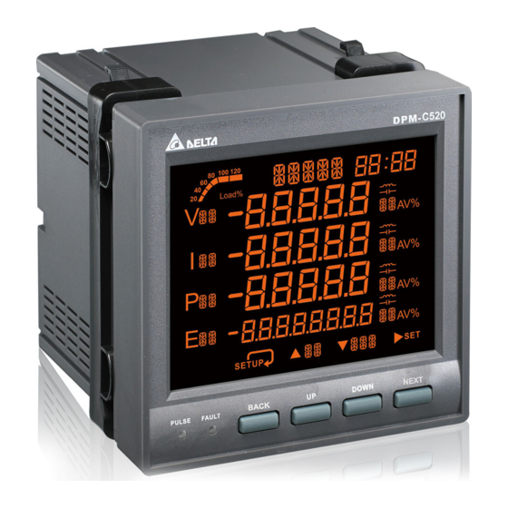
Ch a pt er 1 Pr o duc t In tr o d uc t i on Overview DPM-C520 DPM-C520W 1 - 3... -
Page 9: Safety Precautions
DP M- C5 2 0/ C 52 0W O per a t io n M a nu a l Safety Precautions Installation Notes Install the power meter according to instructions on the manual. Use appropriate personal protective equipment (PPE) and follow safe electrical work practices. ... - Page 10 Ch a pt er 1 Pr o duc t In tr o d uc t i on Wiring Notes When the measured current is higher than the rated specification for the device, consider using an external current transformer (CT). When the measured voltage is higher than the rated specification for the device, ...
- Page 11 DP M- C5 2 0/ C 52 0W O per a t io n M a nu a l MEMO 1 - 6...
- Page 12 Chapter2 Specifications Table of Contents Electrical characteristics ..............2-2 Communications Specifications ............2-3 Operating the Display ................2-4 2.3.1 Menu Tree ..................2-5 Dimensions ..................2-6 2 - 1...
-
Page 13: Electrical Characteristics
D PM -C52 0 /C5 20W O pe ra tion Man ua l Electrical characteristics Measurement Accuracy Voltage, current ± 0.5% Real power ± 0.5% Electric Electric quantities Real power, reactive ± 0.5% Reactive energy ± 0.5% power, apparent power power Total Harmonic Power factor... -
Page 14: Communications Specifications
Conducted Emissions FCC Part 15 Class A, EN55011 Class A Harmonics Emissions IEC 61000-3-2 Flicker Emissions IEC 61000-3-3 Communications Specifications Communications DPM-C520 DPM-C520W RS-485 Modbus-RTU Modbus-RTU Baud rate 9600 / 19200 / 38400 bps 9600 / 19200 / 38400 bps... -
Page 15: Operating The Display
Go to setting mode and go to the next setting NEXT Key * For DPM-C520W: FW V1.0008 or earlier versions and DPM-C520: FW V1.0004 or earlier versions: The UP key is used for decrementing the number in the setting mode. -
Page 16: Menu Tree
Ch ap te r 2 Spec i fica ti ons 2.3.1 Menu Tree SETUP TIM DAT COM SYS CT PT RST INFO VLN VLL ULN ULL AMP UNB PF DPF PQS P Q S +Ph -Ph +Qh -Qh +Sh -Sh TOT AMP VLN VLL VLN VLL I PF PWR Hz VLN VLL I PF PWR Hz... -
Page 17: Dimensions
Negative Reactive Energy Active power Positive Apparent Power Power Factor Negative Apparent Power Active Power, Reactive 485 ON Disable Wi-Fi Function Power, Apparent Power Parity 485 OFF Enable Wi-Fi Function Potential Transformer Dimensions DPM-C520 (Front) Unit: mm 2 - 6... - Page 18 Ch ap te r 2 Spec i fica ti ons DPM-C520W (Front) DPM-C520 / C520W (Back) 2 - 7...
- Page 19 D PM -C52 0 /C5 20W O pe ra tion Man ua l Function VOLTAGE CURRENT 20V L-N ~ 400V L-N Rated voltage 35V L-L ~ 690V L-L L1/+ 80 ~ 265 VAC Control power 400 mA MAX 100 ~ 300 VDC L2/- Rated current 1A ~ 5A...
-
Page 20: Chapter 3 Installation
Chapter 3 Installation Table of Contents Installation ..................3-2 3.1.1 Installation Environment ..............3-2 3.1.2 Installation Notes ................3-2 Basic Checks ..................3-4 Wiring ....................3-4 3.3.1 Wiring Diagrams ................3-4 3.3.2 Communication Characteristics ............3-6 3 - 1... -
Page 21: Installation Environment
5 2 0/ C5 2 0W O pe r at i on Ma n ua l D P M - C 3.1 Installation 3.1.1 Installation Environment Keep the product in the shipping carton before installation. Store the product properly when it is not to be used for an extended period of time to retain the warranty coverage. - Page 22 C h a p t e r 3 I n s ta l l a t i o n Step 3: Allow 50 mm (2 inches) of clearance at the back of the meter for heat dissipation. Mounting Hole Dimensions Unit: mm 3 - 3...
-
Page 23: Basic Checks
5 2 0/ C5 2 0W O pe r at i on Ma n ua l D P M - C 3.2 Basic Checks Items Contents Regularly check for mounting looseness where the power meter and device are connected. ... - Page 24 C h a p t e r 3 I n s ta l l a t i o n Connection Diagrams 3PH3W, Δ connection, 3 CT, No PT 3PH3W, Δ connection, 2 CT, No PT 3PH3W, Δ connection, 3 CT, 2 PT 3PH4W, Y connection, 3 CT, No PT 3PH4W, Y connection, 3 CT, 3 PT 3PH4W, Y connection, 2 CT, 3 PT...
-
Page 25: Communication Characteristics
5 2 0/ C5 2 0W O pe r at i on Ma n ua l D P M - C The following table lists the symbols used in the diagram. Symbol Current Terminal Voltage Description Grounding Fuse transformer block transformer 3.3.2 Communication Characteristics Communications Specifications:... - Page 26 C h a p t e r 3 I n s ta l l a t i o n Wi-Fi Communications Specifications: 300 m Max. Communication (depending on quality of Standards IEEE 802.11 b/g/n Distance service in wireless communication) Max. Connection (depending on the access Data Length 8-bits...
- Page 27 5 2 0/ C5 2 0W O pe r at i on Ma n ua l D P M - C MEMO 3 - 8...
-
Page 28: Chapter 4 Operation
Chapter 4 Operation Table of Contents General Operation ................4-2 4.1.1 Setting Menu ................4-2 Setups ....................4-3 4.2.1 Unlock the Setting ................. 4-3 4.2.2 Time Setup (TIM) ................4-3 4.2.3 Date Setup (DAT) ................4-3 4.2.4 Communication Setup (COM) ............4-4 4.2.5 System Setup (SYS) .............. -
Page 29: General Operation
5 20 /C5 20W O pe ra tion Man ua l P M - C 4.1 General Operation Use UP and DOWN keys to switch among setting pages. You can go back to HOME page by using BACK or INDEX keys. Note 1: use BACK key in HOME page to enter the setting page. -
Page 30: Setups
C h a p t e r 4 O p e r a t i o n Total harmonic distortion of current page (THD I): current harmonic distortion measured by the power meter, including harmonic distortion for phase A current (A), harmonic distortion for phase B current (B), harmonic distortion for phase C current (C) and total harmonic distortion for current (T). -
Page 31: Communication Setup (Com)
5 20 /C5 20W O pe ra tion Man ua l P M - C Press BACK key to enter the setting page. Press UP and DOWN keys at the same time for 5 seconds to unlock the setting. Press NEXT key to see the setting option TIM & DAT. Press DOWN key to enter the date (DAT) setting page. -
Page 32: System Setup (Sys)
C h a p t e r 4 O p e r a t i o n 4.2.5 System Setup (SYS) Wiring methods (WR): options are one-phase two-wire (1PH2W), one-phase three-wire (1PH3W), three-phase three-wire (3PH3W), and three-phase four-wire (3PH4W); default: three-phase four-wire. ... -
Page 33: Potential Transformer Setup (Pt)
5 20 /C5 20W O pe ra tion Man ua l P M - C secondary-side current transformer. Press NEXT key to confirm the setting. Note: You can go back to the previous setting item by pressing BACK key anytime, whether you have completed or canceled the setting. -
Page 34: Meter Information (Inf)
C h a p t e r 4 O p e r a t i o n Press NEXT key to see the setting option RST & INF. Press UP key to enter the reset (RST) setting page. Use UP and DOWN keys to select the reset options (DEF, ENG, MM and ALA). Press NEXT key to confirm the setting. -
Page 35: Parameter Grouping Setup
5 20 /C5 20W O pe ra tion Man ua l P M - C Pick up Set point Dropo ut Se tpoint A larm Period P ic kup Dropout Tim e Delay Tim e Delay 4.2.12 Parameter Grouping Setup ... -
Page 36: Wi-Fi Setup (Only Available For Dpm-C520W)
C h a p t e r 4 O p e r a t i o n See the table below for a quick understanding on the setting. Use Function Codes to WRITE Parameters in Modbus address and store values in Modbus add. Function Codes WRITE Parameters in Modbus address Values stored in... - Page 37 5 20 /C5 20W O pe ra tion Man ua l P M - C Security Mode: WPA/WPA2 Password of AP password (for WPA2) = "1234567890" 4 - 1 0...
- Page 38 C h a p t e r 4 O p e r a t i o n IP address of AP: 192.168.1.XXX (Be sure the IP address stays in the same network, 192.168.1.XXX; after reset, some AP changes its IP address section to 192.168.0.XXX.) In this example, we use 192.168.1.11 as the IP address of the router.
- Page 39 5 20 /C5 20W O pe ra tion Man ua l P M - C Use DPM-C520W to check the connection. Default IP address: 192.168.1.1; Slave ID: 1. Open the Command Prompt to ping IP: 192.168.1.1 and from the transmission you can determine the connection is successful.
- Page 40 C h a p t e r 4 O p e r a t i o n Use DPMSoft to set up the meter IP address and ID that is connected to the router. Click “System Setting” button to check if the connection is successful. 4 - 1 3...
-
Page 41: Advanced Wi-Fi Setup
If the router you are using is with AMPDU function, you need to disable this function. Otherwise, you can only use IEEE 802.11 b/g but not 802.11 b/g/n. The example below uses Delta router DVW-W02W2-E2 to demonstrate how to disable AMPDU. 4.3.3 Advanced Wi-Fi Setup Use DPMSoft to set up the router that DPM-C520W is going to connect, for example router’s SSID and... - Page 42 C h a p t e r 4 O p e r a t i o n Network settings Firmware Version SSID Router Password IP Address Keep Alive Time V1.0008 or 192.168.X.X previous versions V1.0008 AAA.BBB.XXX.YYY 8~16 characters (V1.0008 included) 1~32 characters 5~9999 sec (optional)
- Page 43 5 20 /C5 20W O pe ra tion Man ua l P M - C Steps: Use DPMSoft to set up RS485 COM Port and connect to DPM-C520W. 4 - 1 6...
- Page 44 C h a p t e r 4 O p e r a t i o n Once DPM-C520W is connected, you can find the meter information after clicking “System Setting” button. Set up the Network on the same setting page. 4 - 1 7...
- Page 45 5 20 /C5 20W O pe ra tion Man ua l P M - C Set the router and the meter; see the example below. SSID: Delta_DPM_C520W Password: Delta_20181122Ww (optional) IP address of the Meter: 168.234.123.254 You can click the “Network Set” button to save the network settings. After setting, make sure the DPM-C520W is in Wi-Fi mode (485 OFF).
- Page 46 C h a p t e r 4 O p e r a t i o n Use your PC and open the Command Prompt to ping meter IP: 168.234.123.254. From the transmission you can determine if the connection is successful. Open DPMSoft again and use IP address to connect to the meter.
- Page 47 5 20 /C5 20W O pe ra tion Man ua l P M - C Once DPM-C520W is connected, you can find the meter information after clicking “System Setting” button. If there is any modification on the settings of SSID, Password and IP address, you need to click the “Reset Wi-Fi module”...
-
Page 48: Power Analysis Values
C h a p t e r 4 O p e r a t i o n After you click the “Reset Wi-Fi module” button, a confirmation prompts up to make sure you really want to reset the module. And after the reset is done, a message stating “Set Reset Success!” appears. 4.4 Power Analysis Values 4.4.1 Total Harmonic Distortion Measurement The total harmonic distortion (THD) is a measurement of the harmonic distortion and is defined as the ratio... - Page 49 5 20 /C5 20W O pe ra tion Man ua l P M - C MEMO 4 - 2 2...
-
Page 50: Chapter 5 Parameters And Funcitons
Chapter 5 Parameters and Functions Table of Contents Overview of Parameters ..............5-2 5 - 1... -
Page 51: Overview Of Parameters
5 2 0/ C5 2 0W O pe r at i on Ma n ua l P M- C 5.1 Overview of Parameters Modbus Data Address Read (R) / Data Item Range Unit Size Type Write (W) Modicom (byte) Format 0. - Page 52 Ch a pt er 5 P ar am eter s a nd F unc t io ns 0: 1A 40016 Secondary CT (A) word 1: 5A 40017 Primary PT 1 – 9999 uint 40018 Secondary PT 1 – 9999 uint 0: 3CT3PT 1: 3CT2PT 2: 3CT0PT...
- Page 53 5 2 0/ C5 2 0W O pe r at i on Ma n ua l P M- C 5: Reset SSID, PWD, IP to factory default (available for DPM-C520W) 6: Reset wireless module (available for DPM-C520W) Alarm – Over Current 0: Disable 40032 Alarm enable...
- Page 54 Ch a pt er 5 P ar am eter s a nd F unc t io ns Pickup setpoint (line 40061 voltage value below 0.000 – 99999.999 float this value triggers 40062 alarm) 40063 Reserved Dropout setpoint (line 40064 voltage value 0.000 –...
- Page 55 5 2 0/ C5 2 0W O pe r at i on Ma n ua l P M- C exceeding this value 40079 clears alarm) Alarm – Over Active Power 0: Disable 40095 Alarm enable word 1: Enable Pickup setpoint (total 40096 active power value 0.000 –...
- Page 56 Ch a pt er 5 P ar am eter s a nd F unc t io ns exceeding this value 40111 triggers alarm) 40112 Reserved Dropout setpoint (total 40113 apparent power value 0.000 – 99999.999 float below this value 40114 clears alarm) 40115 Reserved...
- Page 57 5 2 0/ C5 2 0W O pe r at i on Ma n ua l P M- C 1. Meter Parameters: 0100 – 01FF 40257 Phase A voltage 0.000 – 99999.999 float 40258 40259 Phase B voltage 0.000 – 99999.999 float 40260 40261...
- Page 58 Ch a pt er 5 P ar am eter s a nd F unc t io ns 40287 Line voltage 0.00 – 99.99 float unbalance 40288 40289 Phase A current 0.000 – 99999.999 float 40290 40291 Phase B current 0.000 – 99999.999 float 40292 40293...
- Page 59 5 2 0/ C5 2 0W O pe r at i on Ma n ua l P M- C power factor of phase (positive: lag; negative: lead) 40318 40319 Total displacement -0.00000 – 1.00000 power factor of phase float (positive: lag; negative: lead) 40320 Total displacement 40321...
- Page 60 Ch a pt er 5 P ar am eter s a nd F unc t io ns apparent power of 40344 phase A 40345 Instantaneous apparent power of 0.000 – 99999.999 float 40346 phase B 40347 Instantaneous apparent power of 0.000 –...
- Page 61 5 2 0/ C5 2 0W O pe r at i on Ma n ua l P M- C distortion for neutral 40380 line current 40381 Total harmonic distortion for phase A 0.000 – 999.999 float 40382 voltage Total harmonic 40383 distortion for phase B 0.000 –...
- Page 62 Ch a pt er 5 P ar am eter s a nd F unc t io ns 40519 Maximum B–C line 0.000 – 99999.999 float voltage 40520 Year: 00–99 Year, 40521 byte Date of maximum Month Month: 1–12 B–C line voltage 40522 Date: 1–31 word...
- Page 63 5 2 0/ C5 2 0W O pe r at i on Ma n ua l P M- C 40542 Second: 00–59 word Second 40543 Maximum phase C 0.000 – 99999.999 float voltage 40544 Year: 00–99 Year, 40545 byte Date of maximum Month Month: 1–12 phase C voltage...
- Page 64 Ch a pt er 5 P ar am eter s a nd F unc t io ns Hour: 00–23 Hour, 40565 byte Time of maximum Minute Minute: 00–59 phase C current 40566 Second: 00–59 word Second 40567 Maximum neutral line 0.000 –...
- Page 65 5 2 0/ C5 2 0W O pe r at i on Ma n ua l P M- C 40588 Date: 1–31 word Date Hour: 00–23 Hour, 40589 byte Time of maximum Minute Minute: 00–59 total active power 40590 Second: 00–59 word Second 40591 Maximum total...
- Page 66 Ch a pt er 5 P ar am eter s a nd F unc t io ns Year: 00–99 Year, 40777 byte Date of minimum B–C Month Month: 1–12 line voltage 40778 Date: 1–31 word Date Hour: 00–23 Hour, 40779 byte Time of minimum B–C Minute...
- Page 67 5 2 0/ C5 2 0W O pe r at i on Ma n ua l P M- C voltage 40800 Year: 00–99 Year, 40801 byte Date of minimum Month Month: 1–12 phase C voltage 40802 Date: 1–31 word Date Hour: 00–23 Hour, 40803...
- Page 68 Ch a pt er 5 P ar am eter s a nd F unc t io ns 40823 Minimum neutral line 0.000 – 99999.999 float current 40824 Year: 00–99 Year, 40825 byte Date of minimum Month Month: 1–12 neutral line current 40826 Date: 1–31 word...
- Page 69 5 2 0/ C5 2 0W O pe r at i on Ma n ua l P M- C 40846 Second: 00–59 word Second 40847 Minimum total 0.000 – 99999.999 float kVAR reactive power 40848 Year: 00–99 Year, 40849 byte Date of minimum total Month Month: 1–12...
- Page 70 Ch a pt er 5 P ar am eter s a nd F unc t io ns Year: 00–99 Year, 41045 byte Alarm date of over Month Month: 1–12 line voltage 41046 Date: 1–31 word Date Hour: 00–23 Hour, 41047 byte Alarm time of over line Minute...
- Page 71 5 2 0/ C5 2 0W O pe r at i on Ma n ua l P M- C 41064 Date: 1–31 word Date Hour: 00–23 Hour, 41065 byte Alarm time of under Minute Minute: 00–59 phase voltage 41066 Second: 00–59 word Second 0: Cleared Alarm status of over...
- Page 72 Ch a pt er 5 P ar am eter s a nd F unc t io ns Hour: 00–23 Hour, 41095 byte Alarm time of over Minute Minute: 00–59 apparent power 41096 Second: 00–59 word Second 0: Cleared Alarm status of over 41145 word frequency...
- Page 73 5 2 0/ C5 2 0W O pe r at i on Ma n ua l P M- C Hour: 00–23 Hour, 41365 Reset energy time byte Minute Minute: 00–59 41366 Reset energy time Second: 00–59 word Second 6. Parameter Group: 0600 – 06FF Read data from group 41537 Read data from group...
- Page 74 Ch a pt er 5 P ar am eter s a nd F unc t io ns F20C 101965 SSID_5 High/low: 0x21 – 0x7E byte F20D 101966 SSID_6 High/low: 0x21 – 0x7E byte F20E 101967 SSID_7 High/low: 0x21 – 0x7E byte F20F 101968...
-
Page 75: Chapter 6 Error Codes
Chapter 6 Error Codes Table of Contents Error Codes ..................6-2 Alarm Types ..................6-2 6 - 1... -
Page 76: Alarm Types
5 2 0/ C5 2 0W O pe r at i on Ma n ua l D P M- C 6.1 Error Codes When an error occurs during operation, the power monitor sends an error code through Modbus. The following table lists the error codes and causes. -
Page 77: Appendix A Accessories
12 A Appendix A Accessories Table of Contents DCT1000 Series ...................A-2 DCT2000 Series ...................A-4 A - 1... -
Page 78: Dct1000 Series
D P M - C 5 3 0 O p e r a t i o n M a n u a l When measured current is higher than the rated specification for the device, use of an external current transformer (CT) is necessary. - Page 79 A pp e nd ix A Ac c es s o r i es Model Dimension (mm) Number External Dimension: DCT-S301C 90 x 40 x 111 DCT-S211C Size of Opening: 21 x 32 DCT-S221C DCT-S231C External Dimension: DCT-S241C 116.5 x 52 x 147 DCT-S251C Size of Opening: 50 x 80 DCT-S261C...
-
Page 80: Dct2000 Series
D P M - C 5 3 0 O p e r a t i o n M a n u a l External Dimension: DCT-S291C 186.5 x 52 x 252 Size of Opening: 81 x 160.5 DCT-S2A1C DCT-S2B1C A.2 DCT2000 Series Electromagnetic Compatibility: UL, UL2808. - Page 81 A pp e nd ix A Ac c es s o r i es Model Dimension (mm) Number External Dimension: DCT-S201B 90 x 40 x 110 Size of Opening: 20 x 30 DCT-S211B DCT-S221B External Dimension: DCT-S231B 115 x 57 x 158 DCT-S241B Size of Opening: 50 x 80...
- Page 82 D P M - C 5 3 0 O p e r a t i o n M a n u a l MEMO A - 6...