Advertisement
Quick Links
Industrial Automation Headquarters
Taiwan:
Delta Electronics, Inc.
Taoyuan Technology Center
No.18, Xinglong Rd., Taoyuan District,
Taoyuan City 33068, Taiwan
TEL: +886-3-362-6301 / FAX: +886-3-371-6301
Asia
Delta Electronics ( Shanghai ) Co., Ltd.
China:
No.182 Minyu Rd., Pudong Shanghai, P.R.C.
Post code : 201209
TEL: +86-21-6872-3988 / FAX: +86-21-6872-3996
Customer Service: 400-820-9595
Delta Electronics ( Japan ) , Inc.
Japan:
Industrial Automation Sales Department
2-1-14 Shibadaimon, Minato-ku
Tokyo, Japan 105-0012
TEL: +81-3-5733-1155 / FAX: +81-3-5733-1255
Delta Electronics ( Korea ) , Inc.
Korea:
1511, 219, Gasan Digital 1-Ro., Geumcheon-gu,
Seoul, 08501 South Korea
TEL: +82-2-515-5305 / FAX: +82-2-515-5302
Singapore:
Delta Energy Systems ( Singapore ) Pte Ltd.
4 Kaki Bukit Avenue 1, #05-04, Singapore 417939
TEL: +65-6747-5155 / FAX: +65-6744-9228
India:
Delta Electronics ( India ) Pvt. Ltd.
Plot No.43, Sector 35, HSIIDC Gurgaon,
PIN 122001, Haryana, India
TEL: +91-124-4874900 / FAX: +91-124-4874945
Delta Electronics ( Thailand ) PCL.
Thailand:
909 Soi 9, Moo 4, Bangpoo Industrial Estate ( E.P.Z ) ,
Pattana 1 Rd., T.Phraksa, A.Muang,
Samutprakarn 10280, Thailand
TEL: +66-2709-2800 / FAX: +66-2709-2827
Delta Electronics ( Australia ) Pty Ltd.
Australia:
Unit 2, Building A, 18-24 Ricketts Road,
Mount Waverley, Victoria 3149 Australia
Mail: IA.au@deltaww.com
TEL: +61-1300-335-823 / +61-3-9543-3720
Americas
Delta Electronics ( Americas ) Ltd.
USA:
5101 Davis Drive, Research Triangle Park, NC 27709, U.S.A.
TEL: +1-919-767-3813 / FAX: +1-919-767-3969
Brazil:
Delta Electronics Brazil Ltd.
Estrada Velha Rio-São Paulo, 5300 Eugênio de
Melo - São José dos Campos CEP: 12247-004 - SP - Brazil
TEL: +55-12-3932-2300 / FAX: +55-12-3932-237
Mexico:
Delta Electronics International Mexico S.A. de C.V.
Gustavo Baz No. 309 Edificio E PB 103
Colonia La Loma, CP 54060
Tlalnepantla, Estado de México
TEL: +52-55-3603-9200
*We reserve the right to change the information in this catalogue without prior notice.
EMEA
Delta Electronics ( Netherlands ) B.V.
EMEA Headquarters:
Sales: Sales.IA.EMEA@deltaww.com
Marketing: Marketing.IA.EMEA@deltaww.com
Technical Support: iatechnicalsupport@deltaww.com
Customer Support: Customer-Support@deltaww.com
Service: Service.IA.emea@deltaww.com
TEL: +31 ( 0 ) 40 800 3900
Delta Electronics ( Netherlands ) B.V.
BENELUX:
Automotive Campus 260, 5708 JZ Helmond, The Netherlands
Mail: Sales.IA.Benelux@deltaww.com
TEL: +31 ( 0 ) 40 800 3900
DACH:
Delta Electronics ( Netherlands ) B.V.
Coesterweg 45, D-59494 Soest, Germany
Mail: Sales.IA.DACH@deltaww.com
TEL: +49 ( 0 ) 2921 987 0
France:
Delta Electronics ( France ) S.A.
ZI du bois Challand 2, 15 rue des Pyrénées,
Lisses, 91090 Evry Cedex, France
Mail: Sales.IA.FR@deltaww.com
TEL: +33 ( 0 ) 1 69 77 82 60
Delta Electronics Solutions ( Spain ) S.L.U
Iberia:
Ctra. De Villaverde a Vallecas, 265 1º Dcha Ed.
Hormigueras – P.I. de Vallecas 28031 Madrid
TEL: +34 ( 0 ) 91 223 74 20
Carrer Llacuna 166, 08018 Barcelona, Spain
Mail: Sales.IA.Iberia@deltaww.com
Italy:
Delta Electronics ( Italy ) S.r.l.
Via Meda 2–22060 Novedrate ( CO )
Piazza Grazioli 18 00186 Roma Italy
Mail: Sales.IA.Italy@deltaww.com
TEL: +39 039 8900365
Russia:
Delta Energy System LLC
Vereyskaya Plaza II, office 112 Vereyskaya str.
17 121357 Moscow Russia
Mail: Sales.IA.RU@deltaww.com
TEL: +7 495 644 3240
Delta Greentech Elektronik San. Ltd. Sti. ( Turkey )
Turkey:
Şerifali Mah. Hendem Cad. Kule Sok. No:16-A
34775 Ümraniye – İstanbul
Mail: Sales.IA.Turkey@deltaww.com
TEL: + 90 216 499 9910
Eltek Dubai ( Eltek MEA DMCC )
MEA:
OFFICE 2504, 25th Floor, Saba Tower 1,
Jumeirah Lakes Towers, Dubai, UAE
Mail: Sales.IA.MEA@deltaww.com
TEL: +971 ( 0 ) 4 2690148
DPM-093BF20-02
2023/5/23
Digitized Automation for a Changing World
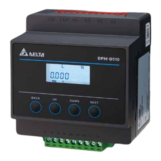
Delta Din-rail Power Meter DPM-D510
User Manual
www.deltaww.com
Advertisement
Chapters

Related Manuals for Delta DPM-D510


Summary of Contents for Delta DPM-D510
- Page 1 Mail: Sales.IA.RU@deltaww.com TEL: +7 495 644 3240 Delta Electronics ( Americas ) Ltd. USA: Delta Greentech Elektronik San. Ltd. Sti. ( Turkey ) 5101 Davis Drive, Research Triangle Park, NC 27709, U.S.A. Turkey: TEL: +1-919-767-3813 / FAX: +1-919-767-3969 Şerifali Mah. Hendem Cad. Kule Sok. No:16-A 34775 Ümraniye –...
- Page 2 Delta Din-rail Power Meter DPM-D510 User Manual Revision History Ve r s i o n R e v i s i o n D a t e T h e f i r s t v e r s i o n w a s p u b l i s h e d .
-
Page 4: Table Of Contents
Delta Din-rail Power Meter DPM-D510 User Manual Table of Contents Chapter 1 Product Introduction Preface ....................1-2 Overview ................... 1-2 Safety Precautions ................1-3 Chapter 2 Product Specifications Electrical characteristics ..............2-2 Communications Specifications ............2-3 Operating the Display ................2-4 2.1.1 Menu Tree .................. - Page 5 4.2.1 Password Setup (PASS) ..............4-3 4.2.2 Communication Setup (COM) ............4-4 4.2.3 Wiring Type (tyPE) ................ 4-6 4.2.4 VT and CT Setup (VT CT) ............... 4-6 4.2.5 Reset (rSt) .................. 4-8 4.2.6 Edit Password (PCHG) ..............4-9 4.2.7 Meter Information (INFO) .............. 4-9 Chapter 5 Parameters and Funcitons Overview of Parameters ..............
-
Page 6: Chapter1 Product Introduction
Chapter1 Product Introduction Table of Contents Preface ....................1-2 Overview ..................... 1-2 Safety Precautions ................1-3 1 - 1... -
Page 7: Preface
Thank you for choosing this product. This manual provides installation instructions for the DPM-D510 power meter. The multifunction power meter DPM-D510 is an obvious choice for any application in terms of power monitoring and control for sectors such as power system, industrial mining supply company, and public facility. -
Page 8: Safety Precautions
C h a p t e r 1 P r o d u c t I n t r o d u c t i o n Safety Precautions Installation Notes Install the power meter according to instructions on the manual. Use appropriate ... - Page 9 D e l t a D i n - r a i l P o we r M e t e r D P M - D 5 1 0 U s e r M a n u a l Maintenance and Inspection Notes ...
- Page 10 Chapter2 Specifications Table of Contents Electrical Characteristics ..............2-2 Communications Specifications ............2-3 Operating the Display ................2-4 2.1.1 Menu Tree ..................2-5 Dimensions ..................2-7 2 - 1...
-
Page 11: Electrical Characteristics
D e l ta D i n - r a i l P o we r M e t e r D P M - D 5 1 0 U s e r M a n u a l 2.1 Electrical Characteristics Measurement Accuracy Voltage, Real... -
Page 12: Communications Specifications
C h a p t e r 2 Sp e c i f i c a t i o n s -30 °C ~ +70°C(-22°F ~ +158°F) Storage temperature Relative Humidity 5 ~ 95% RH Altitude Below 2000 meters Pollution level *Meet the requirements of IEC62053-22 with accurate range: 50mA~ Display Screen Type... -
Page 13: Operating The Display
D e l ta D i n - r a i l P o we r M e t e r D P M - D 5 1 0 U s e r M a n u a l 2.3 Operating the Display DPM-D510 : Home page display:... -
Page 14: Menu Tree
C h a p t e r 2 Sp e c i f i c a t i o n s 2.3.1 Menu Tree DPM-D510: Meter Configuration 2 - 5... - Page 15 D e l ta D i n - r a i l P o we r M e t e r D P M - D 5 1 0 U s e r M a n u a l Display (Reversed active/ reactive/ apparent energy are supported by firmware version 1.02 and after.) ...
-
Page 16: Dimensions
Reactive Power Reactive Power Firmware Version Apparent Power dAtE Apparent Power Date Energy nonE Energy No reset PASS Password Reset default values Communication Reset energy values tyPE Connection type 2.4 Dimensions DPM-D510 Unit: mm Function VOLTAGE CURRENT 2 - 7... - Page 17 1A ~ 5A RS-485 -7 ~ +12 VDC Wiring Descriptions DPM-D510: AC:100~240V 250 mA fuse: Either positive or negative charge can be used on L1/+ and L2/-. When using a neutral wire for AC power, ※ you need to connect the neutral wire to the L2/-.
-
Page 18: Chapter 3 Installation
Chapter 3 Installation Table of Contents Installation ..................3-2 3.1.1 Installation Environment ..............3-2 3.1.2 Danger ..................3-2 3.1.3 Installation Notes ................3-6 Basic Checks ..................3-7 Wiring ....................3-8 3.3.1 Wiring Diagrams ................3-8 3.3.2 Communication Characteristics............3-10 3 - 1... -
Page 19: Installation Environment
Some storage suggestions are listed below. Store the power meter in a clean, dry, and controlled environment. Store DPM-D510 in an ambient temperature range of -30 ~ 70°C (-22 ~ 158°F). Store in a relative humidity range of 5–95%, non-condensing. - Page 20 EN DPM-D510 Multi-functional Power Meter series are used for electric power distribution(electric system) control, suitable for measurement of CATIII system. FR Les séries de wattmètres multifonctionnels DPM-D510 sont utilisées pour le contrôle de la distribution d'énergie électrique (système électrique), adaptées à la mesure du système CATIII.
- Page 21 D e l t a D i n - r a i l P o we r M e t e r D P M - D 5 1 0 U s e r M a n u a l FR ...
- Page 22 C h a p t e r 3 I n s t a l l a t i o n EN Do not use Do not use liquid containing acid and alkali on the power meter. FR Ne pas utiliser N'utilisez pas de liquide contenant de l'acide et des alcalis sur le wattmètre. EN ...
-
Page 23: Installation Notes
D e l t a D i n - r a i l P o we r M e t e r D P M - D 5 1 0 U s e r M a n u a l FR ... -
Page 24: Basic Checks
C h a p t e r 3 I n s t a l l a t i o n Step 3: Press to lock the plastic plate. 3.2 Basic Checks Items Contents Regularly check for mounting looseness where the power meter and device are connected. -
Page 25: Wiring
D e l t a D i n - r a i l P o we r M e t e r D P M - D 5 1 0 U s e r M a n u a l 3.3 Wiring 3.3.1 Wiring Diagrams To avoid electric shock, do not change the wiring when the power is on. - Page 26 C h a p t e r 3 I n s t a l l a t i o n Connection Diagrams 3PH3W, Δ connection, 3 CT, No PT 3PH3W, Δ connection, 2 CT, No PT 3PH3W, Δ connection, 3 CT, 2 PT 3PH4W, Y connection, 3 CT, No PT 3PH4W, Y connection, 3 CT, 3 PT 3PH4W, Y connection, 2 CT, 3 PT...
-
Page 27: Communication Characteristics
D e l t a D i n - r a i l P o we r M e t e r D P M - D 5 1 0 U s e r M a n u a l The following table lists the symbols used in the diagram. -
Page 28: Chapter 4 Operation
Chapter 4 Operation Table of Contents General Operation ................4-2 4.1.1 Setting Menu ................4-2 Setups ....................4-3 4.2.1 Password Setup (PASS) ..............4-3 4.2.2 Communication Setup (COM) ............4-4 4.2.3 Wiring Type (tyPE) ................ 4-6 4.2.4 VT and CT Setup (VT CT) ............... 4-6 4.2.5 Reset (rSt) ................... -
Page 29: General Operation
D e l t a D i n - r a i l P o we r M e t e r D P M - D 5 1 0 U s e r M a n u a l 4.1 General Operation 4.1.1 Setting Menu... -
Page 30: Setups
C h a p t e r 4 O p e r a t i o n 4.2 Setups 4.2.1 Password Setup (PASS) Password: before using power meter, you need to enter the password (default 0000) Steps: Press NEXT key till the first digit starts blinking Use UP and DOWN keys to select the first digit of the password Press NEXT key to confirm the selected digit and you can start to set the next digit Repeat steps 2-3 till you complete the setting of the 4 digit password. -
Page 31: Communication Setup (Com)
D e l t a D i n - r a i l P o we r M e t e r D P M - D 5 1 0 U s e r M a n u a l 4.2.2 Communication Setup (COM) Address (Addr): device ID;... - Page 32 C h a p t e r 4 O p e r a t i o n 4 - 5...
-
Page 33: Wiring Type (Type)
D e l t a D i n - r a i l P o we r M e t e r D P M - D 5 1 0 U s e r M a n u a l 4.2.3 Wiring Type (tyPE) Connection types: options are one-phase two-wire (1P2W), one-phase three-wire (1P3W), three-phase... - Page 34 C h a p t e r 4 O p e r a t i o n Steps: When VT CT is shown on the display, press NEXT key to enter the setting menu under VT CT and VT would be shown on the display. Use UP and DOWN keys to select the number of VT (VT no.) and CT (CT no.), VT ratio (VT Pri / VT SEC), CT ratio (CT Pri / CT SEC).
-
Page 35: Reset (Rst)
D e l t a D i n - r a i l P o we r M e t e r D P M - D 5 1 0 U s e r M a n u a l 4.2.5 Reset (rSt) No action (nonE): do not reset. -
Page 36: Edit Password (Pchg)
C h a p t e r 4 O p e r a t i o n 4.2.6 Edit Password (PCHG) Edit the password (default 0000) Steps: Press NEXT key till the first digit starts blinking Use UP and DOWN keys to select the first digit of the password Press NEXT key to confirm the setting and start to set the next digital input. - Page 37 D e l t a D i n - r a i l P o we r M e t e r D P M - D 5 1 0 U s e r M a n u a l ...
- Page 38 Chapter 5 Parameters and Functions Table of Contents Overview of Parameters ..............5-2 Modbus Communication ..............5-7 5.2.1 Supported Modbus Function Codes ..........5-7 5.2.2 Modbus Communication Protocol ............. 5-8 5 - 1...
-
Page 39: Overview Of Parameters
M an ua l D e l t a D i n - r a i l P o we r M e t e r D P M - D 5 1 0 U s e r 5.1 Overview of Parameters Modbus Data Address... - Page 40 Ch ap te r 5 Para me ters a nd Func tio ns 0: 3CT3PT 1: 3CT2PT 2: 3CT0PT 3: 2CT3PT Transformer 40019 4: 2CT2PT word quantities 5: 2CT0PT 6: 1CT3PT 7:1CT2PT 8:1CT0PT 40020 Reserved 40021 Timeout 1 – 99 word Second 40022 Reserved...
- Page 41 M an ua l D e l t a D i n - r a i l P o we r M e t e r D P M - D 5 1 0 U s e r 40263 Average phase 0.000 –...
- Page 42 Ch ap te r 5 Para me ters a nd Func tio ns 40294 40295 Three–phase average 0.000 – 99999.999 float current 40296 40297 Neutral line current 0.000 – 99999.999 float 40298 40299 Phase A current 0.00 – 99.99 float unbalance 40300 40301...
- Page 43 M an ua l D e l t a D i n - r a i l P o we r M e t e r D P M - D 5 1 0 U s e r 40323 Frequency 0.0000 –...
-
Page 44: Modbus Communication
Ch ap te r 5 Para me ters a nd Func tio ns - phase delivered 40350 40351 Active energy of three - phase received (Supported by 0x00000000 – 0xFFFFFFFF unit 40352 firmware version 1.02 and after) 40353 Reactive energy of three - phase 0x00000000 –... -
Page 45: Modbus Communication Protocol
M an ua l D e l t a D i n - r a i l P o we r M e t e r D P M - D 5 1 0 U s e r 5.2.2 Modbus Communication Protocol Modbus RTU mode is adopted with Modbus Master sending out the Request, in which the Function Code uses 0x03 to request response from Slave to correspond to values in Modbus address. - Page 46 Ch ap te r 5 Para me ters a nd Func tio ns Write: Example: For Modbus Master, such as PLC or data collector, it uses Modbus protocol to get the value of CT setting (Register address 0x000E) on the power meter (Modbus Slave) (Slave address 0x1). The register value is 1000.
- Page 47 M an ua l D e l t a D i n - r a i l P o we r M e t e r D P M - D 5 1 0 U s e r After receiving response from the power meter, Modbus Master acquires the value of currents from the primary-side current transformer (register address 0x000E), which is 1000 (0x3E8).
- Page 48 Chapter 6 Error Codes Table of Contents Error Codes ..................6-2 6 - 1...
- Page 49 D e l t a D i n - r a i l P o we r M e t e r D P M - D 5 1 0 U s e r M a n u a l 6.1 Error Codes When an error occurs during operation, the power monitor sends an error code through Modbus.
- Page 50 12 A Appendix A Accessories Table of Contents DCTMC Series ..................A-2 DCTCS Series ..................A-3 DCT1000 Series ................... A-4 DCT2000 Series ................... A-6 A- 1...
-
Page 51: Dctmc Series
D e l t a D i n - r a i l P o we r M e t e r D P M - D 5 1 0 U s e r M a n u a l When measured current is higher than the rated specification for the device, use of an external current transformer (CT) is necessary. -
Page 52: Dctcs Series
A p p e n d i x A A c c e s o r i e s A.2 DCTCS Series Rated External Size of Measurement Primary Secondary Model Type Burden Dimension*1 Opening*1 Accuracy Current Current (VA) (mm) (mm) DCT-CS010-5 100A 1000... -
Page 53: Dct1000 Series
D e l t a D i n - r a i l P o we r M e t e r D P M - D 5 1 0 U s e r M a n u a l A.3 DCT1000 Series Electromagnetic Compatibility: CE-marking, IEC61869-2. - Page 54 A p p e n d i x A A c c e s o r i e s Model Dimension (mm) Number External Dimension: DCT-S301C 90 x 40 x 111 Size of Opening: 21 x 32 DCT-S211C DCT-S221C DCT-S231C External Dimension: 116.5 x 52 x 147 DCT-S241C Size of Opening: 50 x 80...
-
Page 55: Dct2000 Series
D e l t a D i n - r a i l P o we r M e t e r D P M - D 5 1 0 U s e r M a n u a l A.4 DCT2000 Series Electromagnetic Compatibility: UL, UL2808. - Page 56 A p p e n d i x A A c c e s o r i e s Model Dimension (mm) Number External Dimension: DCT-S231B 115 x 57 x 158 DCT-S241B Size of Opening: 50 x 80 DCT-S251B DCT-S261B DCT-S2C1B DCT-S271B A - 7...
- Page 57 D e l t a D i n - r a i l P o we r M e t e r D P M - D 5 1 0 U s e r M a n u a l MEMO A - 8...