Table of Contents
Advertisement
Quick Links
Advertisement
Table of Contents

Related Manuals for Alcatel Speed Touch Wireless


Summary of Contents for Alcatel Speed Touch Wireless
- Page 1 SPEED TOUCH WIRELESS User Manual 3EC 17766 AAAA TCZZA Ed. 01...
- Page 2 BD F aa -PreRL Short Title CD-UG STWire R1.0 All rights reserved. Passing on and copying of this document, use and communication of its contents not permitted without written authorization from Alcatel. 2 / 362 3EC 17766 AAAA TCZZA Ed. 01...
-
Page 3: Table Of Contents
........Get Acquainted with your Speed Touch Wireless . - Page 4 Contents 5.3.2 Bridging Entries ........Advanced Bridging Concepts .
- Page 5 ........10.2 The Speed Touch Wireless Phonebook ......
- Page 6 ......12.2 Configuring the Speed Touch Wireless DNS Server ....
- Page 7 ..........Maintenance - Speed Touch Wireless Command Line Interface .
- Page 8 Contents 8 / 362 3EC 17766 AAAA TCZZA Ed. 01...
- Page 9 With download speeds up to 8 Mega bits per seconds (Mbps) the Speed Touch Wireless is around 200 times faster than present day modems. This superior Alcatel ADSL technology outperforms all similar products on the market.
- Page 10 CAUTION: indicates that failure to follow the directions could result in damage to equipment or loss of information. Trademarks The following trademarks are used in this document: Speed Touch is a trademark of the Alcatel Company " Netscape and Netscape Navigator are registered "...
- Page 11 " line. However, your SP might prefer other values. User Manual updates Due to the continuous evolution of the Alcatel ADSL technology, existing products are often upgraded. Alcatel documentation changes accordingly. For more information on the newest technological breakdowns and documents, please consult our Alcatel web site at: http://www.alcatel.com...
- Page 12 12 / 362 3EC 17766 AAAA TCZZA Ed. 01...
-
Page 13: Speed Touch Wireless Quick Guide
1 Speed Touch Wireless Quick Guide 1 Speed Touch Wireless Quick Guide Aim of this Quick Guide Use this chapter to quickly connect your STWireless to the Internet. In this chapter Topic Get Acquainted with your STWireless STWireless Installation 13 / 362... -
Page 14: Get Acquainted With Your Speed Touch Wireless
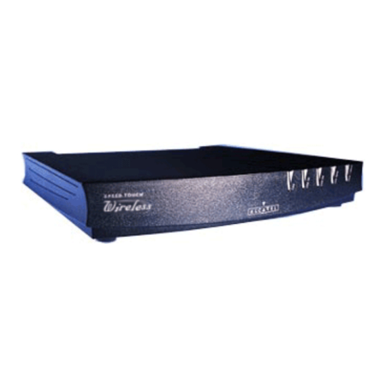
1 Speed Touch Wireless Quick Guide Get Acquainted with your Speed Touch Wireless Delivery check Check your STWireless package for the following items: The Speed Touch Wireless " 1 Power supply adapter with 2m (6.56ft.) connecting cable " 2m Ethernet/ATMF straight through cable (RJ45/RJ45) "... - Page 15 1 Speed Touch Wireless Quick Guide Your STWireless Your STWireless ADSL router is presented in a slim line box: For a detailed information and a LED description, refer to Appendix D. POTS vs. ISDN Ensure you have the correct STWireless: A POTS STWireless, connecting to an analog POTS line "...
-
Page 16: Speed Touch Wireless Installation
1 Speed Touch Wireless Quick Guide Speed Touch Wireless Installation Aim of this section Execute the steps in this section and in no time you are on the Internet. In this section Topic What you Need 1.2.1 STWireless Connections 1.2.2 Check your SP's Service Offerings 1.2.3... -
Page 17: What You Need
1 Speed Touch Wireless Quick Guide 1.2.1 What you Need ADSL and telephone ADSL service must be enabled on your telephone line. service You need a central splitter, or distributed filters for decoupling ADSL, and telephone signals. For more information, refer to Appendix B. -
Page 18: Stwireless Connections
1 Speed Touch Wireless Quick Guide 1.2.2 STWireless Connections You must connect The ADSL Port (Line) " The Power Port (DC). " After performing these steps you can turn on your STWireless. Proceed then with connecting: Your WLAN clients "... - Page 19 1 Speed Touch Wireless Quick Guide Connecting WLAN Preconditions: " clients Make sure your STWireless is turned on and finished its Power On Self Test (POST). The (portable) PCs, intended to be connected to the STWireless, must have a WLAN adapter readily installed, and must be configured as DHCP client.
- Page 20 1 Speed Touch Wireless Quick Guide Check your wiring After you finished wiring the STWireless, the result should resemble the following figure: Note: WLAN client PCs are not shown in the above figure. 20 / 362 3EC 17766 AAAA TCZZA Ed. 01...
-
Page 21: Check Your Service Provider's Offering
1 Speed Touch Wireless Quick Guide 1.2.3 Check your Service Provider's Offering Service offering The SP provides at least the following information: The Virtual Channel Identifier, that is, the VPI/VCI value of the " VC to use on the ADSL line The Connection Service supported on this VC "... -
Page 22: Select An Stwireless Packet Service
1 Speed Touch Wireless Quick Guide 1.2.4 Select an STWireless Packet Service Connection service As soon as you know the Connection Service on a VC, you can attach a Packet Service to it. Following combinations are possible: Connection Service Packet Service... -
Page 23: Configure Your Stwireless (If Necessary)
1 Speed Touch Wireless Quick Guide 1.2.5 Configure your STWireless (If Necessary) STWireless access In most cases your STWireless provides instant Internet connectivity as it features well chosen defaults In the exceptional cases, additional, or advanced configurations are desired, the STWireless offers various access methods: Its web pages (See chapter 18) "... -
Page 24: Surf The Internet
1 Speed Touch Wireless Quick Guide 1.2.6 Surf the Internet Finishing setup After wiring (and optionally configuring) your STWireless, you are ready to surf the Internet. Access Types Depending on the used packet service(s), you can have: Always On Access "... -
Page 25: Detailed Stwireless Information
1 Speed Touch Wireless Quick Guide 1.2.7 Detailed STWireless Information The STWireless is more Use the following parts (marked grey) of this manual to explore STWireless's advanced features: than just" an ADSL router Speed Touch Wireless Quick Guide Speed Touch Wireless Wiring Guide... - Page 26 1 Speed Touch Wireless Quick Guide 26 / 362 3EC 17766 AAAA TCZZA Ed. 01...
- Page 27 Speed Touch Wireless Wiring Guide 27 / 362 3EC 17766 AAAA TCZZA Ed. 01...
- Page 28 28 / 362 3EC 17766 AAAA TCZZA Ed. 01...
-
Page 29: Wiring Guide - Adsl, Power And Console
2 Wiring Guide - ADSL, Power and Console 2 Wiring Guide - ADSL, Power and Console In this chapter Topic Locating Ports Connecting the ADSL Port Connecting the Power Adapter Connecting the Serial Port (Optional) 29 / 362 3EC 17766 AAAA TCZZA Ed. 01... -
Page 30: Locating Ports
2 Wiring Guide - ADSL, Power and Console Locating Ports Port description Following ports are used: 3 : ADSL line port, marked LINE" " 4 : Power socket, market DC" " 5 : Serial port, marked Console". " 30 / 362 3EC 17766 AAAA TCZZA Ed. -
Page 31: Connecting The Adsl Port
2 Wiring Guide - ADSL, Power and Console Connecting the ADSL Port Important information Read appendix B before you connect the STWireless. Preconditions prior to A central splitter, or distributed filters for decoupling ADSL and POTS, or ISDN signals must be installed. Crossover adapters connecting might be required. -
Page 32: Connecting The Power Adapter
2 Wiring Guide - ADSL, Power and Console Connecting the Power Adapter Introduction The STWireless is delivered with a modular external power adapter converting the AC mains to 9V /1A unregulated output voltage. Power adapter types Check if the power adapter included in the STWireless package is compatible with your local electrical power specifications. -
Page 33: Connecting The Serial Port (Optional)
2 Wiring Guide - ADSL, Power and Console Connecting the Serial Port (Optional) Serial access Like most routers, the STWireless carries a serial port on its rear panel, featuring access from a remote host via a modem connection, or local access from a terminal. Requirements for using For access via the serial port, you must have the following: the serial access... - Page 34 2 Wiring Guide - ADSL, Power and Console 34 / 362 3EC 17766 AAAA TCZZA Ed. 01...
-
Page 35: Wiring Guide - Network Connections
3 Wiring Guide - Network Connections 3 Wiring Guide - Network Connections In this chapter Topic Connecting Wireless LAN LAN Cables Connecting Wired Ethernet (Optional) Wired Ethernet vs. WLAN Connectivity 35 / 362 3EC 17766 AAAA TCZZA Ed. 01... -
Page 36: Connecting Wireless Lan
3 Wiring Guide - Network Connections Connecting Wireless LAN Introduction Next to the single Ethernet port, enabling wired LAN connectivity, the STWireless contains a Wireless LAN (WLAN) hub. This WLAN hub allows wireless connection of several devices to the public network, e.g. the Internet. The same technology enables these devices to communicate with each other in a locally mobile fashion, without the need of a wired LAN environment. - Page 37 3 Wiring Guide - Network Connections WLAN client Only WLAN client adapters compliant to IEEE802.11b DSSS, will be able to communicate with the STWireless, and hence, with requirements other members of the STWireless WLAN environment. It is advisable that the WLAN client adapter is WECA Wi Fi certified to ensure smooth interoperability.
- Page 38 3 Wiring Guide - Network Connections Result After performing the last step of the procedure, you should be able to contact the STWireless, e.g. pinging 10.0.0.138, or open the STWireless web pages. See chapter 18 for more information. Configuration of your As soon you have connectivity with the STWireless you are able to configure the STWireless WLAN parameters via the web pages.
-
Page 39: Lan Cables
3 Wiring Guide - Network Connections LAN Cables Included LAN cable In your STWireless package, a full wired straight through RJ45/RJ45 cable, further referred to as LAN cable, is included. Using LAN cables You can use LAN cables other than the one provided in the box, e.g. -
Page 40: Connecting Wired Ethernet (Optionally)
3 Wiring Guide - Network Connections Connecting Wired Ethernet (Optionally) In this section Topic The Ethernet Port on your STWireless 3.3.1 Wired Single PC Connection 3.3.2 Wired Ethernet LAN 3.3.2 40 / 362 3EC 17766 AAAA TCZZA Ed. 01... -
Page 41: The Ethernet Port On Your Stwireless
3 Wiring Guide - Network Connections 3.3.1 The Ethernet Port on your STWireless Ethernet interface The STWireless Ethernet port 1 is a 10Base T Half Duplex Ethernet interface of type MDI X, connecting to either a single PC, or a workgroup hub. Ethernet on your PC Your PC may have a built in Ethernet port. -
Page 42: Wired Single Pc Connection
3 Wiring Guide - Network Connections 3.3.2 Wired Single PC Connection Single PC configuration In this configuration the STWireless is connected to a single PC. Procedure Proceed as indicated in the following figure to connect your STWireless to a single PC: 10 Base T MDI X 42 / 362... -
Page 43: Wired Ethernet Lan
3 Wiring Guide - Network Connections 3.3.3 Wired Ethernet LAN Procedure Proceed as indicated in the following figure to make the connections for a wired LAN: 10Base T MDI X Cascading Repeating Hubs Because of the limitations of Repeating Ethernet V2.0/IEEE802.3 hubs, the maximum number of repeating hubs cascaded in your CAUTION LAN is four. -
Page 44: Wired Ethernet Vs. Wlan Connectivity
3 Wiring Guide - Network Connections Wired Ethernet vs. WLAN Connectivity Wireless vs. Wired The STWireless makes no difference between wired Ethernet and WLAN clients. All connected PCs, whether these are connected via LANs the STWireless Ethernet port, or connected via joining the WLAN SSID, share the same (sub)network. -
Page 45: Data Services
Speed Touch Wireless Data Services 45 / 362 3EC 17766 AAAA TCZZA Ed. 01... - Page 46 46 / 362 3EC 17766 AAAA TCZZA Ed. 01...
-
Page 47: Data Services - Packet Services
4 Data Services - Packet Services 4 Data Services - Packet Services Introduction This chapter is about selecting the appropriate packet service for your application. In this chapter Topic Supported Packet Services Packet Services at a Glance Internet & Corporate Access vs. LAN to LAN Interconnection Direct Networking vs. -
Page 48: Supported Packet Services
4 Data Services - Packet Services Supported Packet Services What is a packet A packet service can be defined as: service ? The actions that need to be performed on every data packet in order to filter or forward packets to the next device in the communication chain."... -
Page 49: Packet Services At A Glance
4 Data Services - Packet Services Packet Services at a Glance In this section IEEE 802.1D Transparent Bridging " MAC Encapsulated Routing " PPPoA to PPTP Relaying " PPP & IP Routing " CIP & IP Routing " Selection Criteria "... - Page 50 4 Data Services - Packet Services PPP & IP Routing Point to Point Protocol (PPP) combined with IP routing is the technology of choice to create a small IP based home (W)LAN. Similar to PPPoA/PPTP , it provides a session concept. Additionally, IP routing combined with NAPT allows to multiplex users into a single VC.
- Page 51 4 Data Services - Packet Services Resumé All STWireless's packet services can be summarized in the following table: Port Packet Service Protocol Chapter 10Base T IEEE 802.1D Bridging Multiprotocol Ethernet MAC Encapsulated Routing TCP/IP PPPoA to PPTP Relaying TCP/IP , IPX/SPX, NETBEUI PPP &...
-
Page 52: Internet & Corporate Intranet Access Vs. Lan To Lan Interconnection
4 Data Services - Packet Services Internet & Corporate Intranet Access vs. LAN to LAN Interconnection Exemplary applications This manual highlights the two most prominent ADSL applications: using ADSL High speed Internet access, or corporate Intranet access " Private Wide Area Network (WAN) / Local Area Network (LAN) "... -
Page 53: Direct Networking Vs. Dial Up Networking
4 Data Services - Packet Services Direct Networking vs. Dial up Networking In this section What is Direct Networking " Comparison with LAN Networking " What is Dial Up Networking " STWireless & Networking " Ethernet Port(s) & Networking. " What is direct Direct networking refers to how the network connection is experienced by the user. - Page 54 4 Data Services - Packet Services Ethernet port(s) & Following scenarios are available: networking Direct and continuous connectivity is accomplished via " the IEEE 802.1D transparent databridge, in the STWireless. See chapter 5 for more information. MER provides continuous connectivity "...
-
Page 55: Adsl Modem Vs. Adsl Gateway
4 Data Services - Packet Services ADSL Modem vs. ADSL Gateway Introduction In the configuration where multiple PCs reside on a common LAN, they must share a gateway for specific services. The most important service is ADSL for accessing the outside world. The STWireless can be used as a fast ADSL modem, leaving the gateway tasks to another (W)LAN member. -
Page 56: Adsl Modem Model
4 Data Services - Packet Services 4.5.1 ADSL Modem Model ADSL modem model The STWireless in this role, provides connectivity to either a single PC: or to a dedicated home gateway: ADSL Line Bit pipe Single PC Or to a dedicated home gateway: ADSL Line Bit pipe Home Gateway... -
Page 57: Adsl Gateway Model
4 Data Services - Packet Services 4.5.2 ADSL Gateway Model ADSL gateway model The gateway to access the outside world can be a dedicated PC as shown in subsection 4.5.1. However, the STWireless itself is designed to act as a cost effective ADSL gateway. - Page 58 4 Data Services - Packet Services 58 / 362 3EC 17766 AAAA TCZZA Ed. 01...
-
Page 59: Data Services - Transparent Bridging
5 Data Services - Transparent Bridging 5 Data Services - Transparent Bridging Introduction The STWireless IEEE802.1D Transparent Bridging packet service offers complete protocol transparency and has inherent configuration simplicity. Yet it provides excellent forwarding performance. In this chapter Topic Preparatory Steps Using Bridging Bridging Configuration Advanced Bridging Concepts... -
Page 60: Preparatory Steps
" Is simple to configure and easy to use " Is a true multiprotocol device " In the Alcatel implementation, has no performance limitations " Has no theoretical constraints on the number of attached " users (There is a practical limit to achieve a reasonable performance, e.g. - Page 61 5 Data Services - Transparent Bridging TCP/IP For TCP/IP , your SP will assign you either static IP parameters (per PC), or will instruct you to enable DHCP on your PC(s). Transparent Bridging and DHCP If the SP requires you to use DHCP on your local PC(s), you must disable the STWireless DHCP server.
-
Page 62: Using Bridging
5 Data Services - Transparent Bridging Using Bridging Using Bridging From this point on, using Transparent Bridging is rather straight forward. Turn on both your STWireless and PC, start your Web browser and you are on the Internet. Always on and This form of remote network access is sometimes referred to as Always on". -
Page 63: Bridging Configuration
5 Data Services - Transparent Bridging Bridging Configuration Introduction The STWireless allows local configurations via the STWireless web pages. This section describes the configuration of Bridging entries, and the use of the 'Bridging' web page. In this section Topic Bridging Phonebook Entries 5.3.1 Bridging Entries 5.3.2... -
Page 64: Bridging Phonebook Entries
5 Data Services - Transparent Bridging 5.3.1 Bridging Phonebook Entries Bridging phonebook Central to the STWireless VC pool management, is the 'Phonebook' web page. entries The STWireless in its default state features the following Bridging/MER related phonebook entries: Note: Both Bridging and MER share the same type of phonebook entries, i.e. -
Page 65: Bridging Entries
5 Data Services - Transparent Bridging 5.3.2 Bridging Entries In this subsection The STWireless 'Bridging' Web Page " The 'Bridging Ports' Table " 'Bridging Ports' Table Components " The 'Aging' Box " Adding Bridging Entries " Deleting Bridging Entries. " The STWireless Clicking in the left pane of the STWireless web pages,... - Page 66 5 Data Services - Transparent Bridging The 'Bridging Ports' The following figure shows the 'Bridging Ports' table in its default state: table 'Bridging Ports' table The following fields are shown: components Field Description Intf Allows you to choose an interface name for the Bridge interface.
- Page 67 5 Data Services - Transparent Bridging Field Description Encap Refers to the encapsulation, and decapsulation of Ethernet, or IEEE 802.3 frames in/from AAL5/ATM. The STWireless is compliant with RFC 1483 Multiprotocol Encapsulation over ATM Adaptation Layer 5" and supports both the LLC/SNAP method and the VC MUX method for Bridged Ethernet V2.0/IEEE 802.3 PDUs.
- Page 68 5 Data Services - Transparent Bridging Adding Bridging Proceed as follows: entries Step Action and Description Browse to the 'Bridging' web page. The bottom row of the table allows addition of a new entry. In the 'Destination' column of the bottom row, click and select the Bridging entry you want to add to the table.
-
Page 69: Advanced Bridging Concepts
5 Data Services - Transparent Bridging Advanced Bridging Concepts Bridging Bridging is a LAN technology that transparently relays Ethernet frames between Bridging ports. Depending on the destination MAC addresses of Ethernet frames, the bridge makes decisions whether to forward or discard frames. Central to the operation of a databridge is its filtering database. -
Page 70: Stwireless Bridge Operation
5 Data Services - Transparent Bridging 5.4.1 STWireless Bridge Operation Introduction to bridge This section describes how the STWireless bridge operates. All of these operations have an impact on the entries in the filtering operation database of the bridge. One of the characteristics of a databridge is the number of supported Bridge ports. - Page 71 5 Data Services - Transparent Bridging Learning If the bridge is turned on, the filtering database is empty. Over time it is filled with entries via the learning mechanism. Ethernet frames arriving on any port are inspected for their source MAC address and put into the filtering database together with the port ID the frames arrived on.
- Page 72 Indeed, it makes little sense to forward the frame on this port as the destination is directly connected to the source. Isolation The Alcatel Multiport bridge in the STWireless provides isolation between remote ports. i.e. Frames (including broadcasts) arriving via ADSL/ATM ports will never be forwarded/flooded to another ADSL/ATM port.
-
Page 73: Stwireless 'Bridge Data' Web Page
5 Data Services - Transparent Bridging 5.4.2 STWireless 'Bridge Data' Web Page Introduction Transparent Bridging relies completely on its filtering database for managing the traffic, passing through the bridge. This filtering database is accessible via the STWireless 'Bridging' web page, and allows you to overview all MAC layer entries. - Page 74 5 Data Services - Transparent Bridging Permanent MAC These are the MAC addresses that must always be resident inside the bridge, as stipulated in the IEEE802.1D standard: addresses The STWireless's own MAC address: " e.g. 00-80-9F-01-02-03 The Broadcast MAC address: "...
-
Page 75: Data Services - Mac Encapsulated Routing
6 Data Services - MAC Encapsulated Routing 6 Data Services - MAC Encapsulated Routing Introduction Via the STWireless MAC Encapsulated Routing packet service you can connect to an ADSL line supporting the ETHernet over ATM (ETHoA) connection service. In contrast to bridging though, packet filtering and forwarding is performed by the IP router of the STWireless and consequently inherits all the features that come with IP . -
Page 76: Preparatory Steps
6 Data Services - MAC Encapsulated Routing Preparatory Steps Features MAC Encapsulated Routing: Is instantly replaceable with an IEEE Transparent Bridge " Provides Always on type of connections and is " auto configurable if DHCP is enabled If used in combination with NAPT, allows multiple users to "... -
Page 77: Using Mer
6 Data Services - MAC Encapsulated Routing Using MER Using Bridging From this point on, using MER is rather straight forward. Turn on both your STWireless and PCs, and your connected to the remote access router. Always on and As MER presents itself as a Bridge, the connection behaves as for the Transparent Bridging packet service. -
Page 78: Mer Configuration
6 Data Services - MAC Encapsulated Routing MER Configuration Introduction The STWireless allows local configurations via the STWireless web pages. This section describes the configuration of MER entries, and the use of the 'MER' web page. In this section Topic MER Phonebook Entries 6.3.1 MER Entries... -
Page 79: Mer Phonebook Entries
6 Data Services - MAC Encapsulated Routing 6.3.1 MER Phonebook Entries MER phonebook Central to the STWireless VC pool management, is the 'Phonebook' web page. entries The STWireless in its default state features the following MER related phonebook entries: Note: Both MER and Bridging share the same type of phonebook entries, i.e. -
Page 80: Mer Entries
6 Data Services - MAC Encapsulated Routing 6.3.2 MER Entries The STWireless 'MER' Clicking in the left pane of the STWireless web pages, web page pops up the 'MER' web page (See section 18.2 for more information): The 'MER Connections' The following figure shows the 'MER Connections' table: table 80 / 362... - Page 81 6 Data Services - MAC Encapsulated Routing 'MER Connections' The following fields are shown: table components Field Description Click the button next to the MER connection you want to configure. Selected MER connections are indicated by a yellow bar, and a button which is lit.
- Page 82 6 Data Services - MAC Encapsulated Routing The 'MER Settings' The following figure shows the 'MER Settings' table: table 'MER Settings' table The following fields are shown: components Field Description Interface Allows to enter an interface name for the MER connection. Note: You don't have to fill in a name for the MER interface.
- Page 83 6 Data Services - MAC Encapsulated Routing 'MER Interface The following fields are shown: Settings' table components Field Description IP Address Allows to enter a static IP address for the MER connection. Note: In case no IP address is entered, the MER connection will receive an IP address from the remote access server.
- Page 84 6 Data Services - MAC Encapsulated Routing Adding MER entries Proceed as follows: Step Action and Description Browse to the 'MER' web page. If the 'MAC Encapsulated Routing' table is empty, i.e. you are creating the first MER connection, proceed with step 3. If you want to add a MER connection in addition to existing MER connections (see 'MAC Encapsulated Routing' table), click...
- Page 85 6 Data Services - MAC Encapsulated Routing Maximum number of The STWireless can manage up to 12 MER connections simultaneously. This can be achieved by deleting all other packet MER connections service entries. Note: Check with your ASP , or corporate whether multiple end to end connectivity is enabled.
-
Page 86: Advanced Mer Concepts
6 Data Services - MAC Encapsulated Routing Advanced MER Concepts In this subsection MAC Encapsulated Routing " MER operation: From (W)LAN to STWireless's IP router " MER operation: From IP Router to MER " MER operation: From MER to WAN "... - Page 87 6 Data Services - MAC Encapsulated Routing MER Operation: from IP packets destinated for MER, can be subjected to NAPT, prior to end up in the appropriate MER interface STWireless's IP router to MER NAPT allows local (W)LAN PCs to share the single static, or dynamically obtained public IP address for the MER connection.
- Page 88 6 Data Services - MAC Encapsulated Routing 88 / 362 3EC 17766 AAAA TCZZA Ed. 01...
-
Page 89: Data Services - Pppoa To Pptp Relaying
7 Data Services - PPPoA to PPTP Relaying 7 Data Services - PPPoA to PPTP Relaying Introduction The STWireless PPPoA to PPTP Relaying packet service relays PPP frames, arriving via local IP tunnels to a previously selected VC, and vice versa. The PPP protocol that originates, or terminates in the locally attached PCs, offers a session concept, and provides security via identification, authentication and encryption. -
Page 90: Preparatory Steps
7 Data Services - PPPoA to PPTP Relaying Preparatory Steps Features PPPoA to PPTP Relaying: Provides standard Dial up" PPP behavior " Supports security via identification, authentication and " encryption Has multiprotocol support depending on the PPTP " implementation, e.g. for MS Windows: TCP/IP , IPX/SPX and NETBEUI Offers complete TCP/IP protocol transparency;... - Page 91 7 Data Services - PPPoA to PPTP Relaying PC(s) Your PC must support PPP and Point to Point Tunnelling Protocol (PPTP). e.g. All Microsoft Windows platforms support PPP and PPTP . TCP/IP Before you can establish PPTP tunnels, you must configure: An IP address in each PC which initiates a PPTP tunnel "...
-
Page 92: Configuring And Using A Pptp Connection
7 Data Services - PPPoA to PPTP Relaying Configuring and Using a PPTP Connection Introduction Before you can open a PPTP tunnel towards the STWireless, firstly you must initially configure a PPTP dial up connection on your PC. Once this PPTP dial up connection is configured, you can use it to open a PPPoA/PPTP connection to the remote side of the ADSL line. -
Page 93: Preparing Your Pc For Pppoa/Pptp
7 Data Services - PPPoA to PPTP Relaying 7.2.1 Preparing your PC for PPPoA/PPTP Creating a PPTP Most, if not all OSs provide a GUI guided procedure for the initial creation of a PPTP connection icon. connection icon The result of such creation is in most cases an icon, or entry in a folder, or a table, called 'RAS', 'Dial Up Networking', 'PPTP', 'Call sessions', etc. -
Page 94: Using Pptp Towards Your Stwireless
7 Data Services - PPPoA to PPTP Relaying 7.2.2 Using PPTP towards your STWireless Opening a session Depending on your OS, you can open a session by either double clicking the PPTP connection icon, or selecting it from a RAS table and clicking 'Dial Up', or 'Connect'. -
Page 95: Example : Ms Windows 98 Dial Up Networking
7 Data Services - PPPoA to PPTP Relaying Example : MS Windows 98 Dial Up Networking In this section The following overview summarizes the necessary steps to setup a Microsoft Windows 98 PC for the use of PPPoA to PPTP Relaying: Step Action Configure a Private IP address on your PC... -
Page 96: Create A New Dial Up Networking Icon
7 Data Services - PPPoA to PPTP Relaying 7.3.1 Create a New Dial Up Networking Icon Procedure Proceed as follows: Step Action and Description Double click the 'My Computer' icon on your desktop. Double click the 'Dial Up Networking' icon. Double click the 'Make New Connection' icon to activate the 'Make New Connection' wizard. - Page 97 7 Data Services - PPPoA to PPTP Relaying Step Action and Description In the first input field of the 'Make New Connection' window, type a name, or alias of the organization you are connecting to. Note: This name will appear below the Dial Up icon at the end of this procedure.
- Page 98 7 Data Services - PPPoA to PPTP Relaying Result A new icon with the name of the connection that you have just created, will be added to your 'Dial Up Networking' folder: Creating multiple Per destination you can create a unique icon. To do so, repeat the steps, starting with 3 of the previous procedure.
-
Page 99: Create A Shortcut On Your Desktop (Optional)
7 Data Services - PPPoA to PPTP Relaying 7.3.2 Create a Shortcut on your Desktop (Optional) Introduction To work comfortably with the Dial Up connection(s) you created, Windows 98 offers you the possibility to place a shortcut of the connection icon on your desktop. Shortcut procedure Proceed as follows: Step... -
Page 100: Open A Pppoa/Pptp Dial Up Session
7 Data Services - PPPoA to PPTP Relaying 7.3.3 Open a PPPoA/PPTP Dial Up Session Procedure Proceed as follows: Step Action and Description Double click the appropriate PPPoA/PPTP Dial Up icon in the 'Dial Up Networking' folder, or double click its shortcut on your desktop. The 'Connect To' window pops up Fill in your user name and password, according your user account at the ISP , or corporate. - Page 101 7 Data Services - PPPoA to PPTP Relaying While you are Once the PPPoA/PPTP Dial Up connection is established, you can find the MSDUN icon showing two PCs connected to each other in connected the system tray: The MSDUN icon symbolizes activity on the PPPoA/PPTP connection by flashing PC(s): A flashing Front"...
-
Page 102: Close A Pppoa/Pptp Dial Up Session In Use
7 Data Services - PPPoA to PPTP Relaying 7.3.4 Close a PPPoA/PPTP Dial Up Session in Use Procedure Proceed as follows: Step Action and Description If the Dial Up connection is minimized, click the MSDUN icon in the system tray: The 'Connected To' window pops up. -
Page 103: Pppoa/Pptp Configuration
7 Data Services - PPPoA to PPTP Relaying PPPoA/PPTP Configuration Introduction The STWireless allows local configuration via the STWireless web pages. This section describes the configuration of PPPoA/PPTP entries, and how to use the 'PPTP' web page. In this section Topic PPPoA/PPTP Phonebook Entries 7.4.1... -
Page 104: Pppoa/Pptp Phonebook Entries
7 Data Services - PPPoA to PPTP Relaying 7.4.1 PPPoA/PPTP Phonebook Entries PPTP phonebook Basic to the STWireless VC pool management, is the 'Phonebook' web page. entries The STWireless in its default state features the following PPP related phonebook entries: Note: Both PPPoA/PPTP and PPP &... -
Page 105: Pppoa/Pptp Active Connections
7 Data Services - PPPoA to PPTP Relaying 7.4.2 PPPoA/PPTP Active Connections In this subsection The STWireless 'PPTP' Web Page " The 'Active PPTP Connections' Table " 'Active PPTP Connections' Table Components " Configuring PPTP Profiles " The STWireless 'PPTP' Clicking in the left pane of the STWireless web pages, web page... - Page 106 7 Data Services - PPPoA to PPTP Relaying The 'Active PPTP The following figure shows the 'Active PPTP Connections' table: Connections' table 'Active PPTP The following fields are shown: Connections' table Field Description components Dial string Indicates the name you have chosen for the PPTP connection. Note: In your Dial Up application you are able to specify which PPTP connection is to be used by adding the appropriate Dial string, indicated here.
- Page 107 7 Data Services - PPPoA to PPTP Relaying Field Description HDLC In order to cope with these PPP frame differences, the STWireless adapts to the different formats on a 'per Framing connection' base. (continued) Additionally, the STWireless offers the following PPP/AAL5 format configuration options via the CLI if interoperability problems should arise (See section 7.5 for more information): Value...
-
Page 108: Customizing Pppoa/Pptp Connections
7 Data Services - PPPoA to PPTP Relaying Customizing PPPoA/PPTP Connections Introduction In this section the advanced configuration and use of PPPoA/PPTP connections is described. Firstly, this section deals with some concepts on the customization of PPPoA/PPTP connections. In this section Topic PPTP Phonebook Entries 7.5.1... -
Page 109: Pppoa/Pptp Phonebook Entries
7 Data Services - PPPoA to PPTP Relaying 7.5.1 PPPoA/PPTP Phonebook Entries Introduction To establish a PPPoA/PPTP session, all you need to do is opening a PPTP tunnel. However, this does only apply in the case only a single destination is reachable via one, or more VCs. -
Page 110: Single Destination
7 Data Services - PPPoA to PPTP Relaying 7.5.2 Single Destination Single destination If the 'VPN Server' field of the PPTP Dial Up application is left unchanged, i.e. only the IP address of the STWireless (or its host PPPoA/PPTP sessions name) is visible, the STWireless automatically chooses a free PPP phonebook entry from the Phonebook. -
Page 111: Multiple Destinations
7 Data Services - PPPoA to PPTP Relaying 7.5.3 Multiple Destinations Multiple destination Multiple SPs might be connected to your STWireless, e.g., your private ISP and your corporate. PPPoA/PPTP sessions In this case, the STWireless's PPP VCs can be split over both locations. - Page 112 PPP VCs and the locations. Example for Windows Proceed as follows to create an MS Windows 9x Dial Up Networking icon to the corporate 'Alcatel', which has to use the VC, named 'Alcatel_pptp': Step Action and Description Configure a PPP phonebook entry, named 'Alcatel_pptp', in the Phonebook as described in subsection 7.4.1.
- Page 113 In step 9 of the procedure (See section 7.3.1), you not only specify the VPN server, i.e. the STWireless, but also the VC 'Alcatel_pptp': Double click the 'Alcatel' icon to open the PPPoA/PPTP session. The following Dial Up window pops up: As you can see in the 'VPN Server' field, the VC, i.e.
- Page 114 The following figure shows an example of both single and multiple PPPoA/PPTP connections established simultaneously. INTERNET ATM Channels My ISP PPP RELAY Other Virtual Channels Local PPTP Tunnels 'Alcatel_pptp' Alcatel Remote LAN 114 / 362 3EC 17766 AAAA TCZZA Ed. 01...
-
Page 115: Restrictions On Using Specific Virtual Channels
7 Data Services - PPPoA to PPTP Relaying 7.5.4 Restrictions on Using Specific Virtual Channels Similar phonebook The STWireless will look for a match between the string, specified next to the VPN server's DNS hostname or IP address (in the names previous example the string 'Alcatel_pptp'). -
Page 116: Pptp Profiles
7 Data Services - PPPoA to PPTP Relaying 7.5.5 PPTP Profiles Introduction In most cases, the STWireless's PPP phonebook entries are ideally suited to make PPPoA/PPTP connections over the ADSL line. However, in case the remote access server demands specific configurations for PPPoA/PPTP , you can easily configure a PPTP profile via the CLI. -
Page 117: Advanced Pppoa/Pptp Concepts
7 Data Services - PPPoA to PPTP Relaying Advanced PPPoA/PPTP Concepts Introduction This section describes some advanced concepts of the STWireless's PPPoA to PPTP Relaying packet service. Topics Topic Point to Point Tunneling 7.6.1 Local Tunneling 7.6.2 PPPoA to PPTP Relaying (PPPoA/PPTP) 7.6.3 Simultaneous PPPoA/PPTP Sessions 7.6.4... -
Page 118: Point To Point Tunneling
7 Data Services - PPPoA to PPTP Relaying 7.6.1 Point to Point Tunneling What is Tunneling Tunneling is a technique that allows to transport certain protocols over a network, which is not designed for that purpose. Example: IPX Packets can be wrapped in IP , ready to be routed over an IP network. -
Page 119: Local Tunneling
7 Data Services - PPPoA to PPTP Relaying 7.6.2 Local Tunneling Tunneling from behind The STWireless allows local tunneling from behind an IP router: an IP router 172.16.0.2 IP Router Local PPTP tunnels Ethernet (W)LAN 172.16.0.1 10.0.0.138 10.0.0.1 IP Network 10 IP Network 172.16 172.16.0.3 This requires settings in both STWireless and PCs. -
Page 120: Pppoa To Pptp Relaying (Pppoa/Pptp)
7 Data Services - PPPoA to PPTP Relaying 7.6.3 PPPoA to PPTP Relaying (PPPoA/PPTP) What is PPPoA to PPTP By opening a PPPoA/PPTP session, PPTP tunnels are established between the STWireless and the PCs on your (W)LAN. Relaying These PPTP tunnels trigger the Relaying utility of the STWireless: it chooses a free VC from the pool of available free PPP phonebook entries and relays all PPP frames, sourced by the PPTP tunnel from the tunnel to the VC, and vice versa. -
Page 121: Simultaneous Pppoa/Pptp Sessions
7 Data Services - PPPoA to PPTP Relaying 7.6.4 Simultaneous PPPoA/PPTP Sessions Upper limit of PPTP tunneling does not influence your local communication; you can add as many hosts as your local network supports. simultaneous PPPoA/PPTP sessions However, there is an upper limit to the number of simultaneous outbound connections. - Page 122 7 Data Services - PPPoA to PPTP Relaying 122 / 362 3EC 17766 AAAA TCZZA Ed. 01...
-
Page 123: Data Services - Ppp & Ip Routing
8 Data Services - PPP & IP Routing 8 Data Services - PPP & IP Routing Introduction The STWireless features the PPP & IP Routing packet service. Via the PPP protocol an authenticated session is established with your SP . IP packets, arriving over the PPP connection, are forwarded by the IP router to PCs on your (W)LAN. -
Page 124: Preparatory Steps
8 Data Services - PPP & IP Routing Preparatory Steps Features PPP & IP Routing: Has an authenticated session concept: it supports " identification, authentication and autoconfiguration. Requires no session client on the PC(s), avoiding special " installation procedures Combined with NAPT, allows multiple users to share a single "... -
Page 125: Using Ppp & Ip Routing
8 Data Services - PPP & IP Routing Using PPP & IP Routing Always on, Dial in and Three methods exist to open a PPP: Dial on Demand PPP Dial in " sessions The PPP session is opened manually Always on "... - Page 126 8 Data Services - PPP & IP Routing Step Action and Description If applicable the 'Authentication' web page pops up: Enter user name and password in the appropriate fields. Click After identification and authentication, the 'PPP connections' web page reappears. While the STWireless tries to open the session, trying will appear in the 'State' field.
-
Page 127: Ppp Configuration
8 Data Services - PPP & IP Routing PPP Configuration Introduction The STWireless allows local configurations via its web pages. This section describes the enabling of PPP entries, and the use of the 'PPP' web page. Prior to be able to use the PPP entry, you must configure the PPP entry. -
Page 128: Ppp Phonebook Entries
8 Data Services - PPP & IP Routing 8.3.1 PPP Phonebook Entries PPP phonebook entries Central to the STWireless VC pool management, is the 'Phonebook' web page. The STWireless in its default configuration features the following PPP related phonebook entries: Note: Both PPP &... -
Page 129: Ppp Entries
8 Data Services - PPP & IP Routing 8.3.2 PPP Entries In this subsection The 'PPP' Web Page " The 'PPP Configuration' Table " 'PPP Configuration' Table Components " Adding PPP Entries " Deleting PPP Entries. " The 'PPP' web page Clicking in the left pane of the STWireless web pages, pops up the 'PPP' web page (See section 18.2 for more... - Page 130 8 Data Services - PPP & IP Routing The 'PPP configuration' The following figure shows the 'PPP Configuration' table of the 'PPP' web page: table 'PPP Configuration' The following fields are shown: table components Field Description Allows you to choose an interface name for the PPP interface. Note: In most cases, the interface name will be the same as the phonebook entry name.
- Page 131 8 Data Services - PPP & IP Routing Field Description State Indicates the active state of the PPP session. It can take following values: Value Description The PPP session is opened and active. Down The PPP session is closed, the PPP connection is idle.
- Page 132 8 Data Services - PPP & IP Routing Adding PPP entries Proceed as follows: Step Action and Description Browse to the 'PPP' web page: The bottom row of the table allows addition of a new entry. In the 'Destination' column of the bottom row, click and select the PPP entry you want to add to the table.
-
Page 133: Ppp Entry Configuration
8 Data Services - PPP & IP Routing PPP Entry Configuration Introduction After enabling the PPP entry in the 'PPP Configurations' table, you must configure the PPP connection. Configuration of PPP entries must be done per PPP entry. This section describes the various PPP entry configurations the offers for assuring end to end connectivity. -
Page 134: The Ppp Configuration Web Page
8 Data Services - PPP & IP Routing 8.4.1 The PPP Configuration Web Page PPP configuration web Clicking next to a PPP connection you want to configure, page pops up the particular 'PPP Configuration' web page: 134 / 362 3EC 17766 AAAA TCZZA Ed. 01... -
Page 135: Link Related Configuration
8 Data Services - PPP & IP Routing 8.4.2 Link Related Configuration Introduction The following options allow to configure the link related aspects of your PPP connection. 'Link' box Following figure shows the 'Link' box: Destination networks The 'Link' box contains the following fields: Destination "... -
Page 136: Security Related Configurations
8 Data Services - PPP & IP Routing 8.4.3 Security Related Configurations Introduction In most cases you will have a user account, with user name and password, at the SP . Via the 'Authentication' box in the 'PPP Configuration' web page, you can fill out your credentials for permanent storage. -
Page 137: Ip Routing Related Configurations
8 Data Services - PPP & IP Routing 8.4.4 IP Routing Related Configurations Introduction If a PPP session is opened successfully (either manually by the user, triggered by (W)LAN traffic, or automatic at boot time), routes are automatically added to the STWireless's routing table. The settings in the PPP 'IP Routing' box, are reflected in the routing table. - Page 138 8 Data Services - PPP & IP Routing Connection sharing The 'Connection Sharing' field allows you to configure which (W)LAN members, besides the PC that opened the PPP session, can use the PPP connection. Three options are available: Only Me "...
- Page 139 8 Data Services - PPP & IP Routing 'My net Only' In case you want to privilege access via a particular PPP connection for specific PCs, proceed as follows:: configuration Step Action Configure the PCs, to which you want to privilege outbound access via this PPP connection, in a particular subnet of your local (W)LAN.
- Page 140 8 Data Services - PPP & IP Routing Destination networks The following table lists the used netmasks, related to the four possible options: subnet values Connection Sharing value Related Source Subnet Mask Notation All Networks 0.0.0.0 Remote net only 255.255.255.0 Remote host only 255.255.255.255 Specific network...
-
Page 141: Connection Related Configuration
8 Data Services - PPP & IP Routing 8.4.5 Connection Related Configuration Introduction The following paragraphs explain which options that are used by a PPP entry when it opens a PPP session. In this subsection 'Options' box " Mode: Triggering of a PPP Session "... -
Page 142: Dial On Demand
8 Data Services - PPP & IP Routing Mode: triggering of The 'Mode' field allows you to configure how a PPP session is opened. PPP session Three options are available: Dial in " The PPP session is opened manually by clicking next to the PPP connection in the 'Dial in' web page. - Page 143 8 Data Services - PPP & IP Routing Local and/or remote During the opening of a PPP session, IP addresses are negotiated between the two PPP peers for the PPP connection. The Local IP', IP: STWireless PPP and 'Remote IP' fields influence this negotiation. server/client behavior Typically at the client side, the 'Local IP', and 'Remote IP' boxes are left empty.
-
Page 144: Napt And Ppp & Ip Routing
8 Data Services - PPP & IP Routing 8.4.6 NAPT and PPP & IP Routing NAPT Network Address Translation (NAT) is a technique that allows you to shield or decouple an internal (Private) IP address from the (negotiated) external (Public) IP address. In addition, via Port Translation (PT), this single external Public IP address is mapped onto multiple internal ports on the (W)LAN, thus allowing multiple users to share this external IP address... -
Page 145: Napt And Stwireless Transparency
8 Data Services - PPP & IP Routing 8.4.7 NAPT and STWireless Transparency NAPT and STWireless As described in subsection 8.4.6, the STWireless can perform NAPT to decouple your local IP addresses from the public IP transparency address negotiated during a PPP session. However, this feature comes at the expense of the STWireless transparency. - Page 146 8 Data Services - PPP & IP Routing STWireless solutions The STWireless offers some solutions to cope with this situation. Basically these solutions boil down in transporting Public IP addresses transparently through the STWireless towards a device where a more advanced NAT, and/or PAT can be performed. Some solutions are described in the following paragraphs: Via the PPP to PPTP Relay "...
- Page 147 8 Data Services - PPP & IP Routing PPP to DHCP Spoofing A second technique is to use the PPP to DHCP Spoofing feature of the STWireless. The network configuration is practically identical to the one described above, for wired LANs applicable only: Step Action Install two Ethernet PC NICs in a PC.
- Page 148 8 Data Services - PPP & IP Routing 148 / 362 3EC 17766 AAAA TCZZA Ed. 01...
-
Page 149: Data Services - Classical Ip & Ip Routing
9 Data Services - Classical IP & IP Routing 9 Data Services - Classical IP & IP Routing Introduction Classical IP is a popular term for RFC1577: Classical IP and ARP over ATM . This RFC describes how a classical IP network can be created with ATM technology. -
Page 150: Preparatory Steps
9 Data Services - Classical IP & IP Routing Preparatory Steps Features Classical IP: Next to PPPoA, is a second standardized method for creating " IP networks on top of ATM technology Is traditionally well supported by ATM access routers at the "... -
Page 151: Cip Configuration For A Lis
9 Data Services - Classical IP & IP Routing CIP Configuration for a LIS Introduction In this section the basic procedure to enable connectivity in a Logical IP Subnet (LIS) via the ADSL line is described. In this section Topic General CIP Configuration Procedure 9.2.1 Retrieving LIS Parameters... -
Page 152: General Cip Configuration Procedure
9 Data Services - Classical IP & IP Routing 9.2.1 General CIP Configuration Procedure Decision procedure Due to the many decisions that must be made in order to be able to configure the STWireless to be an active member of a LIS, the procedure to be followed is best retrieved from the following decision table: Step... -
Page 153: Retrieving Lis Parameters
9 Data Services - Classical IP & IP Routing 9.2.2 Retrieving LIS Parameters The LIS is an important CIP concept. It is a group of IP machines configured as members of the same IP subnet. In other words: they share the same IP network and subnetwork numbers. In most cases this LIS will be a corporate (W)LAN/WAN environment, which is interconnected via the ADSL/ATM network. -
Page 154: Implicit Assignment Mechanism
9 Data Services - Classical IP & IP Routing 9.2.3 Implicit Assignment Mechanism Implicit assignment If the remote side is RFC1577 compliant, e.g. another STWireless, your local STWireless is able to retrieve the remote IP address of the CIP PVC, by issuing an InATMARP request on that PVC. -
Page 155: Explicit Assignment Mechanism
9 Data Services - Classical IP & IP Routing 9.2.4 Explicit Assignment Mechanism Explicit assignment In the case of a remote access server which is not RFC1577 compliant, it will not respond to InATMARP requests. As a consequence, the STWireless can not retrieve the remote IP address to assign the CIP PVC to the CIP member. -
Page 156: Configuring The Stwireless For Cip
9 Data Services - Classical IP & IP Routing 9.2.5 Configuring the STWireless for CIP Introduction After retrieving the LIS parameters, you must configure the STWireless, according to these parameters. This section describes in short the global procedure for configuring your STWireless 'Phonebook', and 'CIP' web page. Configuration of the By default the STWireless is configured for a CIP VC as used in the example of section 9.2.7. -
Page 157: Adding Appropriate Routes To The Routing Tables
9 Data Services - Classical IP & IP Routing 9.2.6 Adding Appropriate Routes to the Routing Tables Introduction to routing IP routing is a very important aspect for a LIS configuration. This subsection describes how you can ensure end to end connectivity for a CIP environment. - Page 158 9 Data Services - Classical IP & IP Routing Configuring the The possibility exists to add routes yourself, e.g. to be more specific in the source IP address pool. STWireless for LIS connectivity, advanced The default added routes have any as source address, meaning that all local hosts can use this gateway to connect to the LIS via the CIP interface.
-
Page 159: Example Configuration
9 Data Services - Classical IP & IP Routing 9.2.7 Example Configuration Configuration figure The configuration of a Classical IP LIS is illustrated with the following example: 192.168.0.2 10.0.0.1 255.255.255.0 255.0.0.0 0.0.0.0.->192.168.0.1 10.0.0.138<-0.0.0.0 8/80 8/80 LIS 172.16.1.x Subnet 10.1 10.0.0.138 172.16.1.1 192.168.0.1 172.16.1.2... - Page 160 9 Data Services - Classical IP & IP Routing Remote premisses At the remote ADSL side, the CIP LIS is terminated by the remote access router (2) and IP packets are forwarded to local servers, or configuration the Internet and vice versa. Here, the CIP member is configured with IP address 172.16.1.2 and is part of the same LIS 172.16.1.x.
-
Page 161: Using Cip & Ip Routing
9 Data Services - Classical IP & IP Routing Using CIP & IP Routing CIP operation Similar to classical LAN networking, IP Routing and CIP adhere to the "always on" concept. That is, no special actions (e.g. dialing) must be undertaken prior to IP connectivity. IP packets sourced by local PCs, arrive via the Ethernet segment in the STWireless. -
Page 162: Cip Configuration
9 Data Services - Classical IP & IP Routing CIP Configuration Introduction The STWireless allows local configuration via the STWireless web pages. This section describes the configuration of CIP entries, and how to use the 'CIP' web page. In this section Topic CIP Phonebook Entries 9.4.1... -
Page 163: Cip Phonebook Entries
9 Data Services - Classical IP & IP Routing 9.4.1 CIP Phonebook Entries In this subsection CIP Phonebook Entries " Adding CIP Phonebook Entries " Deleting CIP Phonebook Entries. " See subsection 10.2.2 for more information. CIP phonebook entries Basic to the STWireless VC pool management, is the 'Phonebook' web page. -
Page 164: Cip Entries
9 Data Services - Classical IP & IP Routing 9.4.2 CIP Entries In this subsection The STWireless 'CIP' Web Page " The 'CIP Interfaces' Table " 'CIP Interfaces' Table Components " The 'CIP connections' Table " 'CIP Connections' Table Components "... - Page 165 9 Data Services - Classical IP & IP Routing The 'CIP Interfaces' The following figure shows the 'CIP Interfaces' table: table 'CIP Interfaces' table The following fields are shown: components Field Description Name Indicates the CIP member name. All CIP members are named as cipX, where X is a number. Local IP Indicates the IP address of the local ADSL side of the LIS, i.e.
- Page 166 9 Data Services - Classical IP & IP Routing The 'CIP Connections' The following figure shows the 'CIP Connections' table: table 'CIP Connections' table The following fields are shown: components Field Description Dest Indicates the CIP VC phonebook name. Remote IP Indicates the remote IP address of the remote ADSL side of Address the LIS, i.e.
- Page 167 9 Data Services - Classical IP & IP Routing Adding CIP members Proceed as follows: Step Action and Description Browse to the 'CIP' web page: The bottom row of the 'CIP Interfaces' table allows addition of a new CIP member. Fill in the following CIP member parameters: Value Description...
- Page 168 9 Data Services - Classical IP & IP Routing Assigning CIP PVCs to Proceed as follows: CIP members Step Action and Description Browse to the 'CIP' web page: The bottom row of the 'CIP Connections' table allows addition of a new CIP connection.
- Page 169 9 Data Services - Classical IP & IP Routing Deleting CIP entries Proceed as follows: Step Action and Description Browse to the 'CIP' web page. Select the CIP connection, and/or CIP member you want to delete, and click Click to store the changes in permanent memory. 169 / 362 3EC 17766 AAAA TCZZA Ed.
-
Page 170: Advanced Cip Configurations
9 Data Services - Classical IP & IP Routing Advanced CIP Configurations Introduction The example of subsection 9.2.7 showed a configuration with a single VC, used for ADSL connectivity within one LIS. In this section the use of multiple VCs to connect to a LIS, and the connectivity to multiple LISs is described. -
Page 171: Configuring Multiple Cip Pvcs
9 Data Services - Classical IP & IP Routing 9.5.1 Configuring Multiple CIP PVCs Multiple VCs for one Multiple VCs can be assigned, either explicit or implicit, to CIP members in the 'CIP Connections' table. By doing so, local PCs can simultaneously access multiple ADSL nodes of one LIS. - Page 172 9 Data Services - Classical IP & IP Routing Step Action and Description Depending the RFC1577 compliancy of the remote access router, the following must be filled in, in the 'Remote IP address' column of the CIP PVC: Compliancy Remote IP Address You don't have to fill in anything;...
-
Page 173: Creating Multiple Cip Members
9 Data Services - Classical IP & IP Routing 9.5.2 Creating Multiple CIP Members. Multiple VCs for You can create multiple CIP members, and consequently the STWireless can be part of multiple LISs. multiple LISs By doing so, your PC(s) can connect to multiple LISs. Example The following figure shows an example of such a configuration: 10.1.0.1... - Page 174 9 Data Services - Classical IP & IP Routing Adding CIP members Proceed as follows to add multiple CIP members to the 'CIP Interfaces' table: Step Action and Description Browse to the 'CIP' web page. The bottom row of the 'CIP Interfaces' table allows addition of a new CIP member.
- Page 175 Speed Touch Wireless Networking Services 175 / 362 3EC 17766 AAAA TCZZA Ed. 01...
- Page 176 176 / 362 3EC 17766 AAAA TCZZA Ed. 01...
-
Page 177: Networking Services - Atm
10 Networking Services - ATM 10 Networking Services - ATM Introduction All data arriving at and departing from your STWireless via the ADSL line is carried in ATM cells. In this way, ATM is the fundamental communication language" for the STWireless towards the remote devices. In this chapter Topic The ATM Packet Switching Technology... -
Page 178: The Atm Packet Switching Technology
10 Networking Services - ATM 10.1 The ATM Packet Switching Technology ATM Switching ATM is a connection oriented packet switching technology using fixed size packets, called cells. These cells consist of a header and a payload and are switched through a public or private ATM network depending on the contents of the header. -
Page 179: Atm Parameters
10 Networking Services - ATM 10.1.1 ATM Parameters Virtual channels ATM uses VCs to create individual communication links between network nodes. ATM uses two types of VCs: Permanent Virtual Channels (PVCs) are static connections " between network nodes that are configured statically. The nodes of the connection operate as if they are connected with a dedicated physical line. -
Page 180: Atm And The Stwireless
10 Networking Services - ATM 10.1.2 ATM and the STWireless End to end ATM The following figure provides an overview of the end to end architecture of the ATM connectivity; from your STWireless to the connectivity remote access devices. Internet ISP Access Point ATM Cross connect Multiple ATM... -
Page 181: Atm And Interfaces
10 Networking Services - ATM 10.1.3 ATM and Interfaces ATM traffic handling ATM traffic, arriving at the STWireless, is switched to the Ethernet port, and WLAN hub. Inside ATM VCs any protocol can be transported. However, at both endpoints - that is where the ATM channels are terminated -, the same protocol must be supported. -
Page 182: The Speed Touch Wireless Phonebook
10 Networking Services - ATM 10.2 The Speed Touch Wireless Phonebook Introduction The STWireless phonebook is like any ordinary phonebook: A repository for names and numbers". However, in contrast to a standard phonebook, it contains additional connectivity information. Basic to the STWireless ADSL router operation are ATM VCs. The STWireless phonebook is the management tool for all possible ATM VC connections. -
Page 183: The Stwireless 'Phonebook' Web Page
10 Networking Services - ATM 10.2.1 The STWireless 'Phonebook' Web Page In this subsection The STWireless 'Phonebook' Web Page " The 'Phonebook' Table " 'Phonebook' Table Components " Phonebook Defaults " The 'AutoPVC' Table. " The STWireless Clicking in the left pane of the STWireless web 'Phonebook' web page pages, pops up the 'Phonebook' web page (See section 18.2 for more information):... - Page 184 10 Networking Services - ATM The 'Phonebook' table The following figure shows an example of the 'Phonebook' table of the 'Phonebook' web page: 'Phonebook' table The following fields are shown: components Field Description Name Indicates the name, or alias of the virtual connection phonebook entry.
- Page 185 10 Networking Services - ATM Field Description Type Represents the sort of packet services that are supported on the ATM VC. It can take the following values: Value Packet Service bridge IEEE802.1D Transparent Bridging See chapter 5 for more information. MAC encapsulated Routing See chapter 6 for more information.
- Page 186 10 Networking Services - ATM Phonebook Defaults The phonebook entries, configured by default, are listed in appendix E. The 'AutoPVC' table The following figure shows an example of the 'AutoPVC' table: Any PVC, identified by its VPI/VCI, communicated via AutoPVC, is added to the 'AutoPVC' table.
-
Page 187: Using The Phonebook
10 Networking Services - ATM 10.2.2 Using the Phonebook Introduction The main function of the STWireless phonebook is to present an instant overview of all possible entries and their status. Another important function is that it helps you to navigate through the various STWireless VC connection possibilities. - Page 188 10 Networking Services - ATM Adding phonebook Proceed as follows: entries Step Action and Description Browse to the 'Phonebook' web page: Scroll to the bottom row of the 'Phonebook' table: The bottom row of the table allows addition of a new entry. In the 'Name' column of the bottom row, enter a name of your choice for identifying the phonebook entry.
- Page 189 10 Networking Services - ATM Deleting phonebook Proceed as follows: entries Step Action and Description Browse to the 'Phonebook' web page. Select the phonebook entry you want to delete, and click If the phonebook is currently in use, i.e. is connected, or configured, you are asked to confirm the deletion of the entry: Make the following selection: If ...
-
Page 190: Autopvc And The Phonebook
The default VCs, can be remotely modified via the AutoPVC feature of the STWireless. AutoPVC operates only in conjunction with the Alcatel DSLAM and STWireless, and offers the functionality that user VCs that are to be terminated on the Ethernet port, can be notified by the STWireless. - Page 191 10 Networking Services - ATM Example 1 If the ADSL provider configures Virtual Path (VP) 5 on the DSLAM, then the STWireless cross connects VPI 5 on the ADSL line to VPI 5 on the Ethernet port, and WLAN hub Example 2 Suppose the ADSL provider configures one of the STWireless's default terminated VCs, e.g.
- Page 192 10 Networking Services - ATM 192 / 362 3EC 17766 AAAA TCZZA Ed. 01...
-
Page 193: Networking Services - Ip
11 Networking Services - IP 11 Networking Services - IP Introduction For Internet access, and home networking, TCP/IP plays a crucial role. Due to the flexibility and the multitude of TCP/IP features, numerous configurations are possible. Aim of this chapter This chapter highlights some general IP parameters and some possible IP configurations for the below purposes: Internet access via your SP... -
Page 194: General Ip Information
11 Networking Services - IP 11.1 General IP Information In this section Topic IP Addresses and Subnet Masks 11.1.1 Private vs. Public IP Addresses 11.1.2 Choosing an IP Address 11.1.3 Dynamic IP Address Configuration: DHCP 11.1.4 194 / 362 3EC 17766 AAAA TCZZA Ed. 01... -
Page 195: Ip Addresses And Subnet Masks
11 Networking Services - IP 11.1.1 IP Addresses and Subnet Masks What is an IP address An IP address is a 32 bit number that uniquely identifies a computer (i.e. an networking interface) on your network or the Internet. This number is commonly represented in dotted quad" format. Each octet (8 bits) is represented as a decimal number. - Page 196 11 Networking Services - IP IP address network By splitting up the IP address in a network part and a subnetwork part, it is possible to divide IP addresses in four classes (In fact classes five). These classes are differentiated by the initial bits of an IP address: Class Range from ...
-
Page 197: Private Vs. Public Addresses
11 Networking Services - IP 11.1.2 Private vs. Public Addresses Introduction Private PC(s) do not require access to PC(s) in other enterprises, or to the Internet. Therefore it is sufficient for the PC to have an IP address that is unique within the enterprise but may be ambiguous between enterprises and on the Internet. - Page 198 11 Networking Services - IP Private IP address IANA (the Internet Assigned Number Authority), defined blocks of IP addresses for private purposes: classes Class From Number of Network Type Numbers 10.0.0.0 10.255.255.255 172.16.0.0 172.16.255.255 16 (Contiguous) 192.168.0.0 192.168.255.255 256 (Contiguous) Public IP addresses A Public IP address is an officially assigned IP address by an Internet Registry and is guaranteed to be worldwide unique.
-
Page 199: Choosing An Ip Address
11 Networking Services - IP 11.1.3 Choosing an IP Address Introduction Regardless of your application, IP addresses must always be configured at both ends of the connection. Prior to configuring an IP address, you must choose a suitable one. In this subsection a few criteria are listed that may influence your choice. - Page 200 11 Networking Services - IP Local vs. end to end In the various configurations, multiple IP addresses are in use at the same time, however their scope will differ. The Public IP addresses will run end to end, Private IP addresses will remain local.
-
Page 201: Dynamic Ip Address Configuration: Dhcp
11 Networking Services - IP 11.1.4 Dynamic IP Address Configuration: DHCP DHCP DHCP is short for Dynamic Host Configuration Protocol and is part of the TCP/IP protocol suite. It provides a framework for passing configuration information to PC(s) on a TCP/IP network. The intention is for individual PC(s) to extract their IP parameters from a central server, rather then configuring them manually. -
Page 202: Packet Services And Ip Addressing
11 Networking Services - IP 11.2 Packet Services and IP Addressing Introduction In this section the interaction between IP addresses and packet services is described. Apart from Bridging, all packet services require the TCP/IP suite, and even the Bridging packet service will in most cases be used in combination with IP addressing. -
Page 203: Transparent Bridging And Ip Addresses
11 Networking Services - IP 11.2.1 Transparent Bridging and IP Addresses IP vs. Bridging Basically, Bridging does not require any IP address at all: neither in your PC(s), nor in your STWireless. However, in case of Internet access or private IP networking, your PC(s) must be configured for TCP/IP . - Page 204 11 Networking Services - IP Bridging & DHCP Service The STWireless DHCP server is by default enabled (via Auto DHCP). CAUTION In case you use your STWireless in Bridging mode and your ISP requires you to enable DHCP in your PC(s), you must disable the DHCP server inside the STWireless to avoid conflicts between two DHCP servers being active at the same time.
-
Page 205: Mer And Ip Addresses
11 Networking Services - IP 11.2.2 MER and IP Addresses MER and IP addresses Local IP addresses must be configured prior to use IP routing. STWireless IP As the STWireless has a preconfigured Net10" address (10.0.0.138), you can configure IP addresses like 10.0.0.1, addresses 10.0.0.2, ... -
Page 206: Pppoa To Pptp Relaying And Ip Addresses
11 Networking Services - IP 11.2.3 PPPoA to PPTP Relaying and IP Addresses IP vs. PPPoA/PPTP Prior to using PPTP , local IP addresses must be configured. The use of these IP addresses is limited to the local network. Private IP addresses Consequently you are free to choose any IP address as long as it is compatible with your local network and is unique in that same network. -
Page 207: Ppp & Ip Routing And Ip Addresses
11 Networking Services - IP 11.2.4 PPP & IP Routing and IP Addresses IP routing and IP Local IP addresses must be configured prior to use IP routing. addresses STWireless IP As the STWireless has a preconfigured Net10" address (10.0.0.138), you can configure IP addresses like 10.0.0.1, addresses 10.0.0.2, ... -
Page 208: Speed Touch Wireless And Ip Addressing
11 Networking Services - IP 11.3 Speed Touch Wireless and IP Addressing Introduction Like any other member of a (W)LAN, the STWireless must be locally identified by an IP address to be able to communicate with other local (W)LAN devices. -
Page 209: Stwireless Ip Address Types
11 Networking Services - IP 11.3.1 STWireless IP Address Types Assigning IP addresses IP addresses can be assigned to the STWireless in several ways. Summarized, following IP address types exist: to the STWireless The default IP address: 10.0.0.138 " IP addresses assigned via the 'Initial Setup' web page "... - Page 210 11 Networking Services - IP 'IP address' table The following fields are shown: components Field Description Intf Indicates the interface (Intf) to which the IP parameter set was assigned to. It can take several values depending on the packet services that are active.
-
Page 211: Static Ip Address Configuration
11 Networking Services - IP 11.3.2 Static IP Address Configuration Default STWireless IP The STWireless comes with a preconfigured Net10" IP address, i.e. 10.0.0.138. address In case you add the STWireless to an existing (W)LAN, it could be that you must configure a User Defined" IP address, other than the Net 10"... - Page 212 11 Networking Services - IP Step Action and Description In the 'IP Address' field you can configure a user defined IP address for the STWireless. This IP address will show up as User " in the STWireless 'IP address' table (See section 11.3.1). In the 'Subnetmask' field you must configure an appropriate netmask for applying subnetting in your (W)LAN.
- Page 213 11 Networking Services - IP Sample configuration: In the below figure, a simple configuration is given: One PC is attached to the STWireless: single PC IP address : 10.0.0.1 IP address : 10.0.0.138 (Sub)netmask : 255.255.0.0 (Sub)netmask : 255.255.0.0 Default Gateway : none Default Gateway : none IP Network 10 Sample configuration:...
-
Page 214: Dynamic Ip Address Configuration: Dhcp
11 Networking Services - IP 11.3.3 Dynamic IP Address Configuration: DHCP STWireless DHCP Depending on the size and complexity of your network, a few DHCP configurations can be envisaged: client/server setting (W)LAN DHCP Argumentation Type Mode Simple All few members of the small (W)LAN have static IP addresses, including the STWireless. - Page 215 11 Networking Services - IP The STWireless 'DHCP' Clicking in the left pane of the STWireless web pages, web page pops up the 'DHCP' web page: Configuring the To setup the STWireless without DHCP , tick on the STWireless for a 'DHCP' web page.
- Page 216 11 Networking Services - IP Configuring the To setup the STWireless as DHCP server, tick STWireless as DHCP the 'DHCP' web page. server Via the 'DHCP Server Configuration' web page, you can configure the STWireless DHCP server settings. See subsection 11.3.4 for more information.
- Page 217 11 Networking Services - IP Configuring the One of the STWireless features is that it can automatically revert from DHCP client to DHCP server. STWireless for Auto DHCP At boot time the STWireless probes the (W)LAN for a specified time limit ('Client timeout') to check wether another DHCP server is available on the network.
-
Page 218: Configuring The Stwireless Dhcp Server
11 Networking Services - IP 11.3.4 Configuring the STWireless DHCP Server Introduction If the STWireless is configured for 'Auto DHCP' or 'DHCP server', additional configuration must be done. In this subsection The 'DHCP server configuration' Web Page " DHCP Server IP Addressing Box "... - Page 219 11 Networking Services - IP DHCP server IP This box allows to specify the STWireless DHCP server features: addressing box DHCP server IP You can configure following parameters: addressing box options Field This configures ... Default Addresses The range of addresses the DHCP server can Net10"...
- Page 220 11 Networking Services - IP DHCP spoofing box This box allows you to set the DHCP spoofing parameters for PPP to DHCP spoofing connections. See section 8.4.7 for more information on PPP to DHCP spoofing. DHCP spoofing box You can configure following parameters: options Field This configures ...
- Page 221 11 Networking Services - IP DHCP lease table This table allows you to manually assign IP addresses to devices, identified by there MAC address, with the possibility to let this lease expire after some specified time. DHCP lease table You can configure following parameters: options Field Description...
-
Page 222: Ip Routing
11 Networking Services - IP 11.4 IP Routing Introduction Next to the ADSL router part, the STWireless supports also standard IP routing via its IP router. This section aims to familiarize you with the STWireless IP router abilities. In this section Topic The STWireless IP router 11.4.1... -
Page 223: The Stwireless Ip Router
11 Networking Services - IP 11.4.1 The STWireless IP Router Introduction Because the STWireless can act as an IP router, it has the ability to access machines in other networks than its own. This can be achieved by adding specific routes to its IP routing table. This subsection provides some general information on the STWirelessIP router functionality. - Page 224 11 Networking Services - IP Simplified example of The following table is an example of an IP routing table: a traditional IP routing table Route Destination Subnet Mask Gateway 30.0.0.2 255.255.255.255 30.0.0.10 10.0.0.0 255.255.255.0 10.0.0.138 0.0.0.0 0.0.0.0 20.0.0.10 The STWireless IP Depending on the configuration made, the STWireless may use an extended routing table.
-
Page 225: Configuring The Stwireless Ip Routing Table
11 Networking Services - IP 11.4.2 Configuring the STWireless IP Routing Table Introduction The main function of the IP router in the STWireless, is to route IP packets from the local network to the remote networks over the ATM/ADSL connections and vice versa. In this subsection, configuration of the STWireless IP routing table is described. - Page 226 11 Networking Services - IP ATM/ADSL IP routing Routing to ATM/ADSL connections actually means: Routing between the local (W)LAN and Classical Logical IP " subnets and vice/versa Routing between the local (W)LAN and PPP connections and " vice/versa. Basically the IP router only cares about IP addresses, i.e. the 'Destination IP address' of any packet received on any of its interfaces (PPP , CIP or Ethernet) is looked up in the IP routing table.
- Page 227 11 Networking Services - IP 'IP route' table If you browse to the 'Routing' web page (See section 18.2 for more information), you can find the 'IP route' table: Adding specific routes Proceed as follows: to the 'IP route' table Step Action and Description Browse to the 'Routing' web page:...
- Page 228 11 Networking Services - IP Step Action and Description In the 'IP route' table, you can configure an IP route, using the table's bottom row. Fill in the following IP route parameters: Value Description Destination The IP prefix of the destination, or next hop"...
-
Page 229: Networking Services - Dns
12 Networking Services - DNS 12 Networking Services - DNS Introduction IP addresses are fundamental to the operation of the Internet. They not only uniquely identify Internet nodes but also allow IP routers to forward datagrams to their destinations. IP addresses, being 32 bit numbers, are ideally suited for computers but are far from usable to humans. -
Page 230: Speed Touch Wireless Dns Resolving
12 Networking Services - DNS 12.1 Speed Touch Wireless DNS Resolving Introduction The STWireless features a DNS server for the locally attached PCs, and as DNS relay for non local DNS hostnames. Local DNS resolving The same mechanism for resolving computer names to IP addresses when browsing the Internet, applies to your local network. - Page 231 12 Networking Services - DNS 231 / 362 3EC 17766 AAAA TCZZA Ed. 01...
- Page 232 The STWireless resolves names within the local domain, i.e. lan (default STWireless setting) as described above. resolving However, all other domain names, e.g. Alcatel.com, cannot be resolved by the STWireless, and are forwarded over the appropriate link on the ADSL line.
-
Page 233: Configuring The Speed Touch Wireless Dns Server
12 Networking Services - DNS 12.2 Configuring the Speed Touch Wireless DNS Server In this subsection The example of section 12.1, refers to a new (W)LAN, using the default STWireless configuration, thus as well as Auto DHCP server, as DNS server. - Page 234 12 Networking Services - DNS DNS server field This field allows configuration of the STWireless DNS server: DNS server field You can configure the following parameters: components Field Description Default Server This check box enables (n), or disables the n, STWireless active STWireless DNS server.
-
Page 235: Networking Services - Firewalling
13 Networking Services - Firewalling 13 Networking Services - Firewalling Introduction A Firewall is a security gateway that controls access between a private (W)LAN domain, often referred to as Intranet, and the public Internet. It secures the entry points to the network, in such a way that access is only allowed to authorized traffic. -
Page 236: Operation Of The Firewall
13 Networking Services - Firewalling 13.1 Operation of the Firewall What is the STWireless The STWireless Firewall is a set of related programs that protects the resources of your local network from users from other Firewall networks. Basically, a firewall examines each network packet to determine whether to forward it toward its destination. -
Page 237: Firewall Model
13 Networking Services - Firewalling 13.2 Firewall Model STWireless Firewall The following figure shows a model of the STWireless Firewall: Model Sink Source Input Forward Output Forward Router Module Module NAPT Module STWireless Firewall The following modules can be identified (See Firewall model): modules Router Module : This module, which has nothing to do with... - Page 238 13 Networking Services - Firewalling STWireless Firewall The following hooks, or PIPs can be determined (See Firewall model): hooks Input : The point of all incoming traffic " At this point it can be determined whether the packet is allowed to reach the STWireless IP router, or the local host. Sink : The point of all traffic destined to the STWireless IP "...
-
Page 239: Firewall Actions
13 Networking Services - Firewalling 13.3 Firewall Actions STWireless Firewall Once a packet is intercepted in a hook, and a rule is found to be applicable, one of the following actions can be performed on the actions packet: Accept " The packet will be submitted to the next processing stage, without further action. -
Page 240: Firewall Criteria
13 Networking Services - Firewalling 13.4 Firewall Criteria STWireless Firewall At every hook (PIP) a separate access list, called chain, containing an ordered list of rules will operate on each processed packet, criteria resulting in a specific treatment of this packet (See topic 'STWireless Firewall Actions'). - Page 241 13 Networking Services - Firewalling UDP related criteria Source Port number " Source Port number range " Destination Port number " Destination Port number range " ICMP related criteria Type " code number " Code number range. " 241 / 362 3EC 17766 AAAA TCZZA Ed.
-
Page 242: Firewalling And Napt
13 Networking Services - Firewalling 13.5 Firewalling and NAPT What is NAPT NAT (Network Address Translation), is the translation of an IP address used within one network to another IP address, known within another network. NAPT (Network Address and Port Translation) uses a combination of IP addressing and port number mapping to create unique combinations. -
Page 243: Firewall Configuration
13 Networking Services - Firewalling 13.6 Firewall Configuration Configuring the In order to create a Firewall, suitable for your needs, you can create a chain on every hook at the STWireless. In each chain STWireless Firewall rules can be applied with configurable parameters. Rules can also refer to a previously defined access list, thus allowing nested access lists, or chains. -
Page 244: Firewall Configuration Examples
13 Networking Services - Firewalling 13.7 Firewall Configuration Examples Example setup In the following two simple examples are provided to show the working and configuration of the STWireless Firewall. Both are based on a small (W)LAN, consisting of the STWireless and a small number of PCs, all configured with dynamic 'Net10' IP addresses, leased by the STWireless's DHCP server: Server... - Page 245 13 Networking Services - Firewalling Example 1: Firewall NAPT is not applied on your local (W)LAN for this ADSL connection. This means that the IP addresses are not hidden for configuration without the remote side of the connection. NAPT In the following table, the rules to apply are summarized: Flow Source Dest.
- Page 246 13 Networking Services - Firewalling Example 2: Firewall NAPT is applied for this ADSL connection; all outgoing 'Net10' IP addressed packets are translated into the 192.6.11.10 IP configuration with address. So the complete local LAN is presented towards the NAPT remote side as the single IP address 192.6.11.10.
- Page 247 Speed Touch Wireless Wireless LAN Services 247 / 362 3EC 17766 AAAA TCZZA Ed. 01...
- Page 248 248 / 362 3EC 17766 AAAA TCZZA Ed. 01...
-
Page 249: Wireless Lan Services - Wlan Configuration
14 Wireless LAN Services - WLAN Configuration 14 Wireless LAN Services - WLAN Configuration Introduction After having initial WLAN connectivity, you can configure your STWireless WLAN parameters. Additional configuration of your WLAN environment settings might be required in case, e.g. another STWireless, with identical WLAN configuration, is located nearby. - Page 250 14 Wireless LAN Services - WLAN Configuration The STWireless Clicking in the left pane of the STWireless web pages, 'Wireless' web page pops up the 'Wireless' web page (See chapter 18 for more information): The 'SSID' field The following figure shows the 'SSID' field: The Service Set ID (SSID) allows you to uniquely identify your STWireless WLAN in the radio environment.
- Page 251 14 Wireless LAN Services - WLAN Configuration The 'Channel' field The following figure shows the 'Channel' field: The channel number identifies the frequency on which your WLAN connectivity is enabled in the WLAN environment. Changing the default channel number to another value can be useful in case you know another wireless equipment runs nearby yours, e.g.
- Page 252 14 Wireless LAN Services - WLAN Configuration Configuring Wireless Proceed as follows: parameters Step Action and Description Browse to the 'Wireless Configuration' web page. Enter the appropriate configuration in the following fields: the 'SSID' name of your WLAN the 'channel' number for your WLAN connectivity Note: See the corresponding topics in this chapter for more information.
- Page 253 Speed Touch Wireless Maintenance 253 / 362 3EC 17766 AAAA TCZZA Ed. 01...
- Page 254 254 / 362 3EC 17766 AAAA TCZZA Ed. 01...
-
Page 255: Maintenance - Software Upgrade
15 Maintenance - Software Upgrade 15 Maintenance - Software Upgrade Software Upgrade The STWireless supports two software upgrade possibilities: A new version of the software can be downloaded via " the ADSL line to your STWireless. You can upload new STWireless software yourself from a PC "... -
Page 256: Upload Software From A Pc
15 Maintenance - Software Upgrade 15.1 Upload Software from a PC Introduction Alcatel ADSL products continue to evolve. By upgrading software, the STWireless is able to follow this evolution. In this section The 'Software Upgrade' Web Page " 'Upgrade' Web Page Components "... - Page 257 15 Maintenance - Software Upgrade 'Upgrade' web page The following fields are shown: components 'Active software version' " Indicates the software version that the STWireless is currently using. 'Passive software version' " Indicates the software version resident in the STWireless, but not used.
- Page 258 Upgrade Preconditions A valid STWireless software package must reside either on your harddisk, on a floppy disk, or CD rom. For new software upgrade packages, please contact your SP , or check the Alcatel web sites at: http://www.alcatel.com http://www.alcateldsl.com Uploading software...
- Page 259 15 Maintenance - Software Upgrade Step Action and Description The 'File Upload' window pops up: This window allows you to browse to the location of the upgrade software package on either your harddisk, floppy, or CD rom. Click on the appropriate upgrade software package name to select it, and click As a result, the upgrade software location will be inserted in the Software path field.
- Page 260 15 Maintenance - Software Upgrade Activating upgrade Proceed as follows to switch passive upgrade and active running software versions: software Step Action and Description If needed, browse to the 'Upgrade' web page. Note: Make sure a passive software version is labeled in the 'Passive software version' field.
-
Page 261: Software Download
15 Maintenance - Software Upgrade 15.2 Software Download Introduction The STWireless supports a second software upgrade possibility: a new version of the software can be downloaded from the ADSL network to your STWireless. This can be done via the STWireless dedicated control VCs. Software Download This feature is controlled by the SP . - Page 262 15 Maintenance - Software Upgrade 262 / 362 3EC 17766 AAAA TCZZA Ed. 01...
-
Page 263: Maintenance - Speed Touch Wireless Security
16 Maintenance - Speed Touch Wireless Security 16 Maintenance - Speed Touch Wireless Security In this chapter Your STWireless is a highly advanced product, operating according the many configurations set via the STWireless Web interface, or via the CLI. In this way, STWireless operation is vulnerable to misconfiguration by other users. - Page 264 16 Maintenance - Speed Touch Wireless Security Setting a system Proceed as follows: password Step Action and Description Browse to the 'System' web page. In the 'Password' field, fill in a password. Note: Asterisks will appear instead of the password. The number of...
- Page 265 16 Maintenance - Speed Touch Wireless Security Clearing a system Proceed as follows to set a system password for your STWireless: password Step Action and Description Browse to the 'System' web page. In the 'Password' field, delete the asterisks Click in the header frame.
- Page 266 16 Maintenance - Speed Touch Wireless Security 266 / 362 3EC 17766 AAAA TCZZA Ed. 01...
-
Page 267: Maintenance - Lost Speed Touch Wireless
17 Maintenance - Lost Speed Touch Wireless 17 Maintenance - Lost Speed Touch Wireless Introduction Non accessibility to your STWireless may occur if wrongly configured, simply by forgetting its IP address, or forgetting the system password. Due to the flexible nature of the STWireless, you may end up in a situation where restoring all of the original defaults is the only solution. -
Page 268: Ping Of Life
17 Maintenance - Lost Speed Touch Wireless 17.1 Ping of Life Introduction The STWireless offers a unique method to supply an IP address to the STWireless. This method, the Ping of Life , allows to provide the STWireless with an IP address, without affecting other configurational settings. - Page 269 17 Maintenance - Lost Speed Touch Wireless Step Action and Description Add a static entry to the ARP cache, according to following syntax: arp –s <STWireless IP address> 01–90–D0–80–01–01 arp –s <STWireless IP address> 01:90:D0:80:01:01 <STWireless IP address> is a placeholder for the IP address to be assigned to the STWireless.
- Page 270 17 Maintenance - Lost Speed Touch Wireless Example DOS box In the following figure all the steps are shown as an example of setting STWireless's IP address to 10.0.0.145 from a PC with an MS Windows OS: The 'Ping t' command...
-
Page 271: Speed Touch Wireless Reset
17 Maintenance - Lost Speed Touch Wireless 17.2 Speed Touch Wireless Reset Overview of the To restore STWireless's original settings, three methods are provided: To Defaults methods Two local software methods: " Browse to Defaults Which sets all parameters to original defaults, but keeps the system password and IP address. -
Page 272: Browse To Defaults
17 Maintenance - Lost Speed Touch Wireless 17.2.1 Browse to Defaults Procedure Step Action and Description Browse to the 'System' web page. If you are sure to reset the STWireless to its original defaults, click The STWireless will ask to confirm the reset: Make the following selection: If ... -
Page 273: Ping To Defaults
17 Maintenance - Lost Speed Touch Wireless 17.2.2 Ping to Defaults Introduction A second software method to reset all settings to the original defaults is the Ping to Defaults . The technique is identical to that used for the Ping of Life , except that another MAC address is used, i.e. -
Page 274: Switch To Defaults
17 Maintenance - Lost Speed Touch Wireless 17.2.3 Switch to Defaults Introduction At the back of the STWireless there is a a set of DIP switches labeled "Config". Via these switches a hardware reset of the STWireless, the Switch to Defaults, is possible. -
Page 275: Maintenance - Speed Touch Wireless Web Interface
18 Maintenance - Speed Touch Wireless Web Interface 18 Maintenance - Speed Touch Wireless Web Interface Introduction The STWireless comes with integrated local configuration capabilities. Two methods exist: Configuration via a Web Browser " Configuration through a Command Line Interface (CLI). -
Page 276: Web Interface Preconditions
18 Maintenance - Speed Touch Wireless Web Interface 18.1 Web Interface Preconditions Preconditions When your PC is connected to a Proxy server for accessing the Internet, you must change your Web browser preferences, because the STWireless is a local device and its IP address cannot be resolved by the Proxy server. -
Page 277: Disabling Proxy Servers
18 Maintenance - Speed Touch Wireless Web Interface 18.1.1 Disabling Proxy Servers Introduction This subsection describes how to disable Proxy servers for your Web browser. As a consequence of this action, connectivity through the Proxy server to the Internet is lost. -
Page 278: Disabling Proxying For Local Ip Addresses
18 Maintenance - Speed Touch Wireless Web Interface 18.1.2 Disabling Proxying for Local IP Addresses Introduction This subsection describes how to avoid that IP addresses, you can connect to directly, as for the STWireless, are passed over to the Proxy server. -
Page 279: Browsing To The Web
18 Maintenance - Speed Touch Wireless Web Interface 18.2 Browsing to the Web Pages Procedure Proceed as follows: Step Action and Description Start the Web browser on your PC or workstation. Contact the STWireless by entering either: " The STWireless IP address "... - Page 280 18 Maintenance - Speed Touch Wireless Web Interface Result As a result the 'Welcome to the World of ADSL' web page pops up: From now on the STWireless acts as a Web server sending HTML pages/forms at your request. You can fill out these pages/forms and submit them to the STWireless.
-
Page 281: Web
18 Maintenance - Speed Touch Wireless Web Interface 18.3 Web Page Structure In this section STWireless Web Page Frames " Header Frame Components " Menu Frame Components " Body Frame Components. " STWireless web page All web pages can be divided into three sections:... - Page 282 18 Maintenance - Speed Touch Wireless Web Interface Header frame The header frame is present in all of the STWireless web pages. components Under the generic ADSL banner it contains on most pages also subject related command buttons. Two command buttons are always available:...
- Page 283 18 Maintenance - Speed Touch Wireless Web Interface Click this To ... button ... Overview active PPTP connections. Configure the Bridging packet service. View Bridging MAC layer data. 5.4.2 Configure the STWireless DHCP server/client. 11.3.3 Configure the STWireless DNS server/client.
- Page 284 18 Maintenance - Speed Touch Wireless Web Interface 284 / 362 3EC 17766 AAAA TCZZA Ed. 01...
-
Page 285: Maintenance - Speed Touch Wireless Command Line Interface
19 Maintenance - Speed Touch Wireless Command Line Interface 19 Maintenance - Speed Touch Wireless Command Line Interface Introduction For advanced configurations, with full control over all the STWireless functions, the STWireless exhibits a low level interface, i.e. the Command Line Interface (CLI). -
Page 286: Cli Via The Web
19 Maintenance - Speed Touch Wireless Command Line Interface 19.1 CLI via the Web Pages In this section CLI Web Page Requirements " The STWireless 'CLI' Web Page " CLI Commands Basics " Example: Command Group Description " Executing Commands "... - Page 287 19 Maintenance - Speed Touch Wireless Command Line Interface CLI commands basics All CLI groups and commands are placed in a menu. You can open a group by clicking the mark next to a group name, or clicking the group name.
- Page 288 19 Maintenance - Speed Touch Wireless Command Line Interface Example: command Clicking 'aplist' in the 'ip' command group generates the following immediate output: execution CLI Reference Manual A CLI Reference manual with detailed CLI configuration description of all the commands can be found at: http://www.alcatel.com...
-
Page 289: Native Cli Access
19 Maintenance - Speed Touch Wireless Command Line Interface 19.2 Native CLI Access Introduction Next to the CLI access via the STWireless web pages, you can use native access via the serial port, or via a basic Telnet session. This allows configuration via a character based CLI. As a consequence, the use of a web browser, or even any graphical, or operational environment is avoided. -
Page 290: Cli Through A Telnet Session
19 Maintenance - Speed Touch Wireless Command Line Interface 19.2.1 CLI through a Telnet Session Introduction Via a PC, or terminal connected via the STWireless WLAN environment, or connected to the Ethernet interface of the STWireless you can execute CLI commands. - Page 291 19 Maintenance - Speed Touch Wireless Command Line Interface Opening a Telnet Proceed as follows: session to your STWireless Step Action and Description Click from the system tray on your desktop. Select 'Programs' and click to open a DOS window.
- Page 292 19 Maintenance - Speed Touch Wireless Command Line Interface Step Action and Description Click The STWireless will prompt you with User: Press 'Enter'. The following step depends on the following: If ... Then ... A system password was set must...
- Page 293 19 Maintenance - Speed Touch Wireless Command Line Interface Closing a Telnet CLI access to your STWireless is released, either via timeout, or by holding down the 'Ctrl' tab and pressing ']'. Session To quit the Telnet application, enter quit, or hold down the 'Ctrl' tab and press 'C'.
-
Page 294: Cli Via Serial Access
19 Maintenance - Speed Touch Wireless Command Line Interface 19.2.2 CLI via Serial Access Advantages of the CLI The CLI via serial access: via serial access Provides CLI command connectivity to the STWireless, " without the need of a TCP/IP configuration Allows remote STWireless configuration via an intermediate "... -
Page 295: Cli Command Basics
19 Maintenance - Speed Touch Wireless Command Line Interface 19.2.3 CLI Command Basics Introduction Although it is not the aim of this subsection to give a complete overview of all possible configurational STWireless items, this subsection describes some of the generalities of the native CLI environment. - Page 296 19 Maintenance - Speed Touch Wireless Command Line Interface Command group help Typing help at the command group level prompt shows you the available commands. For example , entering help at the 'config' level generates the following output: [config]=>help Following command groups are available : save : Saves complete configuration.
- Page 297 Speed Touch Wireless Appendices 297 / 362 3EC 17766 AAAA TCZZA Ed. 01...
- Page 298 298 / 362 3EC 17766 AAAA TCZZA Ed. 01...
- Page 299 Abbreviations Abbreviations ACCOMP Address and Control field COMPression ADSL Asymmetric Digital Subscriber Line ARIN American Registry for Internet Numbers ADSL Service Provider CHAP Challenge Handshake Authentication Protocol Classical IP Command Line Interface DSSS Direct Sequencing Spread Spectrum Data Terminal Equipment ETHoA ETHernet over ATM Forwarding Information Base...
- Page 300 Abbreviations Password Authentication Protocol Personal Computer Packet Interception Point POST Power On Self Test POTS Plain Old Telephone Service Point to Point Protocol PPPoA PPP over ATM PPTP Point to Point Tunnelling Protocol Port Translation Quality of Service Remote Access Services Ringer Equivalence Number Rest Of the World RTSP...
- Page 301 AppendixA Troubleshooting AppendixA Troubleshooting Introduction This appendix provides information on how to identify and correct some common problems you may encounter when using, and configuring the STWireless. If the following troubleshooting tips have not resolved the problem, contact the company from which you purchased the STWireless for assistance.
- Page 302 AppendixA Troubleshooting Trouble solving table The following table provides possible solutions to some problems: Problem Solution STWireless does not work. Make sure the STWireless is plugged into an electrical (none off the LEDs lights up) outlet. Make sure the power switch on the STWireless modem is turned on.
- Page 303 AppendixB ADSL Connectivity AppendixB ADSL Connectivity Introduction ADSL is state of the art technology, used for unlocking the potential bandwidth of the widely available public telephone network. In this appendix Topic ADSL Exposed Preconditions Splitter and Filters Central Splitter Distributed Filters ADSL Line Pinning 303 / 362 3EC 17766 AAAA TCZZA Ed.
- Page 304 AppendixB ADSL Connectivity ADSL Exposed ADSL ADSL is short for Asymmetric Digital Subscriber Line. This somewhat cryptic name is best explained in straightforward terms: Line: ADSL uses the ordinary existing copper line, known as " local loop", running between your local premises and the telephone central office.
- Page 305 AppendixB ADSL Connectivity Preconditions Before you start using Prior to using the STWireless, you MUST contact your SP . The SP will inform you whether the ADSL service is already enabled. If ADSL service not, the SP will advice you on how to proceed. Requirements to use Your SP must provide you with: ADSL service...
- Page 306 AppendixB ADSL Connectivity Splitters and Filters Mutual POTS/ADSL, or Next to existing POTS, or ISDN signals, ADSL signals are added to the wires in central telephony offices. ISDN/ADSL interference Although POTS, or ISDN and ADSL occupy distinct channels, they might influence one another. Consequences of In devices such as phones, modems, answering machines and fax machines (collectively referred to as telephony devices) ADSL...
- Page 307 AppendixB ADSL Connectivity Central Splitter Introduction In this section some configuration features of the central splitter are described. In all cases contact your ADSL service provider about splitter installation. Public telephone lines carry voltages that can cause electric WARNING shock. You may only install splitters yourself if the splitter model clearly stipulates that self installation is allowed.
- Page 308 AppendixB ADSL Connectivity Splitter installation The central splitter is installed as follows: and in house cabling The POTS/ADSL, or ISDN/ADSL line is connected to the " splitter input One output, containing POTS, or ISDN signals only, is " connected to the existing in house POTS, or ISDN network for your ordinary telephone service The other output, containing POTS/ADSL, or ISDN/ADSL, is "...
- Page 309 AppendixB ADSL Connectivity Distributed Filters Introduction In this section some configuration features of distributed filters are described. In this section General Configuration " In house ADSL Service " Filter Installation. " General configuration In this configuration, the combined POTS/ADSL, or ISDN/ADSL signals are distributed over the complete in house wiring.
- Page 310 AppendixB ADSL Connectivity ADSL Line Pinning Introduction This section provides information on the possible ADSL pinning terminations. STWireless ADSL Depending on the model variant you purchased, ADSL is terminated on pins 2/5, or 3/4 of the ADSL port (See section F .2). connector pinning, and included ADSL cable To identify your model variant, see the marking label on your...
- Page 311 AppendixC Microsoft Dial Up Networking AppendixC Microsoft Dial Up Networking In this appendix Topic Adapting Dial Up Networking Properties Upgrade Procedure for MS Windows 95 Configuring PPTP Tunneling for Windows NT C.3 ... Using PPTP Tunneling for Windows NT Platform Limitations for Microsoft Dial Up Networking 311 / 362 3EC 17766 AAAA TCZZA Ed.
- Page 312 AppendixC Microsoft Dial Up Networking Adapting Dial Up Networking Properties Dial Up connection Proceed as follows: properties procedure Step Action and Description Double click the 'My Computer' icon on your desktop. Double click the 'Dial Up Networking' icon. The 'Dial Up Networking window pops up. Right click the Dial Up connection icon 'Corporate' created via the previous procedure.
- Page 313 AppendixC Microsoft Dial Up Networking Step Action and Description In the 'Corporate' window you select the 'Server Types' tab to pop up the following window: Ensure that 'Log on to the network' and 'Enable software compres sion' boxes are blank, i.e. not flagged: In the 'Allowed network protocols' ensure that only 'TCP/IP' is se lected, i.e.
- Page 314 AppendixC Microsoft Dial Up Networking Upgrade Procedure for MS Windows 95 Introduction This section explains how to download and install the Windows Dial Up Networking 1.3 Performance and Security Upgrade for Windows 95" needed for the STWireless's PPPoA to PPTP Relaying packet service.
- Page 315 AppendixC Microsoft Dial Up Networking Download the Dial Up Proceed as follows: Networking Upgrade Step Action and Description Browse to the Microsoft website at l'http://www.microsoft.com' by entering this address in the Uniform Resource Locator (URL) field of your Web browser: Click the 'Downloads' button in the Microsoft homepage's taskbar.
- Page 316 AppendixC Microsoft Dial Up Networking Step Action and Description In the following web page, select the Dial Up Networking Graphical User Interface (GUI) language. To proceed, click The next web page allows you to choose the nearest download site. Select one, and click A 'Save As...' window pops up, asking you to specify a location for the MSDUN13.exe file to be downloaded.
- Page 317 AppendixC Microsoft Dial Up Networking Installing the Dial Up Proceed as follows: Networking Upgrade Step Action and Description Click 'Start' from the system tray on your desktop: Note: All other applications must be closed. Select 'Run' from the menu list. As a result the 'Run' window pops up: Specify the path (the one that you specified during the download procedure) for the MSDUN13.EXE file in the 'Open' box of the 'Run'...
- Page 318 AppendixC Microsoft Dial Up Networking Configuring PPTP Tunneling for Windows NT In this section The following overview summarizes the procedures to setup your Windows NT PC for the use of PPTP Dial Up connections over standard telephone lines and Virtual Private Network connections over IP networks such as the Internet: Step Action...
- Page 319 AppendixC Microsoft Dial Up Networking Installing the PPTP Tunneling Network Protocol (WinNT) Procedure Proceed as follows: Step Action and Description Double click the 'My Computer' icon on your desktop. Double click the 'Control Panel' icon. In the 'Control Panel' folder, double click the 'Network' icon. As a result the 'Network' window pops up.
- Page 320 AppendixC Microsoft Dial Up Networking Step Action and Description Select the 'Protocol' tab and click to pop up the 'Select Network Protocol' window: Select the 'Point to Point Tunneling Protocol', and click Setup now needs to copy some Windows NT files and prompts you for the proper path to the installation files.
- Page 321 AppendixC Microsoft Dial Up Networking Configuring RAS for PPTP Tunneling (WinNT) Procedure Proceed as follows: Step Action and Description After the 'Installing the PPTP Tunneling Network Protocol' procedure, the 'Remote Access Setup' window pops up. Click to add new created VPN ports to the RAS configuration.
- Page 322 AppendixC Microsoft Dial Up Networking Step Action and Description The 'Configure Port Usage' window pops up. Select the 'Dial out only' option and click The 'Remote Access Setup' window returns. Repeat steps 4 and 5 until all VPN ports are configured for dial out only.
- Page 323 AppendixC Microsoft Dial Up Networking Creating PPTP Dial Up phonebook Entries (WinNT) Procedure Proceed as follows: Step Action and Description Double click the 'My Computer' icon on your desktop. Double click the 'Dial Up Networking' icon. Note: If the Dial Up phonebook was empty, a window appears to inform you that no entries exist in the phonebook.
- Page 324 AppendixC Microsoft Dial Up Networking Step Action and Description The 'New Phonebook Entry Wizard' window pops up. Enter a name for the entry you are creating; the entry will be saved in the phonebook under this name. Click The 'Server' window pops up. Activate all the options that apply, and click 324 / 362 3EC 17766 AAAA TCZZA Ed.
- Page 325 AppendixC Microsoft Dial Up Networking Step Action and Description The 'Phone Number' window pops up. Enter the 'Phone number', i.e. the IP address, or DNS hostname, of the STWireless. Optionally, you can add the phonebook name to specify which VC is to be used for the connection.
- Page 326 AppendixC Microsoft Dial Up Networking Using PPTP Tunneling for Windows NT In this section Opening a PPTP Tunnel Session " NT Dial Up Networking in Detail " Closing a PPTP Tunnel Session. " Opening a PPTP Tunnel Proceed as follows: session Step Action and Description...
- Page 327 AppendixC Microsoft Dial Up Networking Step Action and Description The 'Connect To' window pops up. Enter your user name and password for the VPN server. Enter the optional information in the 'Domain' box. This is only required by some Microsoft NT VPN servers. Note: To save your password, tick 'Save password' (n).
- Page 328 AppendixC Microsoft Dial Up Networking NT Dial Up Networking During your session, you can view the connection status by clicking the Dial Up icon in the system tray. The following window will pop in detail 328 / 362 3EC 17766 AAAA TCZZA Ed. 01...
- Page 329 AppendixC Microsoft Dial Up Networking Closing a PPTP Tunnel Proceed as follows: session Step Action and Description Click the appropriate connection icon on your system tray to pop up the 'Dial Up Networking Monitor' window: Click Result The connection to your SP no longer exists. 329 / 362 3EC 17766 AAAA TCZZA Ed.
- Page 330 AppendixC Microsoft Dial Up Networking Platform Limitations of Windows Dial Up Networking Windows 95/98 Three limitations exist when using the Windows 9x OS: One Tunnel " Windows 9x only allows you to set up one tunnel at a time. This implies that you cannot connect to both your ISP and your corporate simultaneously from one PC.
- Page 331 AppendixD STWireless Layout and Behaviour AppendixD STWireless Layout and Behaviour Introduction This appendix describes how your STWireless looks like, describes its LEDs description, and describes its start up behaviour. In this appendix Topic Front Panel Layout and LED Description Rear Panel Layout Power On/Off Behaviour 331 / 362 3EC 17766 AAAA TCZZA Ed.
- Page 332 AppendixD STWireless Layout and Behaviour Front Panel Layout and LED Description Front panel layout The STWireless features the following front panel: Five front panel LEDs The STWireless is equipped with 5 LEDs on its front panel, indicating the state of the device: Indicator Description Name...
- Page 333 AppendixD STWireless Layout and Behaviour Rear Panel Layout Dual port model The STWireless features the following rear panel: Power WLAN Serial Line Switch Authentication Port Port Button Power Socket Switches Ethernet Port Ethernet port LED The Ethernet port on the rear panel has a LED: Link Integrity(Activity) Led 10Base T/MDI-X Indication of link...
- Page 334 AppendixD STWireless Layout and Behaviour Power On/Off Behaviour Turning on/off the You can turn the STWireless on ( ), or off ( ) with the power STWireless switch. POST phases As soon your STWireless is turned on, you can check the PWR/Alarm"...
- Page 335 AppendixE STWireless Original Settings AppendixE STWireless Original Settings Introduction This chapter lists all of the STWireless original settings. These settings apply at the time the STWireless leaves the factory and after a reset to original defaults. In this chapter Topic General Settings Wireless LAN Settings IEEE802.1D Transparent Bridging Defaults...
- Page 336 AppendixE STWireless Original Settings General settings STWireless IP address 10.0.0.138 STWireless DNS name SpeedTouch STWireless domain name STWireless DNS server Active STWireless DHCP AutoDHCP server STWireless Firewall On (default settings) 336 / 362 3EC 17766 AAAA TCZZA Ed. 01...
- Page 337 AppendixE STWireless Original Settings Wireless LAN Settings STWireless WLAN SSID STW_Alcatel STWireless WLAN channel number 337 / 362 3EC 17766 AAAA TCZZA Ed. 01...
- Page 338 AppendixE STWireless Original Settings IEEE802.1D Transparent Bridging Defaults Phonebook entries Name State Free Free Free Free ATM encapsulation RFC1483 LLC/SNAP for Bridged PDUs (FCS not preserved) Aging Time 5 minutes (300 seconds) 338 / 362 3EC 17766 AAAA TCZZA Ed. 01...
- Page 339 AppendixE STWireless Original Settings MAC Encapsulated Routing Defaults Phonebook entries Name State Free Free Free Free ATM encapsulation RFC1483 LLC/SNAP for Bridged PDUs 339 / 362 3EC 17766 AAAA TCZZA Ed. 01...
- Page 340 AppendixE STWireless Original Settings PPPoA To PPTP Relaying Defaults Phonebook entries Name State RELAY_PPP1 Free RELAY_PPP2 Free RELAY_PPP3 Free RELAY_PPP4 Free PPP1 Configured (PPP & IP routing) PPP2 Configured (PPP & IP routing) PPP3 Free ATM encapsulation RFC2364 VC MUX for PPP PDUs 340 / 362 3EC 17766 AAAA TCZZA Ed.
- Page 341 AppendixE STWireless Original Settings PPP Defaults Phonebook entries Name State RELAY_PPP1 Free RELAY_PPP2 Free RELAY_PPP3 Free RELAY_PPP4 Free PPP1 Configured (PPP & IP routing) PPP2 Configured (PPP & IP routing) PPP3 Free DHCP_SPOOF 8 Configured (PPP to DHCP Spoofing) ATM encapsulation RFC2364 VC MUX of PPP PDUs PPP configuration, Name...
- Page 342 AppendixE STWireless Original Settings PPP configuration, Name Connection Sharing NAPT routing PPP1 Everybody PPP2 Everybody DHCP_SPOOF Only me PPP configuration, Name Mode LCP echo ACCOMP options PPP1 Dial in PPP2 Always on DHCP_SPOOF Dial in 342 / 362 3EC 17766 AAAA TCZZA Ed. 01...
- Page 343 AppendixE STWireless Original Settings CIP Defaults Phonebook entries Name State CIPPVC1 Configured CIPPVC2 Free CIPPVC3 Free CIPPVC4 Free ATM encapsulation RFC1577-RFC1483 LLC/SNAP for Routed non ISO PDUs CIP configuration Enabled CIP member cip0 CIP member IP address 172.16.1.1 (255.255.255.0) VC explicitly assigned CIPPVC1 VC's IP address 172.16.1.2...
- Page 344 STWireless Original Settings Global Default VPI/VCI Values Ethernet/WLAN Service channel IEEE802.1D Transparent Bridging MAC Encapsulated Routing PPPoA to PPTP Relaying SNMP/ASAM agent communication channel for the Alcatel ASAM Software download channel 344 / 362 3EC 17766 AAAA TCZZA Ed. 01...
- Page 345 AppendixF Hardware Reference AppendixF Hardware Reference Introduction This appendix provides physical specifications and connector pin assignments for the STWireless. In this appendix Topic Specifications F .1 Connector Pin Assignments F .2 Power Supply Adapter F .3 LAN Cables Layout F .4 345 / 362 3EC 17766 AAAA TCZZA Ed.
- Page 346 AppendixF Hardware Reference Specifications Physical specifications 210mm W x 185mm D x 35mm H Operating environment Temperature: 5ºC to 40ºC (40F to 105F) Humidity: 20% to 80% Power requirements AC voltage: 100 to 120 V , 220 to 240 V Frequency: 50/60 Hz Power consumption: 8W Hardware platform...
- Page 347 AppendixF Hardware Reference Wireless LAN 11Mbps IEEE802.11b High Rate specification compliant " WLAN specifications Wireless Ethernet Compatibility Alliance (WECA): Wi Fi " Interoperability compliancy certificated Dynamic rate switching: 11, 5.5, 2, 1 Mbit/s " Coverage: 60m (200ft.) typically indoors " Antenna diversity support for maximum operating range and "...
- Page 348 AppendixF Hardware Reference Connector Pin Assignments STWireless port Signal Function Model Port description Name Reference Wire A Subscriber line 2/5 model wire A 123456 123456 Wire A Subscriber line 3/4 model wire A RJ 11/RJ 14 Front view Wire B Subscriber line wire B Wire B...
- Page 349 AppendixF Hardware Reference Power Supply Adapter Power adapter use The STWireless is equipped with one of the following pluggable power supply adapters listed in the table. Due to the special characteristics of the output class II AC adaptor, use only the AULT Incorporated types, or equivalents, listed in the table.
- Page 350 AppendixF Hardware Reference LAN Cables Layout Straight through LAN Straight through LAN cables with the following layout are applicable for interconnecting Ethernet ports: cable 1 2 3 4 5 6 7 8 1 2 3 4 5 6 7 8 350 / 362 3EC 17766 AAAA TCZZA Ed.
- Page 351 AppendixF Hardware Reference Crossover LAN cable Crossover LAN cables with the following layout are applicable for interconnecting Ethernet ports: 1 2 3 4 5 6 7 8 1 2 3 4 5 6 7 8 351 / 362 3EC 17766 AAAA TCZZA Ed. 01...
- Page 352 AppendixF Hardware Reference 352 / 362 3EC 17766 AAAA TCZZA Ed. 01...
- Page 353 AppendixG Wall Fixing Assembly AppendixG Wall Fixing Assembly Introduction This appendix describes how to wall mount your STWireless, with the wall fixing assembly delivered in the package. Before you start, check for the following items: The wall fixing assembly " 2 screws and 2 wall plugs "...
- Page 354 AppendixG Wall Fixing Assembly 3. Insert the wall plugs in the drilled holes, position the wall fixing assembly over the holes, insert the screws in the wall plugs and tighten them firmly: 4. Place the Velcro sticker on the wall fixing assembly in the outlined area: 5.
- Page 355 Safety and Agency Regulatory Notices AppendixH Safety and Agency Regulatory Notices Aim of this appendix This appendix provides basic Safety Information on Alcatel's Speed Touch product. Prior to using the Speed Touch product, read this appendix carefully. Reading all instructions Follow all warnings and instructions marked on the product.
- Page 356 AppendixH Safety and Agency Regulatory Notices Safety Instructions Climatic conditions The Speed Touch product equipment is intended for: In house stationary desktop use; the maximum ambient " temperature may not exceed 40ºC (104ºF). It must not be mounted in a location exposed to direct or "...
- Page 357 AppendixH Safety and Agency Regulatory Notices Power cord protection Do not allow anything to rest on the power cord. Do not locate this product where the cord will be subject to persons walking on Overloading Do not overload wall (mains) outlets and extension cords as this increases the risk of fire or electric shock.
- Page 358 Consult your telephone service company or ADSL service provider for instructions. Modifications Changes or modifications not expressly approved by Alcatel could invalidate the users authority to operate this equipment. STORE THESE INSTRUCTIONS CAREFULLY 358 / 362...
- Page 359 AppendixH Safety and Agency Regulatory Notices European Community Declaration of Conformity Products with the marking comply with both EMC and Low Voltage Directives issued by the Commission of the European Community. EC Declaration of A copy of the European Community Declaration of Conformity is provided in your Speed Touch product shipping box.
- Page 360 AppendixH Safety and Agency Regulatory Notices Radio Frequency Interference Statement This device has been tested and found to comply with the limits for a Class B digital device, pursuant to Part 15 of the FCC Rules. These limits are designed to provide reasonable protection against such interferenve in a residential installation.
- Page 361 AppendixH Safety and Agency Regulatory Notices Canadian DOC Class B Notice Notification of Canadian RF Interference Statements This digital apparatus does not exceed the Class B limits for radio noise emissions from digital apparatus as set out in the radio interference regulations of the Canadian Department of Communication.
- Page 362 AppendixH Safety and Agency Regulatory Notices 362 / 362 3EC 17766 AAAA TCZZA Ed. 01...