Epson SC-S30600 Series Service Manual
Large format color inkjet printer
Hide thumbs
Also See for SC-S30600 Series:
- User manual (110 pages) ,
- Setup manual (53 pages) ,
- Technical manual (26 pages)

Related Manuals for Epson SC-S30600 Series


Summary of Contents for Epson SC-S30600 Series
-
Page 1: Service Manual
SERVICE MANUAL Large Format Color Inkjet Printer SC-S30600 Series Confidential SEIJ11002... - Page 2 The contents of this manual are subject to change without notice. All efforts have been made to ensure the accuracy of the contents of this manual. However, should any errors be detected, SEIKO EPSON would greatly appreciate being informed of them.
- Page 3 2. MAKE CERTAIN THAT THE SOURCE VOLTAGES IS THE SAME AS THE RATED VOLTAGE, LISTED ON THE SERIAL NUMBER/RATING PLATE. IF THE EPSON PRODUCT HAS A PRIMARY AC RATING DIFFERENT FROM AVAILABLE POWER SOURCE, DO NOT CONNECT IT TO THE POWER SOURCE.
-
Page 4: About This Manual
Describes the step-by-step procedures for disassembling and assembling the product. CHAPTER 4.ADJUSTMENT Provides Epson-approved methods for adjustment. CHAPTER 5.MAINTENANCE Provides preventive maintenance procedures and the lists of Epson-approved lubricants and adhesives required for servicing the product. CHAPTER 6.APPENDIX Provides the following additional information for reference:... -
Page 5: Symbols Used In This Manual
Symbols Used in this Manual Various symbols are used throughout this manual either to provide additional information on a specific topic or to warn of possible danger present during a procedure or an action. Be aware of all symbols when they are used, and always read NOTE, CAUTION, or WARNING messages. Indicates an operating or maintenance procedure, practice or condition that is necessary to keep the product’s quality. - Page 6 Revision Status Revision Date of Issue Description March 1, 2012 First release <Revise> Chapter 1 • PRINTABLE AREA (p. 15): revised • 1.5.1 Setup Menu (p. 22): partially revised Chapter 3 • 3.4.1.1 Unlocking the CR Unit (p. 82): Contents of "CAUTION" were modified. •...
- Page 7 SC-S30600 Series Revision A Contents Chapter 1 PRODUCT DESCRIPTION 3.1 Overview ......................62 3.1.1 Precautions ....................62 1.1 Product Description .................... 10 3.1.2 Cautions After Assembling ............... 64 1.2 Basic Specifications .................... 12 3.1.3 Orientation Definition ................64 3.1.4 Recommended Tools ................. 65 1.2.1 Basic Specifications ...................
- Page 8 SC-S30600 Series Revision A 4.5 Installing Firmware ..................227 4.15.4 Panel Setting Reset & Job History Reset ..........271 4.15.5 Single Channel Cleaning ............... 272 4.6 Image & Test Print ................... 228 4.15.6 Panel LCD Operation Check ..............273 4.7 Counter Reset ....................229 4.15.7 Panel Buttons Operation Check .............
-
Page 9: Product Description
C H A P T E R PRODUCT DESCRIPTION Confidential... -
Page 10: Product Description
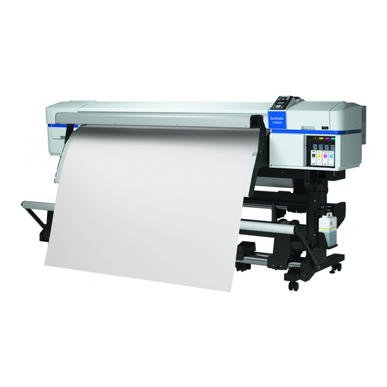
Revision B 1.1 Product Description Media handling Supports commercial media for solvent printers (no genuine media). SC-S30600 Series are a color Eco-Solvent ink jet printer that supports up to 64 inch Supported roll sizes are; wide paper. The main features are;... - Page 11 SC-S30600 Series Revision B Improvement of reliability/durability Head life: 1.5 year or 6,840 billion shots/1 line Operating life of the printer: 5 years or 67,500 m (64 inches/720x720 dpi/Bi- Figure 1-1. External View PRODUCT DESCRIPTION Product Description...
-
Page 12: Basic Specifications
SC-S30600 Series Revision B 1.2 Basic Specifications 1.2.2 Electric Specifications Printer Heater Additional Dryer 1.2.1 Basic Specifications Rated voltage 100 to 240 VAC 100 to 240 VAC 100 to 240 VAC Rated frequency 50 to 60 Hz 50 to 60 Hz... -
Page 13: Ink Specifications
SC-S30600 Series Revision B 1.2.3 Ink Specifications Item Specification Form Exclusive ink cartridge Pigment ink Black system: Black colors Color system: Yellow, Magenta, Cyan Cartridge life See the date printed on the package (at normal temperature) Guaranteed life... -
Page 14: Printing Specifications
SC-S30600 Series Revision B 1.3 Printing Specifications ROLL MEDIA SUPPLY EQUIPMENT Paper Core 1.3.1 Available Media Weight Roll Outer Diameter Diameter Normal Up to 40 kg Up to 250 mm 2 or 3 inch APPLICATION/TYPE Roll side: Up to 300 mm... - Page 15 SC-S30600 Series Revision B Paper board: Not supported PRINTABLE AREA Designated paper: Not supported Note *1: The value selected for Side Margin (Left) in the setup menu. The default value is 5mm. Choose a Side Margin (Left) over 10 mm when using media holding plates.
-
Page 16: Hardware Specifications
SC-S30600 Series Revision B 1.4 Hardware Specifications WEIGHT This section provides the printer dimensions and shows the main components. Item Weight Main body 146 kg 1.4.1 Dimensions and Weight Standard Roll Unit 19.5 kg Standard Reel Unit 21.5 kg DIMENSIONS... -
Page 17: Part Names
SC-S30600 Series Revision B 1.4.3 Part Names INSIDE FRONT SIDE Wiper Flushing Pad Media Holding Plate Platen Heater Cartridge Check Lamp After Heater Ink Cartridge Pressure Roller Lock Lever Front Cover Maintenance Cover (Right) Maintenance Cover (Left) Cutter Media Loading Lever... - Page 18 SC-S30600 Series Revision B BACK SIDE Drive Switch Pre Heater Handle Lift Lever Roll Holder Fixing Screw Roll Supporter Roll Holder Figure 1-7. Back Side PRODUCT DESCRIPTION Hardware Specifications Confidential...
-
Page 19: Control Panel
SC-S30600 Series Revision B 1.5 Control Panel Name Function 1 Power button Turns the printer ON or OFF. CONTROL PANEL ON: The power is ON. Flashing: The printer is receiving a data, turning the 2 Power light power OFF or processing head cleaning. - Page 20 SC-S30600 Series Revision B Name Function The setting number of the selected media, platen gap, media Display Description width and remaining amount of the media are indicated from the left. Icons of platen gap change according to the set value as follows.
- Page 21 SC-S30600 Series Revision B Name Function The setting of additional dryer is displayed. Drying fan functions. 6 Additional dryer status Drying fan does not function. PRODUCT DESCRIPTION Control Panel Confidential...
-
Page 22: Setup Menu
SC-S30600 Series Revision B 1.5.1 Setup Menu Menu Menu Item/Setting Values (shaded one is the default) Explanation Selects [On] to indicate and record the remaining amount of the set media, or [Off] to set it to off. When [On] is selected, [Length], [Remaining Alert] and Remaining Setup [Print Remaining Length] are displayed to be set. - Page 23 SC-S30600 Series Revision B Menu Menu Item/Setting Values (shaded one is the default) Explanation Printable Side Out Choose [Printable Side Out] or [Printable Side In] according to how the media Roll Type is rolled. Printable Side In Periodically Choose [Periodically] or [Every page] to have the printer automatically...
- Page 24 SC-S30600 Series Revision B Menu Menu Item/Setting Values (shaded one is the default) Explanation Auto (Uni-D) When granular images or blurring appear on the printed result, perform Gap Adjustment to adjust the Print Head misalignment during printing with this Auto (Bi-D) function.
- Page 25 SC-S30600 Series Revision B Menu Menu Item/Setting Values (shaded one is the default) Explanation Data Width Choose the range in which the print head moves during printing. [Data Width] restricts print head movement to the printed area. Restricting the extent of print head movement increases print speed.
- Page 26 SC-S30600 Series Revision B Menu Menu Item/Setting Values (shaded one is the default) Explanation Sets the side margin from the media’s right end while the media is set in the printer. The media’s right end differs depending on [Media End Check] setting in the Setup Menu as follows.
- Page 27 SC-S30600 Series Revision B Menu Menu Item/Setting Values (shaded one is the default) Explanation Selects the execution timing for Auto Nozzle Check from [Off] or once per [1] page to per [10] pages. When this is set to [Off], Auto Nozzle Check is not executed.
- Page 28 SC-S30600 Series Revision B Menu Menu Item/Setting Values (shaded one is the default) Explanation Turns to the sleep mode automatically when no error is occurring, no print job receiving or there are no operations on the control panel. In this setting, sets the time to turn to the sleep mode automatically.
- Page 29 SC-S30600 Series Revision B Menu Menu Item/Setting Values (shaded one is the default) Explanation Moves the Print Head to the maintenance position. Make sure to execute Head Maintenance Head Movement Move Head before washing the Wiper, Cap or Print Head. Moving the Print Head manually causes Print Head failure.
- Page 30 SC-S30600 Series Revision B Menu Menu Item/Setting Values (shaded one is the default) Explanation Sets the date and time for the internal clock. The set time is used for printing Date And Time MM/DD/YY HH:MM the job status and the printer status.
-
Page 31: Serviceman Mode
SC-S30600 Series Revision B 1.5.2 Serviceman Mode The Serviceman Mode is intended to be used by a service person for servicing the printer. HOW TO START & QUIT Turn the printer on by pressing the [Menu], [Back], and [OK] buttons together. - Page 32 SC-S30600 Series Revision B Menu Explanation Class Feed Amount 1 Feed Speed 1 Feed Amount 2 Feed Speed 2 Life Used only in manufacturing processes. Not used in service operations. Wait Life Count PGtyp PG++ Wait Life Count Display Count...
-
Page 33: Trouble Shooting
C H A P T E R TROUBLE SHOOTING Confidential... -
Page 34: Overview
SC-S30600 Series Revision B 2.1 Overview 2.1.1.2 Recurrence check of the trouble Check if the trouble the user claims recurs with the returned printer. This section explains the basic procedure for troubleshooting problems on the printer quickly and efficiently. -
Page 35: Troubleshooting Procedure
SC-S30600 Series Revision B 2.1.2 Troubleshooting Procedure 2.1.3.2 If necessary to escalate the trouble case Make a report with the following data. Refer to the following items according to the observed symptom, carry out the corresponding troubleshooting following the procedures described in the next sections. -
Page 36: Remedies For Maintenance Requests
SC-S30600 Series Revision B 2.2 Remedies for Maintenance Requests This section describes the remedies for maintenance requests. Maintenance requests do not effect the printer’s operation; therefore, you can continue the current printing. When a maintenance request error occurs, the printer displays on the LCD a hexadecimal code of “NNNN” which correspond to the bit numbers assigned to error statuses as shown in the table below. -
Page 37: Remedies For Service Call Error
SC-S30600 Series Revision B 2.3 Remedies for Service Call Error The following tables explains the Service Call error messages and remedies. Code Error Name Cause Check Item Remedy The Ink Tubes have reached the end of their service Replace the Ink Tubes... - Page 38 SC-S30600 Series Revision B Code Error Name Cause Check Item Remedy The CR Motor was driven at a speed faster than a predetermined one during deceleration. 1. Replace the CR Encoder. (Page 137) Irregular load CR Motor Does the CR Encoder work properly? Check it using 2.
- Page 39 SC-S30600 Series Revision B Code Error Name Cause Check Item Remedy Overcurrent to the PF Motor was detected. PF Encoder cable is damaged. 1. Replace the PF Encoder. (Page 162) PF Motor cable is damaged. Does the PF Encoder work properly? Check it using...
- Page 40 SC-S30600 Series Revision B Code Error Name Cause Check Item Remedy 1. Is the Pump Motor driver on the Main Board 1. Remove the foreign material. damaged? Pump Motor The control terminal (Vre terminal) of the Pump 1419 2. If the error still occurs, replace the Main Board.
- Page 41 SC-S30600 Series Revision B Code Error Name Cause Check Item Remedy The Pump Cap Unit has reached the end of its service Suction pump Replace the Pump Cap Unit (Page 141) and reset the 1431 life. (The total number of revolutions of the Pump...
- Page 42 SC-S30600 Series Revision B Code Error Name Cause Check Item Remedy Abnormally-long driving duration of the APG Motor was detected. APG Motor 151D Replace the Main Board. (Page 107) driving time-out error Irregular load Firmware becomes out of control.
- Page 43 SC-S30600 Series Revision B Code Error Name Cause Check Item Remedy Abnormally-long driving duration of the ATC Motor was detected. ATC Motor 159D Replace the Main Board. (Page 107) driving time-out error Irregular load Firmware becomes out of control.
- Page 44 SC-S30600 Series Revision B Code Error Name Cause Check Item Remedy There is a problem with a specific bit on the board, Replace the Sub-F Board of the Reel Unit. (Page 1617 Reel Unit Board failure Unexpected error which detects what device is connected to the board.
- Page 45 SC-S30600 Series Revision B Code Error Name Cause Check Item Remedy 1. Replace the IC Holder. (Page 143) 1F80 CSIC error CSIC control error 2. Replace the Main Board. (Page 107) 1. Replace the IC Holder. (Page 143) 1F81 CSIC error CSIC control error 2.
- Page 46 SC-S30600 Series Revision B Code Error Name Cause Check Item Remedy 1. Re-install the firmware. (Page 227) There is something wrong with the firmware. Fxxx CPU related service call Is the firmware installed correct one for the printer? ...
- Page 47 SC-S30600 Series Revision B Code Error Name Cause Check Item Remedy Connection failure of the Reel Motor. 1. Is there any problems such as damaged cable in the The Reel Motor was driven at a speed abnormally connections below? slower than a predetermined one during operation.
- Page 48 SC-S30600 Series Revision B Code Error Name Cause Check Item Remedy 1. Is the cable connected properly? 1. Reconnect the cable. Pre Heater 2. Is the Sub-E Board out of order? 2. Replace the cable. Cable disconnection, breaking, blowout of a fuse, or...
-
Page 49: Remedies For Print Quality Troubles
SC-S30600 Series Revision B 2.4 Remedies for Print Quality Troubles This section provides troubleshooting of print quality troubles classifying them by observed symptom. Before performing troubleshooting, refer to and print “Nozzle Check” (p248) nozzle check pattern. Examine the printed pattern, and if any missing segment is found, perform the Print Head cleaning. - Page 50 SC-S30600 Series Revision B Table 2-2. Print Quality Troubles Symptom Cause Check Item Remedy Carry out the following adjustments. CR Direction Head Slant Adjustment (Page The Print Head has not been adjusted 251) properly. PF Direction Head Slant Adjustment...
- Page 51 SC-S30600 Series Revision B Table 2-2. Print Quality Troubles Symptom Cause Check Item Remedy Carry out the following adjustments. Adjustment failure of the IM Sensor Auto Bi-D Adjustment (Page 242) IM Sensor Check & Adjustment (Page 238) Carry out the adjustments correctly.
- Page 52 SC-S30600 Series Revision B Table 2-2. Print Quality Troubles Symptom Cause Check Item Remedy 1. Is the paper wrinkled, bent, rippled, or warped? 1. Replace the paper with a proper new one. There is a problem with the paper used.
-
Page 53: Trouble On Paper Feeding
SC-S30600 Series Revision B 2.5 Trouble on Paper Feeding This section describes the possible troubles on paper feeding and their causes and remedies. Table 2-3. Trouble on Paper Feeding Symptom Cause Check Item Remedy Improper PE Sensor adjustment Perform the Rear AD Adjustment. - Page 54 SC-S30600 Series Revision B Table 2-3. Trouble on Paper Feeding Symptom Cause Check Item Remedy Paper feed amount is not configured Perform the Feed Adjustment. (Page 263) correctly. Enable (select “ON”) the Media Size Check The Media Size Check function has function.
- Page 55 SC-S30600 Series Revision B How to correct the distortion HOW TO CHECK AND CORRECT TENSIONER DISTORTION Loosen the screw that secures the weight of the tensioner. (This step is needed How to check the distortion because the screw is in contact with the screws to be loosened at the next step.)
- Page 56 SC-S30600 Series Revision B Gently press the tensioner against the printer, and press the left and right stoppers against the cases. While pressing the stoppers against the cases, temporarily tighten the screws that were loosened at step 2. Using a torque screwdriver and at 1.96N, securely tighten the screws in the order shown below.
-
Page 57: Other Troubles
SC-S30600 Series Revision B 2.6 Other Troubles Table 2-4. Other Troubles Symptom Cause Check Item Remedy The power cable is unplugged Is the power plug connected properly? Connect it properly. Is the electrical outlet overloaded sharing with any other Use one electrical outlet for the printer only if The power voltage is unstable. - Page 58 SC-S30600 Series Revision B Table 2-4. Other Troubles Symptom Cause Check Item Remedy The power cable of the After Heater is After Heater power failure occurs Connect the power cable of the After Heater. not connected. 1. Is the heater setting appropriate in the ambient 1.
-
Page 59: Trouble On Service Program
SC-S30600 Series Revision B 2.7 Trouble on Service Program This section describes possible troubles on Service Program and their causes and remedies. Table 2-5. Troubles on Service Program Symptom Cause Check Item Remedy Are you running the program on the following operating... -
Page 60: Trouble On Nvram Viewer
SC-S30600 Series Revision B 2.8 Trouble on NVRAM Viewer This section describes possible troubles on NVRAM Viewer and their causes and remedies. Table 2-6. Trouble on NVRAM Viewer Symptom Cause Check Item Remedy With a text editor, open the ini file (ServPrg.ini) in the... - Page 61 C H A P T E R DISASSEMBLY & ASSEMBLY Confidential...
-
Page 62: Overview
SC-S30600 Series Revision B 3.1 Overview 3.1.1 Precautions Before starting the disassembly or reassembly of the product, read the following This chapter describes procedures for disassembling the main components of SC- precautions given under the headings “WARNING” and “CAUTION”. S30600 Series. - Page 63 SC-S30600 Series Revision B The power switch for this printer is installed on the secondary Locate the printer on a stable and flat surface. W A R N I N G C A U T I O N ...
-
Page 64: Cautions After Assembling
SC-S30600 Series Revision B 3.1.2 Cautions After Assembling 3.1.3 Orientation Definition The terms used for indicating the orientation/direction throughout this chapter are as The ink-path-related components or parts should be firmly and C A U T I O N follows. -
Page 65: Recommended Tools
SC-S30600 Series Revision B 3.1.4 Recommended Tools To protect this product from damage, use the tools indicated in the following table. For the tools required to perform the adjustment, refer to “Tools/Consumables for Adjustments” in Chapter 4. Table 3-1. Tools... -
Page 66: Parts Diagram
SC-S30600 Series Revision B 3.2 Parts Diagram Left Rear Cover (p. 94) Left Upper Cover (p. 95) Upper Cover (p. 100) Left Cover (p. 98) Panel Unit (p. 86) Left Lower Cover (p. 99) ... - Page 67 SC-S30600 Series Revision B Front Cover L Sensor (p. 106) Detects the Open/Closed status of the Front Cover. Front Cover R Sensor (p. 104) Detects the Open/Closed status of the Front Cover. R Maintenance Cover Sensor (p. 102) Detects the Open/Closed status of the Right Maintenance Cover.
- Page 68 SC-S30600 Series Revision B Sub-D Board (p. 114) Relays the connection between the Main Board and the Print Head. Sub-E Board (p. 115) Controls heaters. Sub Board (p. 113) Relays the connection between the Main Board and electric parts/components.
- Page 69 SC-S30600 Series Revision B PW Sensor (p. 155) Detects the width of paper on the platen. This is a Damper Kit (p. 120) reflective photo interrupter and detects the difference of the amount of reflection between paper (white) and the platen (black).
- Page 70 SC-S30600 Series Revision B Wiper (p. 84) Cleans the nozzle surface of the Print Head. Wiper Cleaner (p. 84) Ink Tube (p. 147) Wipes off ink attached on the Wiper. Flushing Pad (p. 85) Pump Cap Unit (p. 141)
- Page 71 SC-S30600 Series Revision B Media Loading Lever (p. 158) Media Loading Lever Sensor (p. 159) Detects the position of the Media Loading Lever. Driven Roller Assy (p. 165) PF Motor (p. 161) The motor to drive the Feed Roller.
- Page 72 SC-S30600 Series Revision B Pre Heater (p. 171) Heats paper before printing. This pre-heating combined with the heating on the Platen Heaters and the After Heaters allows raising the paper temperature successfully after the paper feeding starts. The pre-heating also prevents the paper from deforming when heating during printing operation.
- Page 73 SC-S30600 Series Revision B Roll Paper Holder (p. 178) Roll Receiver Assy (p. 177) Roll Unit (p. 176) Sub-F Board (Roll) (p. 179) ATC Motor (p. 181) Relays the connection between the Main Board and the Roll Feeds forward (normal rotation) and rewinds (reverse Unit.
- Page 74 SC-S30600 Series Revision B Reel Motor (p. 188) Rewinds the media. Roll Paper Holder (p. 185) Tension Bar Upper Sensor / Tension Bar Lower Sensor (p. 191) Reel Unit (p. 184) Detects the position of the Tension Bar to control the rewinding operation of the Reel Motor.
- Page 75 SC-S30600 Series Revision B Drying Fan Cover (p. 194) Drying Fan Power Supply Board (p. 196) Generates the DC voltage for the Drying Fan Unit from the AC power supply. Sub-I Board (p. 195) Relays the connection between the Main Board and the Drying Fan Unit.
-
Page 76: Disassembly Flowchart
SC-S30600 Series Revision B 3.3 Disassembly Flowchart CONSUMABLES/ACCESSORIES Start “3.4.1.1 Unlocking the CR Unit” “3.4.2.3 Flushing Pad” (p85) “3.4.2.1 Wiper” (p84) “3.4.2.2 Wiper Cleaner” (p84) (p82) HOUSING Start “3.4.6.1 Media Loading Lever” “3.4.3.12 Board Box Cover” (p101) “3.4.3.1 Panel Unit” (p86) “3.4.3.6 Left Rear Cover”... - Page 77 SC-S30600 Series Revision B ELECTRIC CIRCUIT COMPONENTS Start “3.4.6.1 Media Loading Lever” “3.4.1.1 Unlocking the CR Unit” “3.4.7.3 After Heater” (p174) “3.4.3.12 Board Box Cover” (p101) (p158) (p82) “3.4.3.2 Right Upper Cover” (p88) “3.4.4.3 Power Supply Board” “3.4.3.1 Panel Unit” (p86) “3.4.4.6 Sub-E Board”...
-
Page 78: Carriage Mechanism
SC-S30600 Series Revision B CARRIAGE MECHANISM Start “3.4.6.1 Media Loading Lever” “3.4.1.1 Unlocking the CR Unit” (p158) (p82) “3.4.6.1 Media Loading Lever” “3.4.6.1 Media Loading Lever” “3.4.3.2 Right Upper Cover” (p88) “3.4.3.1 Panel Unit” (p86) “3.4.2.2 Wiper Cleaner” (p84) “3.4.3.6 Left Rear Cover” (p94) “3.4.5.7 CR Scale”... - Page 79 SC-S30600 Series Revision B INK SYSTEM MECHANISM Start “3.4.6.1 Media Loading Lever” “3.4.1.1 Unlocking the CR Unit” (p158) (p82) “3.4.6.1 Media Loading Lever” “3.4.3.1 Panel Unit” (p86) (p158) “3.4.3.2 Right Upper Cover” (p88) “3.4.3.1 Panel Unit” (p86) “3.4.3.2 Right Upper Cover” (p88) “3.4.3.3 Right Front Cover”...
- Page 80 SC-S30600 Series Revision B PAPER FEED MECHANISM Start “3.4.6.1 Media Loading Lever” “3.4.6.2 Media Loading Lever “3.4.6.7 Driven Roller Assy” “3.4.3.6 Left Rear Cover” (p94) “3.4.7.3 After Heater” (p174) “3.4.7.1 Pre Heater” (p171) (p158) Sensor” (p159) (p165) “3.4.6.9 PE Sensor” (p170) “3.4.3.7 Left Upper Cover”...
- Page 81 SC-S30600 Series Revision B ROLL UNIT Start “3.4.8.1 Roll Unit” (p176) “3.4.8.2 Roll Receiver Assy” (p177) “3.4.8.3 Roll Paper Holder” (p178) “3.4.8.4 Sub-F Board (Roll)” “3.4.8.5 ATC Motor” (p181) (p179) REEL UNIT Start “3.4.9.5 Tension Bar Upper Sensor / “3.4.9.1 Reel Unit” (p184) “3.4.9.2 Roll Paper Holder”...
-
Page 82: Disassembly And Assembly Procedure
SC-S30600 Series Revision B 3.4 Disassembly and Assembly Procedure This section describes procedures for disassembling the components allowed to be disassembled. Unless otherwise specified, disassembled units or components can be reassembled by reversing the disassembly procedure. 3.4.1 Preparation for Servicing 3.4.1.1 Unlocking the CR Unit... - Page 83 SC-S30600 Series Revision B Manual C A U T I O N - Right side - No clock rotation! Remove the Right Maintenance Cover. Remove the screw, and remove the cover. A) Silver M3x8 P-tite screw with built-in washer: 1 pcs Insert a screwdriver into the cover through the hole as shown in the figure.
-
Page 84: Consumables/Accessories
SC-S30600 Series Revision B 3.4.2 Consumables/Accessories 3.4.2.2 Wiper Cleaner Turn the printer on. 3.4.2.1 Wiper Press the [Menu] button, select Head Maintenance, and press the [OK] button. Turn the printer on. The CR Unit moves to the left end. Press the [Menu] button, select Head Maintenance, and press the [OK] button. - Page 85 SC-S30600 Series Revision B 3.4.2.3 Flushing Pad Turn the printer on. Press the [Menu] button, select Head Maintenance, and press the [OK] button. The CR Unit moves to the left end. Open the Right Maintenance Cover. Pull up the handle, and remove the Flushing Pad in the direction of the arrow.
-
Page 86: Housing
SC-S30600 Series Revision B 3.4.3 Housing Right Maintenance Cover 3.4.3.1 Panel Unit Right Upper Cover Tabs Open the Right Maintenance Cover. Open the Front Cover. Remove the four screws that secure the Panel Unit. Panel Unit Assy A) Silver M4x10 P-tite screw with washer: 2 pcs B) Silver M4x12 P-tite screw with washer: 2 pcs Pull the left lower portion of the Panel Unit Assy toward you and remove it. - Page 87 SC-S30600 Series Revision B Disconnect the FFC from the connector of the Panel Board. Disengage the two hooks and separate the Panel Unit from the Panel Unit Assy. Connector Panel Unit Panel Unit Figure 3-18. Disassembled Panel Unit Hooks Figure 3-17. Removing the Panel Unit DISASSEMBLY &...
- Page 88 SC-S30600 Series Revision B 3.4.3.2 Right Upper Cover Remove the four screws, and remove the Board Right Frame. A) Silver M3x6 screw: 4 pcs Remove the Media Loading Lever. (p158) Remove the Panel Unit. (p86) - Right side - Push the Media Loading Lever Frame toward the rear of the printer to move the lever to its release position.
- Page 89 SC-S30600 Series Revision B Remove the seven screws that secure the Board Box, and slide the Board Box in - Right rear side - the direction of the arrow. B) Silver M4x10 screw with washer: 6 pcs C) Silver M3x6 screw: 1 pcs...
- Page 90 SC-S30600 Series Revision B Remove the five screws that secure the Right Upper Cover. - Right rear side - Right Upper Cover D) Silver M4x12 P-tite screw with washer: 1 pcs E) Silver M3x10 P-tite screw with washer: 1 pcs...
- Page 91 SC-S30600 Series Revision B 3.4.3.3 Right Front Cover Remove the Media Loading Lever. (p158) - Right side - Remove the Panel Unit. (p86) Positioning hole and dowel Remove the Right Upper Cover. (p88) Remove the screw, and remove the R Maintenance Cover Sensor.
- Page 92 SC-S30600 Series Revision B 3.4.3.4 Right Cover - Right side - Remove the Media Loading Lever. (p158) Right Cover Right Front Cover Remove the Panel Unit. (p86) Remove the Right Upper Cover. (p88) Remove the three screws, and remove the Right Cover.
- Page 93 SC-S30600 Series Revision B 3.4.3.5 Right Lower Cover - Right side - Remove the Media Loading Lever. (p158) Remove the Panel Unit. (p86) Remove the Right Upper Cover. (p88) Remove the Right Cover. (p92) Remove the three screws, and remove the Right Lower Cover sliding it toward the rear of the printer.
- Page 94 SC-S30600 Series Revision B 3.4.3.6 Left Rear Cover - Left rear side - Left Upper Cover Remove the screw, and remove the Left Rear Cover in the direction of the arrow. A) Silver M4x10 S-tite screw with washer: 1 pcs Insert the four tabs of the Left Rear Cover into the four positioning holes on the Left Upper Cover.
- Page 95 SC-S30600 Series Revision B 3.4.3.7 Left Upper Cover Open the Front Cover. Open the Left Maintenance Cover. Remove the Left Rear Cover. (p94) Remove the four screws that secure the Left Upper Cover. Loosen the three screws (A) of the Left Rear Lower Cover.
- Page 96 SC-S30600 Series Revision B Holding the Front Cover upright, remove the Left Upper Cover pulling out its joint part in the direction of the arrow. Front Cover Joint part Left Upper Cover Figure 3-31. Removing the Left Upper Cover DISASSEMBLY & ASSEMBLY...
- Page 97 SC-S30600 Series Revision B 3.4.3.8 Left Front Cover/L Maintenance Cover Sensor Remove the six screws that secure the Left Front Cover. B) Silver M4x10 S-tite screw with washer: 5 pcs Remove the Left Rear Cover. (p94) C) Silver M4x12 P-tite screw with washer: 1 pcs Remove the Left Upper Cover.
- Page 98 SC-S30600 Series Revision B 3.4.3.9 Left Cover Left Cover - Left side - Remove the Left Rear Cover. (p94) Remove the Left Upper Cover. (p95) Remove the three screws and slide the Left Cover toward the rear to remove it.
- Page 99 SC-S30600 Series Revision B 3.4.3.10 Left Lower Cover - Left side - Remove the Left Rear Cover. (p94) Remove the Left Upper Cover. (p95) Remove the Left Cover. (p98) Remove the two screws, and remove the Left Lower Cover sliding it toward the rear of the printer.
- Page 100 SC-S30600 Series Revision B 3.4.3.11 Upper Cover - Rear side - Remove the Media Loading Lever. (p158) Remove the Panel Unit. (p86) Remove the Right Upper Cover. (p88) Remove the Left Rear Cover. (p94) Remove the Left Upper Cover. (p95) Remove the 13 screws, and remove the Upper Cover.
- Page 101 SC-S30600 Series Revision B 3.4.3.12 Board Box Cover - Right rear side - Remove the nine screws that secure the Board Box Cover. A) Silver M3x6 screw: 9 pcs Lift the Board Box Cover to remove it. Board Box Cover Figure 3-37.
- Page 102 SC-S30600 Series Revision B 3.4.3.13 R Maintenance Cover Sensor Remove the Media Loading Lever. (p158) - Right upper side - FFC Clamp R Maintenance Cover Sensor Cable Remove the Panel Unit. (p86) Remove the Right Upper Cover. (p88) FFC Clamps Remove the Board Box Cover.
- Page 103 SC-S30600 Series Revision B Remove the screw that secures the R Maintenance Cover Sensor. - Right front side - A) Silver M3x8 P-tite screw with built-in washer: 1 pcs Pull out the cable through the three holes on the frame.
- Page 104 SC-S30600 Series Revision B 3.4.3.14 Front Cover R Sensor Remove the Media Loading Lever. (p158) - Right upper side - FFC Clamp Front Cover R Sensor Cable Remove the Panel Unit. (p86) Remove the Right Upper Cover. (p88) FFC Clamps Remove the Board Box Cover.
- Page 105 SC-S30600 Series Revision B Remove the screw that secures the mounting plate. A) Silver M3x8 S-tite screw with built-in washer: 1 pcs Lift the mounting plate to disengage the hook and remove the Front Cover R Sensor together with the mounting plate.
- Page 106 SC-S30600 Series Revision B 3.4.3.15 Front Cover L Sensor Remove the two screws that secure the Front Cover L Sensor. A) Silver M3x8 P-tite screw with washer: 2 pcs Remove the Left Rear Cover. (p94) Pull out the cable through the hole on the frame, and remove the Front Cover L Remove the Left Upper Cover.
-
Page 107: Electric Circuit Components
SC-S30600 Series Revision B 3.4.4 Electric Circuit Components Disconnect all cables and FFCs from the Main Board. Remove the eight screws, and remove the Main Board. 3.4.4.1 Main Board B) Silver M3x6 screw: 7 pcs When replacing/removing this part, refer to “4.1.2 Adjustment... - Page 108 SC-S30600 Series Revision B 3.4.4.2 Main-B Board - Right rear side - When replacing/removing this part, refer to “4.1.2 Adjustment A D J U S T M E N T R E Q U I R E D Items and the Order by Repaired Part” (p200)
- Page 109 SC-S30600 Series Revision B 3.4.4.3 Power Supply Board When replacing/removing this part, refer to “4.1.2 Adjustment Clams A D J U S T M E N T R E Q U I R E D Items and the Order by Repaired Part” (p200) and make sure to perform the specified operations including required adjustment.
- Page 110 SC-S30600 Series Revision B Disconnect the connector of the Reel Unit. Disconnect and release the cables from two relay connectors and from the two clamps. Remove the five screws, and remove the Right Rear Cover. B) Silver M4x10 S-tite screw with washer: 4 pcs...
- Page 111 SC-S30600 Series Revision B Remove the five screws that secure the Power Supply Board Box. 11. Release the cables from the three clamps of the Power Supply Board Box Cover. D) Silver M4x10 S-tite screw with washer: 2 pcs 12. Remove the five screws, and remove the Power Supply Board Box Cover.
- Page 112 SC-S30600 Series Revision B 13. Disconnect the cables from the connectors (CN1, CN2) on the Power Supply Board. 14. Remove the nine screws, and remove the Power Supply Board. G) Silver M3x6 screw: 9 pcs Power Supply Board Figure 3-53. Removing the Power Supply Board DISASSEMBLY &...
- Page 113 SC-S30600 Series Revision B 3.4.4.4 Sub Board - Upper side of the CR Unit - Unlock the CR Unit. (p82) Remove the Left Rear Cover. (p94) Remove the Left Upper Cover. (p95) Sub Board Remove the CR Cover. (p119) Disconnect all cables and FFCs from the Sub Board.
- Page 114 SC-S30600 Series Revision B 3.4.4.5 Sub-D Board Disconnect all FFCs from the Sub-D Board. Remove the four screws, and remove the Sub-D Board. Remove the Media Loading Lever. (p158) A) Silver M3x8 S-tite screw: 4 pcs Remove the Panel Unit.
- Page 115 SC-S30600 Series Revision B 3.4.4.6 Sub-E Board Disconnect all cables from the Sub-E Board. Remove the seven screws, and remove the Sub-E Board. Remove the After Heater. (p174) B) Silver M3x8 S-tite screw: 7 pcs Remove the three screws, and remove the Sub-E Board Cover.
- Page 116 SC-S30600 Series Revision B 3.4.4.7 Sub-M Board Disconnect all cables connected to the Sub-M Board. Remove the four screws, and remove the Sub-M Board. Remove the Media Loading Lever. (p158) B) Silver M3x6 screw: 4 pcs Remove the Right Upper Cover.
- Page 117 SC-S30600 Series Revision B 3.4.4.8 Box Cooling Fan Remove the sponge that secures the FFC. When replacing the Box Cooling Fan, make sure to also replace the C H E C K When attaching the sponge, route the CR FFC and the Head Relay P O I N T duct.
- Page 118 SC-S30600 Series Revision B Insert a screwdriver into the duct to remove the two screws, and remove the Box The duct provided as an ASP needs to be built as shown before Cooling Fan. installing it to the printer.
-
Page 119: Carriage Mechanism/Ink System Mechanism
SC-S30600 Series Revision B 3.4.5 Carriage Mechanism/Ink System Mechanism Release the portion of the CR Cover engaged with the CR Unit from the unit, disengage the two tabs and remove the CR Cover. 3.4.5.1 CR Cover Unlock the CR Unit. - Page 120 SC-S30600 Series Revision B 3.4.5.2 Damper Kit Joint Rubbers When replacing/removing this part, refer to “4.1.2 Adjustment A D J U S T M E N T Ink Path Joint R E Q U I R E D Items and the Order by Repaired Part” (p200) and make sure to perform the specified operations including required adjustment.
- Page 121 SC-S30600 Series Revision B 3.4.5.3 Print Head Clamp When replacing/removing this part, refer to “4.1.2 Adjustment A D J U S T M E N T R E Q U I R E D Items and the Order by Repaired Part” (p200) and make sure to perform the specified operations including required adjustment.
- Page 122 SC-S30600 Series Revision B 10. Remove the FFC clamp. FFC clamp Head FFCs 11. Remove the three screws, and remove the Print Head. C) Silver M3x8 screw (Bit No.1): 3 pcs 12. Disconnect the Head FFCs from the Print Head.
- Page 123 SC-S30600 Series Revision B 3.4.5.4 Head FFC 11. Disengage the two hooks, and remove the FFC Holder. Remove the Media Loading Lever. (p158) - Rear side of the CR Unit- Remove the Panel Unit. (p86) Remove the Right Upper Cover.
- Page 124 SC-S30600 Series Revision B 13. Release the Head FFC from the FFC Holders. 14. Remove the pieces of acetate tape, and release the Head FFC from the two FFC clamps. 15. Remove the pieces of acetate tape, and release the cover from the two hooks of the FFC Holders frame.
- Page 125 SC-S30600 Series Revision B When routing the Head FFC through the Ink Path Holder Assy, make sure to let the FFC run under the hooks as shown below. - Rear side - Hook - Front side - Lap the FFCs and then fold them.
- Page 126 SC-S30600 Series Revision B 3.4.5.5 Head Relay FFC 11. Disconnect the Head Relay FFCs from the connectors (CN400, CN401) on the Main Board. Remove the Media Loading Lever. (p158) 12. Pull out the Head Relay FFCs from the main body.
- Page 127 SC-S30600 Series Revision B When attaching the Head Relay FFCs, make sure to let them through the FFC Holder. Lap the FFCs and then fold them together. CN400 CN401 DISASSEMBLY & ASSEMBLY Disassembly and Assembly Procedure Confidential...
- Page 128 SC-S30600 Series Revision B 3.4.5.6 CR FFC 14. Release the CR FFC from the FFC Holders. Remove the Media Loading Lever. (p158) CR FFC Remove the Panel Unit. (p86) Remove the Right Upper Cover. (p88) Remove the Left Rear Cover.
- Page 129 SC-S30600 Series Revision B 15. Disconnect the CR FFC from the connector (CN100) on the Main Board. 16. Pull out the CR FFC from the main body. FFC Holder When attaching the CR FFC, make sure to let it through the FFC Holders.
- Page 130 SC-S30600 Series Revision B 3.4.5.7 CR Scale - Right side - - Left side - Left Side When replacing/removing this part, refer to “4.1.2 Adjustment CR Scale A D J U S T M E N T R E Q U I R E D Items and the Order by Repaired Part”...
- Page 131 SC-S30600 Series Revision B Make sure to attach the CR Scale to the CR Scale Holder as shown. CR Scale Holder Rouge the scale behind these portions CR Scale Make sure the CR Scale can run through the slit of the CR Encoder.
- Page 132 SC-S30600 Series Revision B 3.4.5.8 CR Timing Belt Pulley Shaft Pulley Cover When replacing/removing this part, refer to “4.1.2 Adjustment A D J U S T M E N T R E Q U I R E D Items and the Order by Repaired Part” (p200)
- Page 133 SC-S30600 Series Revision B 18. Remove the CR Timing Belt from the belt holder on the back side of the CR Unit. - Back side of the CR Unit - Belt Holder Attach the CR Timing Belt to the CR Unit so that the joint clips on the belt locate within the range shown below.
- Page 134 SC-S30600 Series Revision B 3.4.5.9 CR Motor - Left side - When replacing/removing this part, refer to “4.1.2 Adjustment A D J U S T M E N T R E Q U I R E D Items and the Order by Repaired Part” (p200) and make sure to perform the specified operations including required adjustment.
- Page 135 SC-S30600 Series Revision B 10. Move the CR Unit until to a position over the platen. 11. Remove the CR Timing Belt from the pinion gear of the CR Motor. 12. Disconnect the CR Motor Cable from the connector (CN1) on the Sub-M Board, and release the CR Motor Cable from the clamp.
- Page 136 SC-S30600 Series Revision B 3.4.5.10 CR HP Sensor - Rear side - Unlock the CR Unit. (p82) Remove the Media Loading Lever. (p158) Remove the Right Upper Cover. (p88) CR HP Sensor Move the CR Unit until to a position over the platen.
- Page 137 SC-S30600 Series Revision B 3.4.5.11 CR Encoder - Back Side of the CR Unit - When replacing/removing this part, refer to “4.1.2 Adjustment A D J U S T M E N T R E Q U I R E D Items and the Order by Repaired Part”...
- Page 138 SC-S30600 Series Revision B 3.4.5.12 APG Motor - Right side - When replacing/removing this part, refer to “4.1.2 Adjustment A D J U S T M E N T APG Unit R E Q U I R E D Items and the Order by Repaired Part” (p200) and make sure to perform the specified operations including required adjustment.
- Page 139 SC-S30600 Series Revision B Disconnect the cable from the connector of the APG Motor, and remove the APG Remove the two screws, and remove the APG Motor. Unit. B) Silver M2x4 (Bit No.1): 2 pcs Be careful not to damage the encoder and scale of the APG Motor.
- Page 140 SC-S30600 Series Revision B 3.4.5.13 PG HP Sensor Unlock the CR Unit. (p82) - Back Side of the CR Unit - Remove the Wiper Cleaner. (p84) Incline plate Remove the Media Loading Lever. (p158) PG HP Sensor Remove the Right Upper Cover.
- Page 141 SC-S30600 Series Revision B 3.4.5.14 Pump Cap Unit When replacing/removing this part, refer to “4.1.2 Adjustment A D J U S T M E N T Cable Cover R E Q U I R E D Items and the Order by Repaired Part” (p200) and make sure to perform the specified operations including required adjustment.
- Page 142 SC-S30600 Series Revision B 10. Remove the three screws that secure the Pump Cap Unit. B) Silver M4x8 S-tite screw with built-in washer: 3 pcs 11. Remove the two Waste Ink Tubes from the joint, and release the tubes from the clamp.
- Page 143 SC-S30600 Series Revision B 3.4.5.15 IC Holder Clamp When replacing/removing this part, refer to “4.1.2 Adjustment A D J U S T M E N T R E Q U I R E D Items and the Order by Repaired Part” (p200) and make sure to perform the specified operations including required adjustment.
- Page 144 SC-S30600 Series Revision B 12. Disconnect the cable of the Reel Unit. 14. Remove the screw that secures the joint. 13. Remove the five screws, and remove the Right Rear Cover. C) Silver M3x6 screw with built-in washer: 1 pcs A) Silver M4x10 S-tite screw with washer: 4 pcs ...
- Page 145 SC-S30600 Series Revision B 16. Disconnect the FFC from the rear of the IC Holder. - Rear side of Holder- 17. Remove the four screws that secure the IC Holder. E) Silver M4x10 S-tite screw with built-in washer: 4 pcs...
- Page 146 SC-S30600 Series Revision B When installing the joint, confirm the following. Before installing the joint, make sure the two Joint Rubbers are attached to it. Before attaching the Joint Rubbers, let them get wet with cleaning liquid. Joint Rubbers ...
- Page 147 SC-S30600 Series Revision B 3.4.5.16 Ink Tube When replacing/removing this part, refer to “4.1.2 Adjustment A D J U S T M E N T Ink Tube Holder R E Q U I R E D Ink Tubes Path Items and the Order by Repaired Part” (p200) and make sure to perform the specified operations including required adjustment.
- Page 148 SC-S30600 Series Revision B Ink Tube Holder Ink Tube Joint Figure 3-102. Removing the Ink Tubes Figure 3-101. Ink Tube Holder When installing the Ink Tubes, confirm that there is no torsion When the joint is removed in the next step, ink may drip off from of the Ink Tubes.
- Page 149 SC-S30600 Series Revision B 3.4.5.17 Flushing Box Unlock the CR Unit. (p82) Remove the Media Loading Lever. (p158) Flushing Box Remove the Panel Unit. (p86) Remove the Right Upper Cover. (p88) Remove the Right Front Cover. (p91) Waste Ink Tubes Move the CR Unit to a position over the platen.
- Page 150 SC-S30600 Series Revision B Open the two clamps and release the Waste Ink Tubes. After pulling out the Waste Ink Tube, put waste cloth or the like C A U T I O N into the tip of the tube to prevent ink from dripping from the tube.
- Page 151 SC-S30600 Series Revision B 3.4.5.18 CR Unit When replacing/removing this part, refer to “4.1.2 Adjustment A D J U S T M E N T R E Q U I R E D Items and the Order by Repaired Part” (p200)
- Page 152 SC-S30600 Series Revision B 16. Disconnect the CR FFC from the connector (CN100) on the Sub Board. 19. Remove the three screws, and remove the CR Stopper. 17. Remove the FFC clamp that secures the Head FFCs. D) Silver M3x8 screw: 3 pcs 20.
- Page 153 SC-S30600 Series Revision B Before performing the next step, check that the Wiper is at its When replacing the CR Unit, remove the CR Slider following the C A U T I O N Lubrication Lubrication standby position. procedure below and lubricate it. For instructions on the lubrication, see “5.6 Lubrication”...
- Page 154 SC-S30600 Series Revision B 3.4.5.19 Oil Pad Holder The procedure below is for disassembling the Oil Pad Holder at the C H E C K P O I N T right. Use the same procedure for disassembling the left one.
- Page 155 SC-S30600 Series Revision B 3.4.5.20 PW Sensor - Left Side of the CR Unit - When replacing/removing this part, refer to “4.1.2 Adjustment A D J U S T M E N T R E Q U I R E D Items and the Order by Repaired Part”...
- Page 156 SC-S30600 Series Revision B Disconnect the FFC from the PW Sensor, and remove the PW Sensor. - Bottom of the CR Unit - PW Sensor Figure 3-112. Removing the PW Sensor Position the PW Sensor so that its sensing portion and connector are located as shown.
- Page 157 SC-S30600 Series Revision B 3.4.5.21 IM Sensor Before installing the IM Sensor to the CR Unit, insert its protruded portion into the groove of the Sensor Cover. When replacing/removing this part, refer to “4.1.2 Adjustment A D J U S T M E N T R E Q U I R E D Items and the Order by Repaired Part”...
-
Page 158: Paper Feed Mechanism
SC-S30600 Series Revision B 3.4.6 Paper Feed Mechanism 3.4.6.1 Media Loading Lever Move the Media Loading Lever to the front side, and set it to the “Hold” position. Media Loading Lever Remove the two screws, and remove the Media Loading Lever. - Page 159 SC-S30600 Series Revision B 3.4.6.2 Media Loading Lever Sensor Remove the six screws that secure the Rear Cover. C) Silver M3x8 S-tite screw with built-in washer: 6 pcs Move the Media Loading Lever to the rear side, and set it to the release position.
- Page 160 SC-S30600 Series Revision B Remove the two screws, and remove the cover. D) Silver M3x8 S-tite screw with built-in washer: 2 pcs Cover Figure 3-118. Removing the Cover Disengage the hook, and remove the Media Loading Lever Sensor. Media Loading Lever Sensor Figure 3-119.
- Page 161 SC-S30600 Series Revision B 3.4.6.3 PF Motor Loosen the two screws (A) that secure the PF Motor Mounting Plate. When replacing/removing this part, refer to “4.1.2 Adjustment A D J U S T M E N T Before tightening the screw A, move the PF Motor Mounting Plate R E Q U I R E D Items and the Order by Repaired Part”...
- Page 162 SC-S30600 Series Revision B 3.4.6.4 PF Encoder Remove the Left Rear Cover. (p94) Remove the Left Upper Cover. (p95) Remove the Left Cover. (p98) Disconnect the FFC from the connector of the PF Encoder. Remove the screw, and remove the PF Encoder.
- Page 163 SC-S30600 Series Revision B 3.4.6.5 PF Scale When replacing/removing this part, refer to “4.1.2 Adjustment A D J U S T M E N T PF Scale R E Q U I R E D Items and the Order by Repaired Part” (p200) and make sure to perform the specified operations including required adjustment.
- Page 164 SC-S30600 Series Revision B 3.4.6.6 PF Timing Belt Tension Spring When replacing/removing this part, refer to “4.1.2 Adjustment A D J U S T M E N T R E Q U I R E D Items and the Order by Repaired Part” (p200)
- Page 165 SC-S30600 Series Revision B 3.4.6.7 Driven Roller Assy Do not scratch the PF Roller with the shaft of the Driven Roller C A U T I O N Driven Roller Holder Assy. Driven Roller Assy Do not touch the Driven Rollers with bare hands.
- Page 166 SC-S30600 Series Revision B Install the Driven Roller Assy in the following procedure. Insert a screwdriver from the rear of the printer and raise the Driven Roller Holder to make the reassembly work easier. Either one of the left or right end of the shaft into the Driven Roller Holder.
- Page 167 SC-S30600 Series Revision B 3.4.6.8 Suction Fan When replacing/removing this part, refer to “4.1.2 Adjustment A D J U S T M E N T Relay Connector R E Q U I R E D Items and the Order by Repaired Part” (p200) and make sure to perform the specified operations including required adjustment.
- Page 168 SC-S30600 Series Revision B Remove the nine screws that secure the Front Frame. A) Silver M3x8 S-tite screw with built-in washer: 9 pcs Lift the Front Frame to disengage the two ribs. Front Frame Hook To disengage the hooks, lift the Front Frame holding the handle, or...
- Page 169 SC-S30600 Series Revision B Disconnect the cable from the relay connector. 10. Release the cable from the clamp. Suction Fan Relay Connectors To prevent the screw of the Suction Fan from dropping inside the C H E C K P O I N T frame, remove the screw with rolled A4 paper put through the hole of the frame.
- Page 170 SC-S30600 Series Revision B 3.4.6.9 PE Sensor Remove the PE Sensor from the PE Sensor Holder, and disconnect the FFC. When replacing/removing this part, refer to “4.1.2 Adjustment A D J U S T M E N T PE Sensor Holder R E Q U I R E D Items and the Order by Repaired Part”...
-
Page 171: Heater Mechanism
SC-S30600 Series Revision B 3.4.7 Heater Mechanism Relay Connectors Hang the Assy 3.4.7.1 Pre Heater When replacing/removing this part, refer to “4.1.2 Adjustment A D J U S T M E N T R E Q U I R E D Items and the Order by Repaired Part”... - Page 172 SC-S30600 Series Revision B 3.4.7.2 Platen Heater Front Cover When replacing/removing this part, refer to “4.1.2 Adjustment A D J U S T M E N T Platen Heater Assy R E Q U I R E D Items and the Order by Repaired Part” (p200) and make sure to perform the specified operations including required adjustment.
- Page 173 SC-S30600 Series Revision B Disconnect the cables of the Platen Heater from the three relay connectors. 12. Remove the two Platen Heaters from the back side of the Platen Heater Assy. 10. Release the cables of the Platen Heater from the three clamps.
- Page 174 SC-S30600 Series Revision B 3.4.7.3 After Heater Front Cover After Heater When replacing/removing this part, refer to “4.1.2 Adjustment A D J U S T M E N T R E Q U I R E D Items and the Order by Repaired Part” (p200) and make sure to perform the specified operations including required adjustment.
- Page 175 SC-S30600 Series Revision B 3.4.7.4 Cooling Fan Remove the After Heater. (p174) - Right side - Remove the Sub-E Board Cover. (See Step 2 “3.4.4.6 Sub-E Board” 115)) Disconnect the cable of the Cooling Fan from the connector (CN518) on the Sub-E Holes Board.
-
Page 176: Roll Unit
SC-S30600 Series Revision B 3.4.8 Roll Unit - Outside - Dowels and 3.4.8.1 Roll Unit positioning groove Remove the seven screws, and remove the Roll Unit. A) Special screw: 7 pcs When installing the Roll Unit, confirm the following. ... - Page 177 SC-S30600 Series Revision B 3.4.8.2 Roll Receiver Assy Lift the Roll Receiver Assy to disengage the two hooks, and remove the Roll Receiver Assy. Hooks - Rear side - Roll Receiver Assy Figure 3-141. Removing the Roll Receiver Assy DISASSEMBLY & ASSEMBLY...
- Page 178 SC-S30600 Series Revision B 3.4.8.3 Roll Paper Holder Remove the C-ring (, and remove the Roll Paper Holder. Roll Paper Holder Before installing the Roll Paper Holder on the left, install the holder and the spring as shown in the figure below.
- Page 179 SC-S30600 Series Revision B 3.4.8.4 Sub-F Board (Roll) Remove the Roll Paper Holder of the Right Roll Unit. (p178) Right Roll Side Cover Cable Disengage the hook, and remove the cover. CN600 Disconnect the cable from the connector (CN600) on the Sub-F Board.
- Page 180 SC-S30600 Series Revision B Disconnect all cables from the connectors on the Sub-F Board. Sub-F Board Remove the four screws, and remove the Sub-F Board. C) Silver M3x8 S-tite screw: 4 pcs When installing the Sub-F Board, make sure to attach it in the correct orientation as shown in Figure3-145.
- Page 181 SC-S30600 Series Revision B 3.4.8.5 ATC Motor Perform the next step while holding the Compound Gear with your C A U T I O N hand to prevent it from falling. When replacing/removing this part, refer to “4.1.2 Adjustment A D J U S T M E N T R E Q U I R E D Items and the Order by Repaired Part”...
- Page 182 SC-S30600 Series Revision B Remove the two Compound Gears. Be careful not to damage the encoder and scale of the ATC Motor C A U T I O N Compound Gears in the next step. ATC Motor Scale Encoder Figure 3-148. Removing the Compound Gears Remove the two screws, and remove the ATC Motor.
- Page 183 SC-S30600 Series Revision B When installing the Right Roll Side Frame, confirm the following. Set the two shafts of the Right Roll Side Frame into the two positioning holes on the frame. Right Roll Side Frame Positioning holes Shafts ...
-
Page 184: Reel Unit
SC-S30600 Series Revision B 3.4.9 Reel Unit Dowel and positioning groove 3.4.9.1 Reel Unit - Outside - Remove the seven screws, and remove the Reel Unit. A) Special screw: 7 pcs When installing the Reel Unit, confirm the following. ... - Page 185 SC-S30600 Series Revision B 3.4.9.2 Roll Paper Holder Roll Paper Holder Remove the C-ring (, and remove the Roll Paper Holder. Before installing the Roll Paper Holder on the left, install the C-ring holder and the spring as shown in the figure below.
- Page 186 SC-S30600 Series Revision B 3.4.9.3 Sub-F Board (Reel) Right Reel Side Cover Cable CN600 Remove the Roll Paper Holder of the Right Reel Unit. (p185) Disengage the hook, and remove the cover. Disconnect the cable from the connector (CN600) on the Sub-F Board.
- Page 187 SC-S30600 Series Revision B Disconnect all cables from the connectors on the Sub-F Board. Remove the four screws, and remove the Sub-F Board. Sub-F Board C)Silver M3x8 S-tite screw: 4 pcs When installing the Sub-F Board, make sure to attach it in the correct orientation as shown in Figure3-154.
- Page 188 SC-S30600 Series Revision B 3.4.9.4 Reel Motor Remove the three screws that secure the Right Reel Side Frame. A) Silver M3x8 S-tite screw: 3 pcs When replacing/removing this part, refer to “4.1.2 Adjustment A D J U S T M E N T R E Q U I R E D Items and the Order by Repaired Part”...
- Page 189 SC-S30600 Series Revision B Remove the two Compound Gears. Be careful not to damage the encoder and scale of the Reel Motor in C A U T I O N the next step. Compound Gears Reel Motor Scale Encoder Figure 3-157. Removing the Compound Gears Remove the two screws, and remove the Reel Motor.
- Page 190 SC-S30600 Series Revision B When installing the Right Reel Side Frame, confirm the following. Set the two shafts of the Right Reel Side Frame into the two positioning holes on the frame. Right Reel Side Frame Positioning holes Shafts ...
- Page 191 SC-S30600 Series Revision B 3.4.9.5 Tension Bar Upper Sensor / Tension Bar Lower Sensor Sensor Cover - Right side - Remove the screw, and remove the stopper. A) Silver M4x12 screw: 1 pcs Remove the three screws, and remove the Sensor Cover.
-
Page 192: Additional Drying Fan Unit
SC-S30600 Series Revision B 3.4.10 Additional Drying Fan Unit 3.4.10.1 Drying Fan Unit - Rear side - Disconnect the cable of the Drying Fan Unit. Release the cable of the Drying Fan Unit from the two clamps. Cable Clamps Figure 3-161. Removing the Drying Fan Unit DISASSEMBLY &... - Page 193 SC-S30600 Series Revision B Release the cable and power cable of the Drying Fan Unit from the clamp. Disconnect the power cable of the Drying Fan Unit. Power Cable Clamps Remove the two screws that secure the Drying Fan Unit.
- Page 194 SC-S30600 Series Revision B 3.4.10.2 Drying Fan Cover Remove the Drying Fan Unit. (p192) Remove the 12 screws, and remove the Drying Fan Cover. Drying Fan Cover A) Silver M3x8 S-tite screw with built-in washer: 12 pcs Figure 3-163. Removing the Drying Fan Cover DISASSEMBLY &...
- Page 195 SC-S30600 Series Revision B 3.4.10.3 Sub-I Board Remove the Drying Fan Unit. (p192) Remove the Drying Fan Cover. (p194) Disconnect all cables from the connectors on the Sub-I Board. Sub-I Board Remove the four screws, and remove the Sub-I Board.
- Page 196 SC-S30600 Series Revision B 3.4.10.4 Drying Fan Power Supply Board Remove the Drying Fan Unit. (p192) Relay Connector Remove the Drying Fan Cover. (p194) Disconnect the relay connector. Disconnect the cable from the connector (CN2) on the Power Supply Board.
- Page 197 SC-S30600 Series Revision B 3.4.10.5 Drying Fan Remove the Drying Fan Unit. (p192) Remove the Drying Fan Cover. (p194) Drying Fan Disconnect the cables of the Drying Fan from the relay connector. Relay Connector Release the cables from the clamp.
- Page 198 C H A P T E R ADJUSTMENT Confidential...
-
Page 199: Overview
SC-S30600 Series Revision B 4.1 Overview This chapter describes the Service Program software utility and the adjustment procedures required after repairing or replacing certain parts. 4.1.1 Precautions Always observe the following cautions whenever making an adjustment on the printer. ... -
Page 200: Adjustment Items And The Order By Repaired Part
SC-S30600 Series Revision B 4.1.2 Adjustment Items and the Order by Repaired Part The following table shows the required adjustments by repaired or replaced part and the order in which the adjustments must be performed. NOTE 1: The adjustments required for the Main Board differs depending on whether the NVRAM on the old board can be backed up or not. - Page 201 SC-S30600 Series Revision B Table 4-1. Adjustment items and the order by repaired part Replaced or Repaired Service Class Required Operations Media Replaced Reattached Page (Reattached) Part/Unit Program p. 134 Replacement Turn the power on in Serviceman mode. ...
- Page 202 SC-S30600 Series Revision B Table 4-1. Adjustment items and the order by repaired part Replaced or Repaired Service Class Required Operations Media Replaced Reattached Page (Reattached) Part/Unit Program p. 151 Replacement Turn the power on in normal mode.
- Page 203 SC-S30600 Series Revision B Table 4-1. Adjustment items and the order by repaired part Replaced or Repaired Service Class Required Operations Media Replaced Reattached Page (Reattached) Part/Unit Program p. 137 Replacement Turn the power on in Serviceman mode.
- Page 204 SC-S30600 Series Revision B Table 4-1. Adjustment items and the order by repaired part Replaced or Repaired Service Class Required Operations Media Replaced Reattached Page (Reattached) Part/Unit Program Turn the power on in normal mode. Dispose of waste ink.
- Page 205 SC-S30600 Series Revision B Table 4-1. Adjustment items and the order by repaired part Replaced or Repaired Service Class Required Operations Media Replaced Reattached Page (Reattached) Part/Unit Program p. 141 Replacement Turn the power on in Serviceman mode.
- Page 206 SC-S30600 Series Revision B Table 4-1. Adjustment items and the order by repaired part Replaced or Repaired Service Class Required Operations Media Replaced Reattached Page (Reattached) Part/Unit Program Turn the power on in Serviceman mode. ...
- Page 207 SC-S30600 Series Revision B Table 4-1. Adjustment items and the order by repaired part Replaced or Repaired Service Class Required Operations Media Replaced Reattached Page (Reattached) Part/Unit Program p. 188 Paper feed Replacement Reel Motor related parts/ (for heavyweight roll Turn the power on in Serviceman mode.
- Page 208 SC-S30600 Series Revision B Table 4-1. Adjustment items and the order by repaired part Replaced or Repaired Service Class Required Operations Media Replaced Reattached Page (Reattached) Part/Unit Program p. 107 Replacement Turn the power on in Firmware update mode.
- Page 209 SC-S30600 Series Revision B Table 4-1. Adjustment items and the order by repaired part Replaced or Repaired Service Class Required Operations Media Replaced Reattached Page (Reattached) Part/Unit Program p. 108 Replacement Turn the power on in normal mode. Main B Board ...
-
Page 210: Adjustment Items
SC-S30600 Series Revision B 4.1.3 Adjustment Items The following table describes the general outline of the adjustments. Table 4-2. Adjustment Items Service Class Adjustment Items Overview Symptoms that the Adjustment is Needed Printer Mode Media Page Program When the belt tension is out of standards, the following symptoms may occur. - Page 211 SC-S30600 Series Revision B Table 4-2. Adjustment Items Service Class Adjustment Items Overview Symptoms that the Adjustment is Needed Printer Mode Media Page Program If this adjustment is not made, the estimation of The CR Motor is designed to stop when the...
- Page 212 SC-S30600 Series Revision B Table 4-2. Adjustment Items Service Class Adjustment Items Overview Symptoms that the Adjustment is Needed Printer Mode Media Page Program Reduce the pressure in the ink flow paths. Doing Tube inner pressure this prevents ink leakage that can occur when Normal ...
- Page 213 SC-S30600 Series Revision B Table 4-2. Adjustment Items Service Class Adjustment Items Overview Symptoms that the Adjustment is Needed Printer Mode Media Page Program Correct slant of the Print Head in the PF If this adjustment is not made, the gap between direction.
- Page 214 SC-S30600 Series Revision B Table 4-2. Adjustment Items Service Class Adjustment Items Overview Symptoms that the Adjustment is Needed Printer Mode Media Page Program If this adjustment is not made, the estimation of The Pump Cap Motor is designed to stop when...
- Page 215 SC-S30600 Series Revision B Table 4-2. Adjustment Items Service Class Adjustment Items Overview Symptoms that the Adjustment is Needed Printer Mode Media Page Program If this adjustment is not made, the estimation of The PF Motor is designed to stop when the...
- Page 216 SC-S30600 Series Revision B Table 4-2. Adjustment Items Service Class Adjustment Items Overview Symptoms that the Adjustment is Needed Printer Mode Media Page Program USB Port and Network Check the USB connection and network Normal p.268 Communication Check connection of the printer.
-
Page 217: Tools/Consumables For Adjustments
SC-S30600 Series Revision B 4.1.4 Tools/Consumables for Adjustments The tables below show the tools required for adjusting this printer. Hardware Tools Table 4-3. Hardware tools Tool Name Part Number Target Adjustment CR Belt Tension Adjustment Sonic tensimeter U-507 1294120 ... -
Page 218: Service Program Basic Operations
SC-S30600 Series Revision B 4.1.5 Service Program Basic Operations This section describes the basic operations of the Service Program. Save the Service Program on the desktop or directly under the C C A U T I O N drive. If the storage location is deep in the hierarchy, some program tools may not work correctly. -
Page 219: Nv-Ram Backup / Nvram Viewer
SC-S30600 Series Revision B 4.2 NV-RAM BACKUP / NVRAM Viewer 4.2.2 NVRAM Write Procedure Turn the printer ON in the Serviceman Mode. Parameters stored in the NVRAM on the Main Board are read/stored and written onto Turn the power ON while pressing [Menu] + [Back] + [OK]. -
Page 220: Nvram Viewer Basic Operation
SC-S30600 Series Revision B 4.2.3 NVRAM Viewer Basic Operation DESCRIPTION The following functions are provided. Life Parts Operation History Displays the Life Parts Operation History Displays the history how the printer has been used (Utilization History) Displays the Error History saved in the NVRAM... - Page 221 SC-S30600 Series Revision B Utilization History Error History Figure 4-4. [Utilization History] Screen Figure 4-5. [Error History] Screen 1 Item 1 Number of Normal Errors The number of occurrences of normal errors. 2 Current Value Displays the types of the most recent six normal errors saved Displays the current value per item.
- Page 222 SC-S30600 Series Revision B Basic Information INFORMATION SAVED TO CSV FILES Life Parts Operation History Table 4-6. List Parts Operation History Item Description Total Print Dimension Total printed area. The unit is m Number of Shots/Line Print Head...
- Page 223 SC-S30600 Series Revision B Utilization History Table 4-7. Utilization History Item Description Table 4-7. Utilization History Date and Time of Print Head Item Description Cleaning Cleaning Sequence The history of head cleaning. Print Head Number of Times Displays the Print Head...
- Page 224 SC-S30600 Series Revision B Table 4-7. Utilization History Table 4-7. Utilization History Item Description Item Description Print Pages broken-down by Ink Holder Ink Flow Pump The number of replacements Paper Size (Data) Drive Counter (Pressure of the IC Holder. Motor) Replacement Times...
-
Page 225: Adjustments (Individual)
SC-S30600 Series Revision B 4.3 ADJUSTMENTS (Individual) This mode executes the adjustment required for the repair individually. PROCEDURE Click [ADJUSTMENTS (Individual)] from the main menu. Select the adjustment item that you want to execute and click [OK]. Follow the instructions on the screen to execute the adjustment. -
Page 226: Adjustments (Sequence)
SC-S30600 Series Revision B 4.4 ADJUSTMENTS (Sequence) This mode displays the required adjustments per replaced part and executes the adjustments in order. PROCEDURE Click [ADJUSTMENTS (Sequence)] from the main menu. Select the name of the replaced part. Select the adjustment item that you want to execute and click [OK]. -
Page 227: Installing Firmware
SC-S30600 Series Revision B 4.5 Installing Firmware This section explains how to update the firmware. The firmware of this printer is written in the Flash ROM on the Main Board. If the Main Board is replaced or the firmware needs to be updated, follow the procedure below to write the firmware to the Flash ROM. -
Page 228: Image & Test Print
SC-S30600 Series Revision B 4.6 Image & Test Print The following functions are provided. Prints an image file Transfers the PRN. file PROCEDURE Click [IMAGE PRINT] from the main menu. Click [Reference] to specify a file to print. Click [Print]. -
Page 229: Counter Reset
SC-S30600 Series Revision B 4.7 Counter Reset Whenever the parts/units which have life counter are replaced, the corresponding life counter must be reset. This is important to replace those parts/units at the correct timing. EXECUTION MODE Serviceman Mode PROCEDURE Turn the printer ON in the Serviceman Mode. - Page 230 SC-S30600 Series Revision B Table 4-10. Clear Counter Menu List Replaced Part/Unit Clear Menu Name CR Scale CR Encoder Scale counter Mecha- PW Sensor PW Sensor Counter nism CR Encoder CR Encoder Sensor Counter C H E C K The history of the Counter Clear can be checked per counter on the...
-
Page 231: References
SC-S30600 Series Revision B 4.8 References This function allows you to view the following information (PDF files). Control panel menus in the Normal Mode Control panel menus in the Serviceman Mode Wiring diagrams PROCEDURE Click [References] from the main menu. -
Page 232: Initial Ink Charge Flag
SC-S30600 Series Revision B 4.9 Initial Ink Charge Flag PROCEDURE Turn the printer ON in the Serviceman Mode. Turn the power ON while pressing [Menu] + [Back] + [OK]. Start the Service Program and select Initial Ink Charge Flag. Select ON or OFF and click [Run]. -
Page 233: Cr Related Adjustments
SC-S30600 Series Revision B 4.10 CR Related Adjustments 4.10.1 CR Belt Tension Check REQUIRED TOOLS Sonic tensimeter U-507 Any tools to flip the belt STANDARD VALUE 48 ± 2 N EXECUTION MODE Normal Mode Figure 4-14. [CR Belt Tension Check] Screen PROCEDURE Input the following values to the tensimeter. - Page 234 SC-S30600 Series Revision B Press [MEASURE] on the tensimeter and flip the belt with tweezers or a similar tool. Upper timing belt Be sure to measure the tension of the belt on the upper side. If C A U T I O N you measure the tension of the belt on the lower side, the measuring value may be inaccurate.
- Page 235 SC-S30600 Series Revision B 12. Loosen the two screws that secure the driven pulley holder. 13. Turn the adjustment screw to adjust the belt tension. If larger than standard value: Turn the screw counterclockwise. If smaller than standard value: Turn the screw clockwise.
-
Page 236: Apg Function Check
SC-S30600 Series Revision B 4.10.2 APG Function Check Check that the mark on the top of the APG cam is “TYP”. Run the check two times and check the mark. EXECUTION MODE “TYP” is on the top: Go to Step 7 ... - Page 237 SC-S30600 Series Revision B Since the APG is not switched correctly, execute the following remedy responding to the symptom. Symptom Remedy The CR Unit does not move to the APG Since the CR Unit may not move smoothly, switch position (home position).
-
Page 238: Ink Mark Sensor Check & Auto Adjustment
SC-S30600 Series Revision B 4.10.3 Ink Mark Sensor Check & Auto Adjustment PAPER USED Size: 16 inch length or longer Type: 3M IJ40-10R EXECUTION MODE Normal Mode PROCEDURE Load the paper in the printer. Turn the printer ON. -
Page 239: Cr Scale Check
SC-S30600 Series Revision B 4.10.4 CR Scale Check Since the CR Scale is not scanned correctly, clean the scale using ethanol. If the scale still cannot be read properly, replace the CR Encoder (P. 137) or the CR Scale 130). After replacing the part, return to Step 3 to check again. -
Page 240: Cr Active Damper Auto Adjustment
SC-S30600 Series Revision B 4.10.5 CR Active Damper Auto Adjustment EXECUTION MODE Normal Mode PROCEDURE When any paper is loaded, remove it. Turn the printer ON. Start the Service Program and select CR Active Damper Adjustment (Automatic). Click [Run] to execute the calibration of the CR active damper. -
Page 241: Auto Uni-D Adjustment
SC-S30600 Series Revision B 4.10.6 Auto Uni-D Adjustment After the pattern is printed, the printer will automatically scan the pattern and carry out the adjustment (no manual adjustment is needed). PAPER USED Click [Finish]. Size: 16 inch length or longer Turn the printer OFF to finish the adjustment. -
Page 242: Auto Bi-D Adjustment
SC-S30600 Series Revision B 4.10.7 Auto Bi-D Adjustment After the pattern was printed, the printer will automatically scan the pattern and carry out the adjustment (no manual adjustment is needed). PAPER USED Click [Finish]. Size: 16 inch length or longer Turn the printer OFF to finish the adjustment. -
Page 243: Pg Adjustment
SC-S30600 Series Revision B 4.10.8 PG Adjustment This adjustment adjusts the gap between the Print Head and the C A U T I O N platen. Because the platen expands with heat of the heaters, the accurate gap cannot be measured immediately after turning off the printer. - Page 244 SC-S30600 Series Revision B Move the CR Unit to the left end, and remove the CR Cover. (P. 119) Loosen the screws that secure the left and right PG adjustment levers. Move the PG adjustment levers up and down to change the gap (PG).
-
Page 245: Head Related Checks And Adjustments
SC-S30600 Series Revision B 4.11 Head Related Checks and Adjustments 4.11.1 Tube Inner Pressure Reduction EXECUTION MODE Normal Mode PROCEDURE Turn the printer ON. Start the Service Program and select Tube inner pressure reduction. Click [Run]. The pressure inside the ink flow paths will be reduced. -
Page 246: Head Id Input
SC-S30600 Series Revision B 4.11.2 Head ID Input C H E C K For ID, alphabets, numbers, and symbols (*, +, -, %, $, :) are P O I N T used. EXECUTION MODE The characters inside the red box shown below are the Head Rank ID. - Page 247 SC-S30600 Series Revision B Assemble the printer. Turn the printer ON. Start the Service Program and select Head ID Input. Enter the 49-digit ID into the edit boxes in the same way as indicated on the label. (Enter the digits continuously without pressing the Space, Enter, or Tab key.) Figure 4-32.
-
Page 248: Nozzle Check
SC-S30600 Series Revision B 4.11.3 Nozzle Check PAPER USED Size: 16 inches length or longer Type: 3M IJ40-10R EXECUTION MODE Normal Mode PROCEDURE Load the paper into the printer. Turn the printer ON. Start the Service Program and select Nozzle Check. - Page 249 SC-S30600 Series Revision B C (A Line) Vm (B Line) Y (C Line) Bk (D Line) Bk (G Line) Y (H Line) Vm (I Line) C (J Line) Figure 4-35. Alignment check pattern ADJUSTMENT Head Related Checks and Adjustments Confidential...
-
Page 250: Cleaning
SC-S30600 Series Revision B 4.11.4 Cleaning EXECUTION MODE Normal Mode PROCEDURE Turn the printer ON. Start the Service Program and select Cleaning. Select one of the cleaning levels and target nozzles, and click [Run]. Cleaning is executed. Click [Finish]. Turn the printer OFF. -
Page 251: Head Inclination Adjustment (Cr Direction)
SC-S30600 Series Revision B 4.11.5 Head Inclination Adjustment (CR direction) The following two methods are provided. Automatic adjustment: An adjustment pattern is printed and scanned by the Ink Mark Sensor, and required adjustment level is displayed. Manual adjustment: Visually check the printed adjustment pattern, and determine the required adjustment level. - Page 252 SC-S30600 Series Revision B 4.11.5.2 Head Inclination Manual Adjustment (CR direction) Load the paper into the printer. Paper feed Turn the printer ON. direction Start the Service Program and select Head inclination manual adjustment (CR direction). Click [Run]. The adjustment pattern is printed.
- Page 253 SC-S30600 Series Revision B C H E C K For which direction to turn the knob, see below. P O I N T When Cyan lines lie When Cyan lines lie Paper feed below Magenta lines, above Magenta lines,...
-
Page 254: Head Slant Adjustment (Pf Direction)
SC-S30600 Series Revision B 4.11.6 Head Slant Adjustment (PF direction) The following two methods are provided. Automatic adjustment: An adjustment pattern is printed and scanned by the Ink Mark Sensor, and required adjustment level is displayed. Manual adjustment: Visually check the printed adjustment pattern, and determine the required adjustment level. - Page 255 SC-S30600 Series Revision B 4.11.6.2 Head Slant Manual Adjustment (PF direction) Load the paper into the printer. A = B Turn the printer ON. C = D Start the Service Program and select Head slant manual adjustment (PF direction). Click [Run].
- Page 256 SC-S30600 Series Revision B 4.11.6.3 Correcting Head Slant (PF direction) Tighten the screw to secure the Adjustment Knob. Print the pattern and see if the slant is corrected. If not, repeat the procedure until Press the F11 key of the keyboard to unlock the CR unit.
-
Page 257: Ink Supply Related Checks And Adjustments
SC-S30600 Series Revision B 4.12 Ink Supply Related Checks and Adjustments 4.12.1 Ink eject EXECUTION MODE Serviceman Mode PROCEDURE C H E C K Time required for ejecting ink: about 4 minutes P O I N T Turn the printer ON in the Serviceman Mode. -
Page 258: Tube Inner Cleaning
SC-S30600 Series Revision B 4.12.2 Tube Inner Cleaning THINGS TO PREPARE Cleaning Cartridge EXECUTION MODE Normal Mode PROCEDURE Turn the printer ON. Start the Service Program and select Tube inner cleaning. Click [Run]. An explanatory dialog box is displayed. Clean the tubes following the on-screen instructions. -
Page 259: Initial Ink Charge
SC-S30600 Series Revision B 4.12.3 Initial Ink Charge EXECUTION MODE Serviceman Mode PROCEDURE C H E C K Required time for the initial ink charge is about 5 minutes. P O I N T Turn the printer ON in the Serviceman Mode. -
Page 260: Media Feed Related Checks And Adjustments
SC-S30600 Series Revision B 4.13 Media Feed Related Checks and Adjustments Tension spring Measuring microphone 4.13.1 PF Belt Tension Check REQUIRED TOOLS Sonic tensimeter U-507 Any tools to flip the timing belt Fixing screws STANDARD VALUE 11 ± 4 N... - Page 261 SC-S30600 Series Revision B Turn the printer ON. 10. Press the [MEASURE] button on the tensimeter, and flip the timing belt with tweezers or a similar tool. Start the Service Program and select PF Belt Tension check. Click [Run].
-
Page 262: Pf Scale Check
SC-S30600 Series Revision B 4.13.2 PF Scale Check When the PF Scale has rotated 30 revolutions, the check result is displayed. The result is OK: Go to Step 7 EXECUTION MODE The result is NG: Go to Step 6 Normal Mode Since the PF Scale may be dirty, clean it with ethanol. -
Page 263: Media Feed Auto Adjustment
SC-S30600 Series Revision B 4.13.3 Media Feed Auto Adjustment PAPER USED Size: 16 inches or longer Type: 3M IJ40-10R XECUTION MODE Normal Mode PROCEDURE C H E C K Required time is about 7 minutes. P O I N T Figure 4-55. -
Page 264: Boards Related Checks And Adjustments
SC-S30600 Series Revision B 4.14 Boards Related Checks and Adjustments 4.14.1 RTC&USB ID Input EXECUTION MODE Serviceman Mode PROCEDURE Turn the printer ON in the Serviceman Mode. Turn the power ON while pressing [Menu] + [Back] + [OK]. Start the Service Program and select RTC&USB ID... -
Page 265: Mac Address Input
SC-S30600 Series Revision B 4.14.2 MAC Address Input Enter the MAC address indicated on the MAC address label attached on the rear of the printer, and click [Write]. EXECUTION MODE Rear of the printer Serviceman Mode PROCEDURE Connect the printer to the computer both with a USB cable and a network cable. -
Page 266: Serial Number Input
SC-S30600 Series Revision B 4.14.3 Serial Number Input EXECUTION MODE Serviceman Mode PROCEDURE Turn the printer ON in the Serviceman Mode. Turn the power ON while pressing [Menu] + [Back] + [OK]. Start the Service Program and select Serial Number Input. -
Page 267: Board Replacement Date & Time Setting
SC-S30600 Series Revision B 4.14.4 Board Replacement Date & Time Setting EXECUTION MODE Normal Mode PROCEDURE Turn the printer ON. Start the Service Program and select Main Board Exchange Counter Power Supply Unit Replacement Date & Time setting). Click [Run]. When a confirmation message is displayed, click [OK]. -
Page 268: Other Printer Checks And Adjustments
SC-S30600 Series Revision B 4.15 Other Printer Checks and Adjustments 4.15.1 USB Port and Network Communication Check EXECUTION MODE Normal Mode PROCEDURE TO CHECK THE USB CONNECTION STATUS Turn the printer ON. Start the Service Program and select USB Port and Network Communication Check. -
Page 269: Suction Fan Adjustment
SC-S30600 Series Revision B 4.15.2 Suction Fan Adjustment PAPER USED Size: 16 inches or longer Type: 3M IJ40-10R EXECUTION MODE Normal Mode PROCEDURE Turn the printer ON. Start the Service Program and select Suction Fan Adjustment. Click [Run] to move the Suction Fan. -
Page 270: Heater Function Check
SC-S30600 Series Revision B 4.15.3 Heater Function Check EXECUTION MODE Normal Mode PROCEDURE Turn the printer ON. Start the Service Program and select Heater Function Check. Select the heater(s) to be checked, and click [Run]. The selected heater(s) starts to heat up and reaches a predetermined temperature after about 5 minutes. -
Page 271: Panel Setting Reset & Job History Reset
SC-S30600 Series Revision B 4.15.4 Panel Setting Reset & Job History Reset EXECUTION MODE Normal Mode PROCEDURE Turn the printer ON. On the control panel of the printer, select Reset All Settings and execute it. The settings set with the Control Panel are reset to their default. -
Page 272: Single Channel Cleaning
SC-S30600 Series Revision B 4.15.5 Single Channel Cleaning This cleaning function is the same as the cleaning described in “4.11.4 Cleaning” (p250). EXECUTION MODE Normal Mode PROCEDURE Turn the printer ON. Start the Service Program and select Single Channel Cleaning. -
Page 273: Panel Lcd Operation Check
SC-S30600 Series Revision B 4.15.6 Panel LCD Operation Check 4.15.7 Panel Buttons Operation Check EXECUTION MODE EXECUTION MODE Serviceman Mode Serviceman Mode PROCEDURE PROCEDURE Turn the printer ON in the Serviceman Mode. Turn the printer ON in the Serviceman Mode. -
Page 274: Motor Measurement & Automatic Adjustment
SC-S30600 Series Revision B 4.15.8 Motor Measurement & Automatic Adjustment The measurement adjustment can be made for the following motors individually. CR Motor Pump Motor (Pump Cap Unit) PF Motor EXECUTION MODE Normal Mode PROCEDURE Turn the printer ON. -
Page 275: Rear Ad Adjustment
SC-S30600 Series Revision B 4.15.9 Rear AD Adjustment When executing the following step, do not remove the external C A U T I O N covers to acquire proper AD value. REQUIRED TOOL Standard Sheet (JETRAS JP-D300S) SELF TESTING Mecha Adjustment Rear... - Page 276 C H A P T E R MAINTENANCE Confidential...
-
Page 277: Overview
SC-S30600 Series Revision B 5.1 Overview Ensure sufficient work space for servicing. C A U T I O N Locate the printer on a stable and flat surface. This chapter provides information on how to maintain the printer in its optimum When using compressed air products;... -
Page 278: Setting Up/Storing The Printer
SC-S30600 Series Revision B 5.2 Setting Up/Storing the Printer 5.2.2 Storing the Printer When storing the printer, make sure to leave the ink cartridges installed and place it on 5.2.1 Setting Up a horizontal surface, and also inform the user on the following cautions. -
Page 279: Transportation
SC-S30600 Series Revision B 5.3 Transportation Lift the printer with six people holding the Carrying bar. Take the printer off the stand. When moving or transporting the printer, follow the procedure below to take the printer off the stand. Insert two Carrying bar to the dedicated holes on the bottom of the printer. -
Page 280: Exchange Parts
SC-S30600 Series Revision B 5.4 Exchange Parts Exchange parts of this printer are as follows. Note *1: M/C = Maintenance call S/C = Service call *2: See Chapter 2 “Troubleshooting” for details of maintenance call and service call. Table 5-1. Exchange Parts... - Page 281 SC-S30600 Series Revision B When exchanging any of the parts below, follow the flow chart below. Print Head Damper Kit CR Encoder START Check Print Head life Check Print Head life Exchanging Print (usage amount) by NVRAM...
-
Page 282: Cleaning
SC-S30600 Series Revision B 5.5 Cleaning REQUIRED TOOLS Table 5-3. Cleaning Tools 5.5.1 Preliminary Check Tool Purpose Protective Glasses Protect eyes from ink and Ink cleaner. PARTS TO BE CLEANED (commercial item) Maintenance kit Gloves, Cleaning swab, Wiper, Wiper Cleaner, and Flushing Table 5-2. - Page 283 SC-S30600 Series Revision B HOW TO USE THE INK CLEANER CAUTIONS ON CLEANING Use the Ink cleaner only for cleaning the Wiper, Cap and its Be sure to observe following points when cleaning the printer. C A U T I O N surroundings, and Print Head and its surroundings.
-
Page 284: How To Clean
SC-S30600 Series Revision B 5.5.2 How to Clean PRESS ROLLER Use a soft-bristled brush to clean off the dust and paper dust on the Press Roller. PLATEN HEATER The Heater is hot right after turning the power OFF. Wait until it C A U T I O N cools down before cleaning. - Page 285 SC-S30600 Series Revision B MEDIA HOLDING PLATE PRINT HEAD AND SURROUNDINGS, WIPER, CAP The Media holding plate is hot right after turning the power OFF. Be careful not to touch the nozzle surface when cleaning the Print C A U T I O N C A U T I O N Wait until it cools down before cleaning.
- Page 286 SC-S30600 Series Revision B When the bottom surface of the Print Head (Carriage unit) is stained with ink When ink stain is on the attachment part, take out the Wiper to clean. spatters, apply very small amount of Ink cleaner on a waste cloth to wipe them off.
- Page 287 SC-S30600 Series Revision B Wipe the outer surfaces of the four caps with a Cleaning swab. Press the OK button. The wiper moves toward the rear. Do not touch the inner part of the caps. C A U T I O N Remove the wiper cleaner.
-
Page 288: Lubrication
SC-S30600 Series Revision B 5.6 Lubrication [Lubrication 1] Part Name Oil pad holder (Right/Left) LUBRICATION 1. G-84 (1516265) Lubricants (Part Code) 2. O-17 (1521154) This section describes necessary lubrication to maintain the functions and performance 1. 0.6 cc of this printer. Make sure to properly lubricate the parts/units specified in this section Amount 2. - Page 289 SC-S30600 Series Revision B [Lubrication 2] [Lubrication 3] Part Name CR Slider Part Name ROLL PAPER HOLDER (RIGHT/LEFT) Lubricants (Part Code) G-84 (1516265) Lubricants (Part Code) G-81 (1574337) 2 mm x 7 mm Amount Amount 25 mm x 76.7 mm 2 mm injector...
- Page 290 C H A P T E R APPENDIX Confidential...
-
Page 291: Block Wiring Diagram
SC-S30600 Series Revision B 6.1 Block Wiring Diagram PANEL UNIT SENSOR SENSOR ENCODER PRINT HEAD PNL-B BOARD SUB-D BOARD CN400 CN401 CN101 CN103 CN102 PANEL BOARD SUB BOARD PG SENSOR CN100 CN104 CN404 CN405 PE SENSOR MEDIA LOADING LEVER SENSOR... -
Page 292: Connection Diagram
SC-S30600 Series Revision B 6.2 Connection Diagram 6.2.1 Sensors Main Board APPENDIX Connection Diagram Confidential... - Page 293 SC-S30600 Series Revision B Cable No. Connection Front Cover L Sensor Main Board (CN18) L Maintenance Cover Sensor Main Board (CN19) Suction Fan Main Board (CN31) Suction Fan Main Board (CN32) Front Cover R Sensor Main Board (CN271) R Maintenance Cover Sensor...
-
Page 294: Ink Cartridge Holder
SC-S30600 Series Revision B 6.2.2 Ink Cartridge Holder Cable No. Connection Main Board (CN273) Lock Lever Sensor Main Board (CN250) Ink Level Sensor Main Board (CN240) Pressure Motor Main Board (CN203) Pressure Pump Sensor Main Board (CN230) Main Board APPENDIX... -
Page 295: Ink Cartridge Holder
SC-S30600 Series Revision B 6.2.3 Ink Cartridge Holder Cable No. Connection CSIC Contact CSIC Contact Module CSIC Contact Module Main Board (CN215) Main Board CSIC Contact Module APPENDIX Connection Diagram Confidential... -
Page 296: Cr Unit
SC-S30600 Series Revision B 6.2.4 CR Unit Cable No. Connection Print Head SUB-D Board (CN400/CN401) SUB Board (CN100) Main Board (CN100) SUB Board To Main Board/SUB-D Board APPENDIX Connection Diagram Confidential... -
Page 297: Cr Unit
SC-S30600 Series Revision B 6.2.5 CR Unit Cable No. Connection PW Sensor SUB Board (CN103) PG Sensor SUB Board (CN104) CR Encoder SUB Board (CN102) IM Sensor SUB Board (CN101 SUB Board APPENDIX Connection Diagram Confidential... -
Page 298: Cr Drive Mechanism
SC-S30600 Series Revision B 6.2.6 CR drive mechanism SUB-D Board Main Board Main-B Board Power Supply Board APPENDIX Connection Diagram Confidential... - Page 299 SC-S30600 Series Revision B Cable No. Connection CR Motor SUB-M Board (CN1) SUB-M Board (CN3) Main Board (CN207) SUB-M Board (CN2) Main Board (CN204) APG Motor Main Board (CN210/CN203) Main-B Board (CN701) Main Board (CN5) Main-B Board (CN700) Main Board (CN15)
-
Page 300: Paper Feed Mechanism/Pump Mechanism
SC-S30600 Series Revision B 6.2.7 Paper Feed Mechanism/Pump Mechanism Main Board APPENDIX Connection Diagram Confidential... - Page 301 SC-S30600 Series Revision B Cable No. Connection PF Motor Main Board (CN202) PF Encoder Main Board (CN17) Pump Motor Main Board (CN210/CN203) APPENDIX Connection Diagram Confidential...
-
Page 302: Pre Heater/Platen Heater
SC-S30600 Series Revision B 6.2.8 Pre Heater/Platen Heater Cable No. Connection Pre Heater SUB-E Board (CN504) Platen Heater SUB-E Board (CN505) Thermistor (Platen Heater) SUB-E Board (CN514) Thermistor (Pre Heater) SUB-E Board (CN512) SUB-E Board APPENDIX Connection Diagram Confidential... -
Page 303: After Heater
SC-S30600 Series Revision B 6.2.9 After Heater Cable No. Connection After Heater SUB-E Board (CN506) Cooling Fan SUB-E Board (CN518) Power Supply Board (CN1) AC Inlet SUB-E Board (CN501) Power Supply Board (CN2) SUB-E Board (CN502) AC Inlet Thermistor (After Heater) -
Page 304: Roll Unit/Reel Unit
SC-S30600 Series Revision B 6.2.10 Roll Unit/Reel Unit Cable No. Connection SUB-F Board (Roll) (CN600) Main Board (CN600) Main Board Roll Motor SUB-F Board (Roll) (CN604) Roll Motor SUB-F Board (Roll) (CN602) SUB-F Board (Roll) (CN606) SUB-F Board (Reel) (CN600) -
Page 305: Additional Print Drying Unit
SC-S30600 Series Revision B 6.2.11 Additional Print Drying Unit SUB-I Board Power Supply Main Board Board APPENDIX Connection Diagram Confidential... - Page 306 SC-S30600 Series Revision B Cable No. Connection Drying Fan SUB-I Board (CN3) SUB-I Board (CN1) Main Board (CN500) Drying Unit Power Supply Board AC Inlet (CN1) Drying Unit Power Supply Board SUB-I Board (CN2) (CN2) APPENDIX Connection Diagram Confidential...
-
Page 307: Panel Menu Map
SC-S30600 Series Revision B 6.3 Panel Menu Map This section provides the map of executable menus on the Control Panel. APPENDIX Panel Menu Map Confidential... - Page 308 Print Status Sheet Print Restore Settings Preference Date And Time Date And Time MM/DD/YY HH:MM Language Unit: Length Language Unit: Temperature Alert Sound Setting Alert Lamp Setting Unit: Length ft/in Unit: Temperature Alert Sound Setting Alert Lamp Setting SC-S30600 Series...
- Page 309 Life Count Feed Amount 2 -1000.0 - 1000.0 (0.1 Feed Speed 2 Wait - 999.9 sec - 200 % Life Count 0 - 99999999 PGtyp Wait Life Count PG++ Wait 0.0 - 999.9 sec Life Count 0 - 99999999 SC-S30600 Series...
-
Page 310: Part Names Used In This Manual
SC-S30600 Series Revision B 6.4 Part names used in this manual Table 6-1. Conversion Table Ref. Part name used in this manual ASP part name (Ch3 sec.No.) To make it easier to locate the target part from its part name, this manual uses the part names different from the ASP part names. - Page 311 SC-S30600 Series Revision B Table 6-1. Conversion Table Table 6-1. Conversion Table Ref. Ref. Part name used in this manual ASP part name Part name used in this manual ASP part name (Ch3 sec.No.) (Ch3 sec.No.) BOARD Reel Unit 3.4.9.1...
-
Page 312: Exploded Diagram/Parts List
SC-S30600 Series Revision B 6.5 Exploded Diagram/Parts List For the exploded diagrams and parts list, refer to Service Parts Information. APPENDIX Exploded Diagram/Parts List Confidential...