
Related Manuals for Alcatel-Lucent OmniSwitch 6250-M


Summary of Contents for Alcatel-Lucent OmniSwitch 6250-M
- Page 1 Preliminary 9/28/09 Part No. xxxxxx-10, Rev. A August 2009 OmniSwitch 6250 Series Hardware Users Guide www.alcatel-lucent.com...
- Page 2 The specifications described in this guide are subject to change without notice. Copyright © 2009 by Alcatel-Lucent. All rights reserved. This document may not be reproduced in whole or in part without the express written permission of Alcatel-Lucent.
-
Page 3: Table Of Contents
Preliminary 9/28/09 Contents Contents About This Guide ......................ix Supported Platforms ......................ix Who Should Read this Manual? ..................xi When Should I Read this Manual? ..................xi What is in this Manual? ..................... xi What is Not in this Manual? ....................xi How is the Information Organized? ................. - Page 4 Preliminary Contents 9/28/09 PS-42W-AC Power Brick ..................2-24 PS-30W-DC Power Brick ..................2-25 PS-225W-AC-P PoE Power Supply Module ............2-26 Power Supply Tray ....................2-27 AC Power Cords ......................2-28 Specifications ......................2-28 DC Power Specifications ....................2-29 Stacking Cables ......................2-30 Console Port ........................2-31 Port Pinouts ........................2-32 RJ-45 Console Port –...
- Page 5 Preliminary Contents 9/28/09 Powering On a Chassis ..................3-21 DC Power Supply Considerations ................3-22 Securing the Redundant DC Power Supply Connector ........3-22 Installing DC Power Source Wire Leads ............3-24 Hot-Swapping Power Supplies ................3-26 Chapter 4 Booting 6250 Series Switches ................. 4-1 Booting an OmniSwitch 6250 ..................4-1 Console Port ........................4-2 Serial Connection Default Settings ................4-2...
- Page 6 Preliminary Contents 9/28/09 OmniSwitch 6250 Series Stack Overview ..............6-4 Roles Within the Stack ....................6-4 Primary and Secondary Management Modules ............6-4 Primary Management Module Selection ............6-7 Secondary Management Module Selection .............6-10 Idle Module Role ....................6-12 Pass-Through Mode ....................6-13 Recovering from Pass-Through Mode (Duplicate Slot Numbers) ....6-14 Stack Cabling ........................6-17 Redundant Stacking Cable Connection ..............6-18 Checking Redundant Stacking Cable Status ............6-19...
- Page 7 Preliminary Contents 9/28/09 CISPR22 Class A warning ..................A-6 VCCI ........................A-7 Class A Warning for Taiwan and Other Chinese Markets ........A-7 Translated Safety Warnings ................... A-8 Chassis Lifting Warning ................... A-8 Electrical Storm Warning ................. A-8 Installation Warning ..................A-9 Invisible Laser Radiation Warning ..............
- Page 8 Preliminary Contents 9/28/09 viii OmniSwitch 6250 Series Hardware Users Guide September 2009...
-
Page 9: About This Guide
Preliminary 9/28/09 About This Guide This OmniSwitch 6250 Series Hardware Users Guide describes your switch hardware components and basic switch hardware procedures. Supported Platforms This information in this guide applies to the following products: OmniSwitch 6250-8M • OmniSwitch 6250-24M • OmniSwitch 6250-24MD •... - Page 10 Preliminary Supported Platforms About This Guide 9/28/09 Unsupported Platforms The information in this guide does not apply to the following products: OmniSwitch (original version with no numeric model name) • OmniSwitch 6400 Series • OmniSwitch 6600 Series • OmniSwitch 6800 Series •...
-
Page 11: Who Should Read This Manual
Preliminary About This Guide Who Should Read this Manual? 9/28/09 Who Should Read this Manual? The audience for this users guide is network administrators and IT support personnel who need to config- ure, maintain, and monitor switches and routers in a live network. However, anyone wishing to gain knowledge on the OmniSwitch 6250 Series hardware will benefit from the material in this guide. -
Page 12: How Is The Information Organized
Preliminary How is the Information Organized? About This Guide 9/28/09 How is the Information Organized? This users guide provides an overview of OmniSwitch 6250 Series switches, specifications of the hard- ware components, steps for setting up and managing OmniSwitch 6250 Series switches, and an overview and procedures for managing Power over Ethernet (PoE). - Page 13 Preliminary About This Guide Documentation Roadmap 9/28/09 Stage 3: Integrating the Switch Into a Network Pertinent Documentation: Network Configuration Guide When you are ready to connect your switch to the network, you will need to learn how the OmniSwitch implements fundamental software features, such as 802.1Q, VLANs, and Spanning Tree. The Network Configuration Guide contains overview information, procedures and examples on how standard network- ing technologies are configured in the OmniSwitch 6250 Series.
-
Page 14: Related Documentation
Includes SFP and XFP transceiver specifications and product compatibility information. Technical Tips, Field Notices • Includes information published by Alcatel-Lucent’s Customer Support group. Release Notes • Includes critical Open Problem Re, feature exceptions, and other important information on the features supported in the current release and any limitations to their support. -
Page 15: Published / Latest Product Documentation
9/28/09 Published / Latest Product Documentation All user guides for the OmniSwitch 6250 Series are included on the Alcatel-Lucent public website. This website also includes user guides for other Alcatel-Lucent Enterprise products. The latest user guides can be found on our website at: http://www1.alcatel-lucent.com/enterprise/en/resource_library/user_manuals/... - Page 16 Preliminary Technical Support About This Guide 9/28/09 page xvi OmniSwitch 6250 Series Hardware Users Guide September 2009...
-
Page 17: Omniswitch 6250 Series
Preliminary 9/28/09 1 OmniSwitch 6250 Series The Alcatel-Lucent OmniSwitch 6250 Series is a set of stackable switches designed for SME and Metro applications providing Fast Ethernet connectivity with Advanced Layer 2 software and basic routing. OS6250-8M OS6250-24M OS6250-24MD OS6250-24 OS6250-P24 OS6250 Series Switches - Update with new chassis iso images. -
Page 18: Chassis Configurations
The fixed fiber ports provide uplink or stacking capability through the use of the SFP+ ports. HDMI Ports The HDMI ports provide stacking capability through the use of Alcatel-Lucent proprietary stacking cables. page 1-2 OmniSwitch 6250 Series Hardware Users Guide... -
Page 19: Omniswitch 6250 Feature Overview
Preliminary OmniSwitch 6250 Series OmniSwitch 6250 Feature Overview 9/28/09 OmniSwitch 6250 Feature Overview Security Features OmniSwitch 6250 switches offer extensive security features for network access control, policy enforce- ment and attack containment, enabling fully secure networks and OmniVista Network Management System (NMS) support. -
Page 20: Availability Features
9/28/09 Availability Features OmniSwitch 6250 Series switches incorporate advanced Alcatel-Lucent Operating System (AOS) proto- cols to ensure high availability for mission critical applications. Availability features are hardware- and software-based safeguards that help to prevent the loss of data flow in the unlikely event of a subsystem failure. -
Page 21: Hardware Monitoring
Preliminary OmniSwitch 6250 Series Availability Features 9/28/09 Hardware Monitoring Automatic Monitoring Automatic monitoring refers to the switch’s built-in sensors that automatically monitor operations. If an error is detected (e.g., over-threshold temperature), the switch immediately sends a trap to the user. The trap is displayed on the console in the form of a text error message. - Page 22 Preliminary Availability Features OmniSwitch 6250 Series 9/28/09 page 1-6 OmniSwitch 6250 Series Hardware Users Guide September 2009...
-
Page 23: Chapter 2 Omniswitch 6250 Series Chassis And Hardware Components
Preliminary 9/28/09 2 OmniSwitch 6250 Series Chassis and Hardware Components OmniSwitch 6250 Series switches are available in the chassis configurations as shown in the table below: Eight port stackable Metro model. OmniSwitch 6250-8M • (OS6250-8M) Twenty-four port stackable Metro model. OmniSwitch 6250-24M •... - Page 24 Preliminary 9/28/09 This chapter includes detailed information on these chassis types. Topics include: OmniSwitch 6250 Series chassis descriptions • Technical specifications • Power Supplies • Stacking cables and power cords • Console port and pinout specifications • page 2-2 OmniSwitch 6250 Series Hardware Users Guide September 2009...
-
Page 25: Omniswitch 6250-8M
Preliminary 9/28/09 OmniSwitch 6250-8M The OS6250-8M chassis contains the following major components: System status LEDs • (8) Unshared 10/100Base-T ports • (2) Fixed 100/1000BaseX or SFP+ Stacking ports • (2) Combo 10/100/1000Base-T or 100/1000BaseX ports • Internal AC Power Supply •... - Page 26 Preliminary 9/28/09 OmniSwitch 6250-8M Front Panel OS6250-8M Front Panel Item Description System Status LEDs Provides status on hardware, software, stacking and power. Console Port RS-232 console port with an RJ-45 connector. Provides access to the CLI for configuration and management. 10/100BaseT RJ-45 Ports 10/100BaseT non-combo ports.
-
Page 27: Omniswitch 6250-8M Rear Panel
Preliminary 9/28/09 OmniSwitch 6250-8M Rear Panel Note. The figure shows a pre-production version of the chassis without product, safety, and compliance information labels. All production versions of the chassis have these labels. OS620-8M Rear Panel Item Description Grounding Block Type LCD8-10A-L grounding lug Power Supply Connector Internal AC power supply. - Page 28 Preliminary 9/28/09 OS6250-8M Specifications Total unshared 10/100BaseT 8 (1-8) ports per switch Total combo ports per switch 2 (9-10) Total fixed SFP ports per switch 2 (11-12 in Uplink mode), (STK A, STK B Stacking mode) Total 802.3af PoE ports per switch Flash memory size 128 MB...
-
Page 29: Omniswitch 6250-24M/24Md
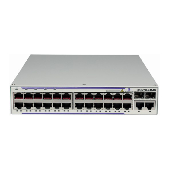
Preliminary 9/28/09 OmniSwitch 6250-24M/24MD The OS6250-24M chassis contains the following major components: System status LEDs • (24) Unshared 10/100Base-T ports • (2) Fixed 100/1000BaseX or SFP+ Stacking Ports • (2) Combo 10/100/1000Base-T or 100/1000BaseX • Internal AC Power Supply (24M) •... - Page 30 Preliminary 9/28/09 OmniSwitch 6250-24M/24-MD Front Panel OS6250-24M/24-MD Front Panel Item Description System Status LEDs Provides status on hardware, software, primary and redundant power. 10/100/1000BaseT or 100/1000BaseX SFP Combo Ports Two 10/100/1000BaseT or SFP combo ports for various supported SFP transceivers. 10/100BaseT RJ-45 Ports 10/100BaseT non-combo ports.
-
Page 31: Omniswitch 6250-24M/24-Md Rear Panel
Preliminary 9/28/09 OmniSwitch 6250-24M/24-MD Rear Panel Note. The figure shows a pre-production version of the chassis without product, safety, and compliance information labels. All production versions of the chassis have these labels. OS6250-24M Rear Panel OS6250-24MD Rear Panel Item Description Push Button When pushed all LEDs will turn off and the LED of the Stack ID will remain lit. - Page 32 Preliminary 9/28/09 Item Description SFP Uplink or SFP+ Stacking Ports Two SFP or SFP+ ports to be used for uplink or stacking. BPS Connector Power Supply Connector Internal AC power supply. DC Power Supply Connector Refer to “Status LEDs” on page 2-20 for LED status information.
- Page 33 Preliminary 9/28/09 OS6250-24M/24-MD Specifications Total unshared 10/100BaseT 24 (1-24) ports per switch Total combo ports per switch 2 (25-26) Total fixed SFP ports per switch 2 (27-28 in Uplink mode), (STK A, STK B Stacking mode) Total 802.3af PoE ports per switch Flash memory size 128 MB...
-
Page 34: Omniswitch 6250-24
Preliminary 9/28/09 OmniSwitch 6250-24 The front panel of the OS6250-24 chassis contains the following major components: System status LEDs • (24) Unshared 10/100Base-T ports • (2) Combo 10/100/1000Base-T or 100/1000BaseX • (2) HDMI Stacking Ports • Internal AC Power Supply •... - Page 35 Preliminary 9/28/09 OmniSwitch 6250-24 Front Panel OS6250-24 Front Panel Item Description System Status LEDs Provides status on hardware, software, primary and redundant power. 10/100/1000BaseT or 100/1000BaseX SFP Combo Ports Two 10/100/1000BaseT or SFP combo ports for various supported SFP transceivers. 10/100BaseT RJ-45 Ports 10/100BaseT non-combo ports.
-
Page 36: Omniswitch 6250-24 Rear Panel
Preliminary 9/28/09 OmniSwitch 6250-24 Rear Panel Note. The figure shows a pre-production version of the chassis without product, safety, and compliance information labels. All production versions of the chassis have these labels. OS6400-24 Rear Panel Item Description Push Button When pushed all LEDs will turn off and the LED of the Stack ID will remain lit. - Page 37 Preliminary 9/28/09 OS6250-24 Specifications Total unshared 10/100BaseT 24 (1-24) ports per switch Total combo ports per switch 2 (25-26) Total HDMI ports per switch 2 (Stack A, Stack B) Total 802.3af PoE ports per switch Flash memory size 128 MB RAM memory size 256 MB SDRAM Chassis Width...
-
Page 38: Omniswitch 6250-P24
Preliminary 9/28/09 OmniSwitch 6250-P24 The front panel of the OS6250-P24 chassis contains the following major components: System status LEDs • (24) Unshared 10/100Base-T PoE (802.3at first 6 ports and combo, 802.3af last 18) ports • (2) Combo 10/100/1000Base-T or 100/1000BaseX •... - Page 39 Preliminary 9/28/09 OmniSwitch 6250-P24 Front Panel OS6250-P24 Front Panel - Update Item Description System Status LEDs Provides status on hardware, software, primary and redundant power. 10/100/1000BaseT or 100/1000BaseX SFP Combo Ports Two 10/100/1000BaseT or SFP combo ports for various supported SFP transceivers.
-
Page 40: Omniswitch 6250-P24 Rear Panel
Preliminary 9/28/09 OmniSwitch 6250-P24 Rear Panel Note. The figure shows a pre-production version of the chassis without product, safety, and compliance information labels. All production versions of the chassis have these labels. OS6250-P24 Rear Panel Item Description Push Button When pushed all LEDs will turn off and the LED of the Stack ID will remain lit. - Page 41 Preliminary 9/28/09 OS6250-P24 Specifications Total unshared 10/100BaseT 24 (1-24) ports per switch Total combo ports per switch 2 (25-26) Total HDMI ports per switch 2 (StackA, StackB) Total 802.3at PoE ports per 8 (1-6, 25-26) Ports 25 and 26 share PoE with 23 and 24. Only one set switch of ports can have PoE operational at a time.
-
Page 42: Led Status
Preliminary 9/28/09 LED Status State Description Solid Green Normal Operation. Solid Amber Operating Temperature Exceeded. Solid Green Primary unit in a stack or standalone switch. Solid Amber Secondary unit in a stack. Switch is idle. (not primary or secondary) Solid Green P/S Normal Operation. -
Page 43: Os6250 - Power Supplies
Preliminary 9/28/09 OS6250 - Power Supplies Internal 30W AC System Power Supply (see “Internal AC Power Supply” on page 2-22) • Internal 30W DC System Power Supply (see “Internal DC Power Supply” on page 2-23) • External 42W AC Power Brick (see “PS-42W-AC Power Brick”... -
Page 44: Internal Ac Power Supply
Preliminary 9/28/09 Internal AC Power Supply Provides system power for the OmniSwitch 6250 Series switches. P/S Component Description Model Internal AC Power Supply Provides System Power For OS6250-8M/24/24M Input Voltage Range 100-240 VAC Rated Frequency 50 to 60 Hz Inrush Current 0.9 A Maximum Output Power 30 W... -
Page 45: Internal Dc Power Supply
Preliminary 9/28/09 Internal DC Power Supply Provides system power for the OmniSwitch 6250 Series switches. P/S Component Description Model Internal DC Power Supply Provides System Power For OS6250-24MD Input Voltage Range -40 to -60VDC Input Current 2.0 A Maximum Output Power 30 W Output Voltage 12.0 VDC... -
Page 46: Ps-42W-Ac Power Brick
Preliminary 9/28/09 PS-42W-AC Power Brick Provides system power and can be installed as a redundant system power supply. 42W, AC Power Brick P/S Component Description Model PS-42W-AC Provides Redundant System OS6250-24/24M/24MD Power For Input Voltage Range 100-240 VAC Rated Frequency 50 to 60 Hz Input Current 1.1 A (maximum) -
Page 47: Ps-30W-Dc Power Brick
Preliminary 9/28/09 PS-30W-DC Power Brick Povides system power and can be installed as a redundant system power supply. 30W, 24/-48VDC System Power Brick - Update P/S Component Description Model PS-30W-DC Provides Redundant System OS6250-24/24M/24MD Power For Input Voltage Range -40 to -60 VDC Input Current Maximum Output Power 30 W... -
Page 48: Ps-225W-Ac-P Poe Power Supply Module
Preliminary 9/28/09 PS-225W-AC-P PoE Power Supply Module Provides system and Power over Ethernet and can be installed as either the primary or backup power supply. 225W, -54.5VDC PoE Power Brick P/S Component Description Model PS-225W-AC-P Provides System and PoE Power OS6250-P24 Input Voltage Range 100 to 240 VAC... -
Page 49: Power Supply Tray
9/28/09 Power Supply Tray Alcatel-Lucent requires the use of the power supply tray when connecting external power supplies. The shelf can be attached directly to the back or side of the chassis and rack mounted. OS6250 Power Supply Shelf - Update... -
Page 50: Ac Power Cords
Preliminary 9/28/09 AC Power Cords Since the power cord is the switch’s only disconnect device, it should be plugged into an easily accessible outlet. In the event that your power cord is lost or damaged, refer to the specifications below. Specifications The power cord included with this product contains three (3) insulated #18AWG stranded copper wires and is rated between 85-265 VAC (region dependent), 10 amps with a nominal length of 2 meters. -
Page 51: Dc Power Specifications
Preliminary 9/28/09 DC Power Specifications OS6250-24MD Internal DC Power Supply The internal DC power supply has the following additional considerations. Refer to the installation steps described in “DC Power Supply Considerations” on page 3-22 Connect to a -48V or -60V reliably grounded DC SELV source. •... -
Page 52: Stacking Cables
Preliminary 9/28/09 Stacking Cables The following cables and transceivers can used for stacking switches into a virtual chassis. Depending on the length and stacking requirements, either copper or fiber can be used. Enterprise models support two HDMI stacking ports and Metro models support two SFP+ stacking ports for use with SFP+ transceivers or direct attached SFP+ copper cables. -
Page 53: Console Port
Preliminary 9/28/09 Console Port The console port, located on the chassis front panel, provides a console connection to the switch and is required when logging into the switch for the first time. By default, this RJ-45 connector provides a DTE console connection. -
Page 54: Port Pinouts
Preliminary 9/28/09 Port Pinouts RJ-45 Console Port – Connector Pinout Pin Number Signals as DTE Console Port Ground Ground 10/100 Ethernet Port – RJ-45 Pinout (non-PoE) Pin Number Description not used not used not used not used Gigabit Ethernet Port – RJ-45 Pinout Pin Number Description BI_DB+... -
Page 55: 10/100/1000 Mbps Power Over Ethernet Port - Rj-45 Pinout
Preliminary 9/28/09 10/100/1000 Mbps Power over Ethernet Port – RJ-45 Pinout Pin Number Description RX+ (-VDC) RX- (-VDC) TX+ (+VDC) TX- (+VDC) Overtemp Condition (Verify all this) The OmniSwitch 6250 is designed to operate within a specified operating temperature as noted under the specifications section. - Page 56 Preliminary 9/28/09 page 2-34 OmniSwitch 6250 Series Hardware Users Guide September 2009...
-
Page 57: Chapter 3 Mounting Os6250 Switches
Preliminary 9/28/09 3 Mounting OS6250 Switches This chapter covers different mounting and installation options for OS6250 switches. Anti-Static Warning. Before handling any components, free yourself of static by wearing a grounding strap, or by grounding yourself properly. Static discharge can damage the switch and the backup power supply. -
Page 58: General Installation Recommendations
Preliminary General Installation Recommendations Mounting OS6250 Switches 9/28/09 General Installation Recommendations Cooling Recommendations OS6250 switches are convection-cooled. Although air flow is not mandatory for switch operation, the best way to ensure proper cooling is to provide some ambient air flow over the switch whenever possible (e.g., from room fans, etc.). -
Page 59: Recommended Clearances
Preliminary Mounting OS6250 Switches General Installation Recommendations 9/28/09 Recommended Clearances Always allow adequate clearance at the front, rear, top, and sides of the switch. The following table shows the recommended minimum clearances for adequate chassis cooling and access to cabling and components at the front and rear of the chassis. -
Page 60: Power Supply Information
Preliminary Power Supply Information Mounting OS6250 Switches 9/28/09 Power Supply Information Before getting started, please note that OmniSwitch 6250 Series power supplies can be installed in a number of different configurations. For example: Non-redundant system power - Provides power requirements to the chassis, with no power supply •... -
Page 61: Assembling Os6250 Switches
Preliminary Mounting OS6250 Switches Assembling OS6250 Switches 9/28/09 Assembling OS6250 Switches Assembly Guidelines Depending on the model, power supplies, and mounting requirements, the OS6250 can be mounted in a variety of ways. Power supply trays can be mounted on the side or back of the chassis or both. •... - Page 62 Preliminary Assembling OS6250 Switches Mounting OS6250 Switches 9/28/09 Attach the slot-brackets to the front and rear of the chassis using the four attachment screws (M3 flat head) provided for each bracket. Slot-Bracket Attachment Attach slide-bracket to front of the power supply tray using the four attachment screws (M3 flat head). Slide bracket Slide-Bracket Attachment page 3-6...
- Page 63 Preliminary Mounting OS6250 Switches Assembling OS6250 Switches 9/28/09 Attach the power supply tray extension bracket to the rear of the power supply tray using one screw (M3 pan head) and then attach the slide bracket to the extension with two screws (M3 pan head). Attach power supply tray extension bracket to the rear of the chassis.
- Page 64 Preliminary Assembling OS6250 Switches Mounting OS6250 Switches 9/28/09 Place bracket plate over the front brackets and secure with thumb screws. Secure power supply tray to chassis with bracket plate and screws. Secure Front Bracket with Plate Skip to “Securing Power Supplies in Power Supply Tray” on page 3-12 page 3-8 OmniSwitch 6250 Series Hardware Users Guide September 2009...
-
Page 65: Attaching Two Chassis Side-By-Side
Preliminary Mounting OS6250 Switches Assembling OS6250 Switches 9/28/09 Attaching Two Chassis Side-by-Side Two chassis can be assembled side-by-side with the power supply trays attached to the back of the chas- sis, if necessary, for mounting into a standard 19-inch rack as show in the figure below. Rear center brackets. - Page 66 Preliminary Assembling OS6250 Switches Mounting OS6250 Switches 9/28/09 Align the chassis and slide both front and rear center brackets together. Slide chassis together Slide Chassis Together Place bracket plate over front and rear brackets and secure with thumb screws. Bracket Plate and Screws Secure Front and Back with Bracket Plate page 3-10 OmniSwitch 6250 Series Hardware Users Guide...
-
Page 67: Attaching Power Supply Tray To Rear Of Chassis
Preliminary Mounting OS6250 Switches Assembling OS6250 Switches 9/28/09 Attaching Power Supply Tray to Rear of Chassis To secure a power supply tray to the rear of the chassis, follow the steps below. Insert the two tabs at the base of the tray into the slots provided at the bottom-rear portion of the switch chassis. -
Page 68: Securing Power Supplies In Power Supply Tray
Preliminary Assembling OS6250 Switches Mounting OS6250 Switches 9/28/09 Securing Power Supplies in Power Supply Tray Power Supply Brick Installation Place the power supply into the power supply tray. Power Supply Power Supply Tray Place Power Supply Into Tray Position the power supply bracket over the power supply ensuring the tabs are placed over the power supply holding it in place. -
Page 69: Power Supply Module Installation
Preliminary Mounting OS6250 Switches Assembling OS6250 Switches 9/28/09 Secure the bracket and power supply using the retaining strap. Secure the retaining strap to the power supply tray using the attachment screws (provided). Retaining strap Retaining Strap Screws Secure Power Brick With Strap Power Supply Module Installation Place the power supply into the power supply tray with the connector pins facing the chassis. -
Page 70: Mounting Os6250 Switches
• chassis and position it on the rack, and a second person to secure the chassis to the rack using attachment screws. (Please note that Alcatel-Lucent does not provide rack-mount screws. Use the screws supplied by the rack vendor.) To prevent a rack from becoming top heavy, it is recommended that you install heavier equipment at •... - Page 71 Preliminary Mounting OS6250 Switches Mounting OS6250 Switches 9/28/09 Once the holes are aligned, insert a rack mount screw (not provided) through the bottom hole of each flange. Tighten both screws until they are secure. When rack mounting, a clearance of 0.875 inches is recommended above the chassis.
-
Page 72: General Table-Mounting Guidelines
Preliminary Mounting OS6250 Switches Mounting OS6250 Switches 9/28/09 Table-Mounting OS6250 Switches General Table-Mounting Guidelines OmniSwitch 6250 Series switches can be installed freestanding as tabletop-mounted units. If you will be table-mounting your switch(es), refer to the important guidelines below before installing. When choosing a location for the switch, be sure that adequate clearance has been provided for chassis •... - Page 73 Preliminary Mounting OS6250 Switches Mounting OS6250 Switches 9/28/09 If preferred, mount the complete switch assembly to the table by inserting attachment screws (not provided) through the flat portion of the mounting brackets and into the mounting surface. Do not over- tighten.
-
Page 74: Wall-Mounting The Os6250-8M
Preliminary Mounting OS6250 Switches Mounting OS6250 Switches 9/28/09 Wall-Mounting the OS6250-8M The OmniSwitch OS6250-8M switch can also be installed as a wall-mounted unit. Note. Only the OS6250-8M supports wall-mounting. General Wall-Mounting Guidelines When choosing a location for the switch, be sure that adequate clearance has been provided for chassis •... -
Page 75: Wall-Mounting Installation
Preliminary Mounting OS6250 Switches Mounting OS6250 Switches 9/28/09 Wall-Mounting Installation Follow the proper assembly instructions based on the configuration of the chassis and power supply trays described in “Assembling OS6250 Switches” on page 3-5. Locate the wall-mount brackets provided in your ship kit and orient the brackets so that the rubber bumpers are facing down. - Page 76 Preliminary Mounting OS6250 Switches Mounting OS6250 Switches 9/28/09 Note. Wall fasteners are not provided with your switch and will vary depending on the type of wall surface. Be sure to use fasteners that are approved for the full weight of the chassis assembly. Consult fastener specifications for full details.
-
Page 77: Connecting Chassis To Power Source
Preliminary Mounting OS6250 Switches Connecting Chassis to Power Source 9/28/09 Connecting Chassis to Power Source AC Power Supply Connections Since the power cord is the switch’s only disconnect device, it should be plugged into an easily accessible outlet. In the event that your power cord is lost or damaged, refer to the specifications below. Powering On a Chassis Follow the steps below to power on the chassis using and AC power source: Connect the IEC-60320-C15 end of the supplied power cord to the primary and optional redundant... - Page 78 Preliminary Connecting Chassis to Power Source Mounting OS6250 Switches 9/28/09 OS6250-24MD Internal DC Power Supply Connections The internal DC power supply has the following additional considerations. Refer to the installation steps described in “OS6250-24MD Internal DC Power Supply Connections” on page 3-22 Connect to a -48V or -60V reliably grounded DC SELV source.
-
Page 79: Securing The Redundant Dc Power Supply Connector
Mounting OS6250 Switches Connecting Chassis to Power Source Securing the Redundant DC Power Supply Connector If a redundant DC power supply is to be used, follow the steps below to securely mount the redundant DC power connector to the power supply tray. Secure the DC power connector bracket to the power supply tray using the screws provided. -
Page 80: Installing Dc Power Source Wire Leads
Connecting Chassis to Power Source Mounting OS6250 Switches Installing DC Power Source Wire Leads The DC power supply on your switch contains a power connector with three (3) square slots for connect- ing the positive, negative, and ground wires from a DC power source. DC Power Connectors Side Screws for Connector Removal OmniSwitch DC Power Supply Connector... - Page 81 Mounting OS6250 Switches Connecting Chassis to Power Source Push the wire in far enough such that it reaches the back wall of the connector, about a half inch inside. Ground Wire Attaching the Ground Wire Tighten the clamp by tightening the screw above the slot into which you inserted the wire lead. The wire lead should be securely attached inside the connector.
-
Page 82: Hot-Swapping Power Supplies
Connecting Chassis to Power Source Mounting OS6250 Switches Hot-Swapping Power Supplies Hot swapping is supported on models with redundant power supplies. In order to support the hot swap- ping of power supplies, the switch must have: An operational redundant power supply •... -
Page 83: Booting 6250 Series Switches
If any of the LED state differs from the states shown in the table above, refer to page 2-7 for more infor- mation. Contact Alcatel-Lucent Customer Support if the LED state persists. For information on logging in and configuring your OmniSwitch 6250 Series switch, refer to the OmniSwitch 6250 Series Getting Started Guide. -
Page 84: Console Port
Preliminary Console Port Booting 6250 Series Switches 9/28/09 Console Port The console port, located on the chassis front panel, provides a console connection to the switch and is required when logging into the switch for the first time. By default, this RJ-45 connector provides a DTE console connection. - Page 85 Preliminary Booting 6250 Series Switches Console Port 9/28/09 To change the stop bits value, enter boot serialstopbits, followed by the number of stop bits. Options include 1 (default) and 2. For example: Boot > boot serialstopbits 2 Verify your current changes by entering show at the boot prompt: Boot >...
-
Page 86: Viewing The Power Supply Status
Preliminary Console Port Booting 6250 Series Switches 9/28/09 Viewing the Power Supply Status The switch constantly monitors the power supply operation. If either the primary or backup power source (optional) unexpectedly shuts down, the switch sends out a notification to the user. In addition, the power LED on the chassis front panel displays solid amber. -
Page 87: Monitoring The Chassis
Preliminary Booting 6250 Series Switches Monitoring the Chassis 9/28/09 Monitoring the Chassis OmniSwitch 6250 Series switches can be monitored and managed via the console port using Command Line Interface (CLI) commands. The switches can also be monitored and managed via the Ethernet using CLI commands, WebView, SNMP, and OmniVista. -
Page 88: Checking The Fan Status
Preliminary Monitoring the Chassis Booting 6250 Series Switches 9/28/09 Checking the Fan Status To check the current status for all six fans in the chassis, use the show fan command. For example: -> show fan Chassis Fan Status -------+---+----------- Running Running Running Running... -
Page 89: Using Leds To Visually Monitor The Chassis
Preliminary Booting 6250 Series Switches Monitoring the Chassis 9/28/09 Using LEDs to Visually Monitor the Chassis The front and rear panel of OmniSwitch 6250 Series switches provides status LEDs that are useful in visu- ally monitoring the status of the switches. LEDs include: Ethernet Port LEDs •... - Page 90 Preliminary Monitoring the Chassis Booting 6250 Series Switches 9/28/09 page 4-8 OmniSwitch 6250 Series Hardware Users Guide September 2009...
-
Page 91: Installing And Managing Power Over Ethernet
OmniSwitch 6250 Series chassis. Important. Alcatel-Lucent recommends that PoE-enabled switches with attached IP telephones should have operational power supply redundancy at all times for 911 emergency requirements. In addition, both the switch and the power supply should be plugged into an Uninterruptible Power Source (UPS). -
Page 92: In This Chapter
Note. You can also monitor all chassis components and manage many chassis features, including Power over Ethernet, with WebView, Alcatel-Lucent’s embedded web-based device management application. WebView is an interactive and easy-to-use GUI that can be launched from the OmniVista or a web browser. -
Page 93: Power Over Ethernet Specifications
Power over Ethernet Specifications 9/28/09 Power over Ethernet Specifications The table below lists general specifications for Alcatel-Lucent’s Power over Ethernet support. For more detailed power supply and Power Source Equipment (PSE) specifications, refer to Chapter 2, “OmniSwitch 6250 Series Chassis and Hardware Components.”... -
Page 94: Viewing Poe Power Supply Status
Preliminary Viewing PoE Power Supply Status Installing and Managing Power over Ethernet (PoE) 9/28/09 Viewing PoE Power Supply Status To view the current status of power supplies installed, use the show power command, as shown below: -> show power Slot Wattage Type Status... -
Page 95: Configuring Power Over Ethernet Parameters
Preliminary Installing and Managing Power over Ethernet (PoE) Configuring Power over Ethernet Parameters 9/28/09 Configuring Power over Ethernet Parameters Power over Ethernet Defaults The following table lists the defaults for PoE configuration: Parameter Description Command(s) Default Value/Comments PoE operational status lanpower start lanpower stop Disabled... -
Page 96: Configuring The Total Power Allocated To A Port
Preliminary Configuring Power over Ethernet Parameters Installing and Managing Power over Ethernet (PoE) 9/28/09 Disabling PoE To disable PoE on a particular slot or port, use the lanpower stop command. To disable PoE on a specific PoE-capable port, enter a slot/port number. For example: ->... -
Page 97: Setting Port Priority Levels
Preliminary Installing and Managing Power over Ethernet (PoE) Configuring Power over Ethernet Parameters 9/28/09 To increase or decrease the total power allocated to a slot, use the lanpower maxpower command. Since you are setting the power allowance for an individual slot, you must specify a slot number in the command line. -
Page 98: Understanding Priority Disconnect
Preliminary Understanding Priority Disconnect Installing and Managing Power over Ethernet (PoE) 9/28/09 Understanding Priority Disconnect The priority disconnect function differs from the port priority function described on page 5-7 in that it applies only to the addition of powered devices (PDs) in tight power budget conditions. Priority discon- nect is used by the system software in determining whether an incoming PD will be granted or denied power when there are too few watts remaining in the PoE power budget for an additional device. -
Page 99: Priority Disconnect Is Enabled; Same Priority Level On All Pd
Preliminary Installing and Managing Power over Ethernet (PoE) Understanding Priority Disconnect 9/28/09 Priority Disconnect is Enabled; Same Priority Level on All PD Reminder. Priority disconnect examples are applicable only when there is inadequate power remaining to power an incoming device. When a PD is being connected to a port with the same priority level as all other in the slot, the physical port number is used to determine whether the incoming PD will be granted or denied power. -
Page 100: Priority Disconnect Is Disabled
Preliminary Understanding Priority Disconnect Installing and Managing Power over Ethernet (PoE) 9/28/09 Priority Disconnect is Disabled Reminder. Priority disconnect examples are applicable only when there is inadequate power remaining to power an incoming device. When priority disconnect is disabled, power will be denied to any incoming PD, regardless of its port priority status (i.e., low, high, and critical) or physical port number (i.e., 1/1). -
Page 101: Monitoring Power Over Ethernet Via Cli
Preliminary Installing and Managing Power over Ethernet (PoE) Monitoring Power over Ethernet via CLI 9/28/09 Monitoring Power over Ethernet via CLI To monitor current PoE statistics and settings, use the show lanpower command. The command output displays a list of all current PoE-capable, along with the following information for each port: Maximum power allocated to the port, in milliwatts •... - Page 102 Preliminary Monitoring Power over Ethernet via CLI Installing and Managing Power over Ethernet (PoE) 9/28/09 page 5-12 OmniSwitch 6250 Series Hardware Users Guide September 2009...
-
Page 103: Managing Omniswitch 6250 Series Stacks
Preliminary 9/28/09 6 Managing OmniSwitch 6250 Series Stacks In addition to their working as individual stand-alone switches, OmniSwitch 6250 Series switches can also be linked together to work as a single virtual chassis known as a stack. With stacks, users can easily expand their switching capacity simply by adding additional switches to the stack. -
Page 104: In This Chapter
Note. You can also manage and monitor OmniSwitch 6250 Series stacks through WebView, Alcatel-Lucent’s embedded web-based device management application. WebView is an interactive and easy-to-use GUI that can be launched from OmniVista or a web browser. Please refer to WebView’s online documentation for more information. -
Page 105: Omniswitch 6250 Stacking Specifications
Preliminary Managing OmniSwitch 6250 Series Stacks OmniSwitch 6250 Stacking Specifications 9/28/09 OmniSwitch 6250 Stacking Specifications The following table lists OmniSwitch 6250 Stacking specifications. Models Supporting Stacking (Metro and Enterprise switches cannot be mixed in the same stack) Maximum Switches in a Stack Stacking Cable Lengths - Copper 30cm 60cm... -
Page 106: Omniswitch 6250 Series Stack Overview
Preliminary OmniSwitch 6250 Series Stack Overview Managing OmniSwitch 6250 Series Stacks 9/28/09 OmniSwitch 6250 Series Stack Overview Users can configure up to four OmniSwitch 6250 Series switches into a single virtual chassis known as a stack. With stacks, switching capacity can be easily expanded simply by adding additional switches to the stack. - Page 107 Preliminary Managing OmniSwitch 6250 Series Stacks Roles Within the Stack 9/28/09 Important Note. For management module redundancy to work effectively, the software on all switches operating in the stack must be synchronized at all times. Refer to “Synchronizing Switches in a Stack” on page 6-37 for more information.
- Page 108 Preliminary Roles Within the Stack Managing OmniSwitch 6250 Series Stacks 9/28/09 A stack of two OmniSwitch 6250 Series switches is operating normally. The stack consists of a primary Primary module and a secondary module. (The software on both elements in the stack is synchronized.) Secondary The primary management module fails or is taken Offline...
-
Page 109: Primary Management Module Selection
Preliminary Managing OmniSwitch 6250 Series Stacks Roles Within the Stack 9/28/09 Primary Management Module Selection For a stack of OmniSwitch 6250 Series switches to operate as a virtual chassis, there must be a mecha- nism for dynamically selecting the switch within the stack that will assume the primary management role. OmniSwitch 6250 Series switches use three different methods for selecting the primary switch. - Page 110 Preliminary Roles Within the Stack Managing OmniSwitch 6250 Series Stacks 9/28/09 Using Saved Slot Information The saved slot number is the slot number the switch will assume following a reboot. This information is stored in a switch’s boot.slot.cfg file; the switch reads its slot number assignment from this file at bootup and assumes the specified slot number within the stack.
- Page 111 Preliminary Managing OmniSwitch 6250 Series Stacks Roles Within the Stack 9/28/09 Using Switch Uptime A user can override both the MAC address and saved slot methods for determining a stack’s primary management module. This is done by controlling the uptime of switches in the stack. If all elements of a stack are powered off, the user can force a particular switch to become primary by powering on that switch and waiting a minimum of 15 seconds before powering on any other switches.
-
Page 112: Secondary Management Module Selection
Preliminary Roles Within the Stack Managing OmniSwitch 6250 Series Stacks 9/28/09 Secondary Management Module Selection In order to provide effective management module redundancy, all OmniSwitch 6250 Series stacked configurations dynamically assign a backup, or secondary, management module during the boot process. OmniSwitch 6250 Series stacks use two different methods for selecting the secondary switch. - Page 113 Preliminary Managing OmniSwitch 6250 Series Stacks Roles Within the Stack 9/28/09 Using Saved Slot Information If a stack with preassigned slot information for each switch is booted, the switch with the second lowest slot value is assigned the secondary management role. For example, if a stack of four switches is booted and the preassigned slot values for each switch are 1, 2, 3, and 4, the switch with the slot value of 2 is assigned the secondary role.
-
Page 114: Idle Module Role
Preliminary Roles Within the Stack Managing OmniSwitch 6250 Series Stacks 9/28/09 Idle Module Role Switches that are not assigned either the primary or secondary role in a stack are, by default, assigned the role of idle modules. These idle modules operate similarly to Network Interface (NI) modules in a chassis- based switch. -
Page 115: Pass-Through Mode
Preliminary Managing OmniSwitch 6250 Series Stacks Roles Within the Stack 9/28/09 Pass-Through Mode The pass-through mode is a state in which a switch has attempted to join a stack but has been denied primary, secondary, and idle status. When a switch is in the pass-through mode, its Ethernet are brought down (i.e, they cannot pass traffic). -
Page 116: Recovering From Pass-Through Mode (Duplicate Slot Numbers)
Preliminary Roles Within the Stack Managing OmniSwitch 6250 Series Stacks 9/28/09 To avoid a pass-through condition following a reboot, make sure that all saved slot values for the stack are unique. Use the stack set slot command. For example, change the saved slot value for the idle switch in slot 3 from 2 to 3: ->... - Page 117 Preliminary Managing OmniSwitch 6250 Series Stacks Roles Within the Stack 9/28/09 To resolve this pass-through condition, simply assign slot 1001 a new saved slot value and reboot the module. This can be done in either of two ways: Use the stack set slot command to assign the new value, then use the reload pass-through...
- Page 118 Preliminary Roles Within the Stack Managing OmniSwitch 6250 Series Stacks 9/28/09 In some pass-through conditions (for example, larger stacks where multiple switches are in pass-through mode), it might be desirable to correct any duplicate saved slot assignments and then reboot the entire stack.
-
Page 119: Stack Cabling
Preliminary Managing OmniSwitch 6250 Series Stacks Stack Cabling 9/28/09 Stack Cabling Switches in a stack are connected to each other by stacking cables. These stacking cables provide high- speed, dual-redundant links between switches in a stack. Stacking cables for OmniSwitch 6250 Series switches must be connected in an A-B pattern. In other words, the cable connected to stacking port A of one switch must be connected to stacking port B of the adjacent switch. -
Page 120: Redundant Stacking Cable Connection
Preliminary Stack Cabling Managing OmniSwitch 6250 Series Stacks 9/28/09 Redundant Stacking Cable Connection OmniSwitch 6250 Series switches allow redundant stacking cable connections between the top-most and bottom-most switches in a stack. Important. For a stacked configuration to have effective redundancy, a redundant stacking cable must be installed between the upper-most and bottom-most switch in the chassis at all times. -
Page 121: Checking Redundant Stacking Cable Status
Preliminary Managing OmniSwitch 6250 Series Stacks Stack Cabling 9/28/09 Redundant stacking cables provide a form of dual redundancy. As shown in the figure above, the redun- dant cable allows traffic to flow in the event of a stacking link failure. The redundant cable also provides failover if a switch goes down within the stack. -
Page 122: Slot Numbering
Preliminary Slot Numbering Managing OmniSwitch 6250 Series Stacks 9/28/09 Slot Numbering For a stack of OmniSwitch 6250 Series switches to operate as a virtual chassis, each module in the stack must be assigned a unique slot number. To view the current slot assignments for a stack, use the show ni show module commands. -
Page 123: Dynamic Slot Number Assignment
Preliminary Managing OmniSwitch 6250 Series Stacks Slot Numbering 9/28/09 Dynamic Slot Number Assignment Dynamic slot number assignment occurs when there are no boot.slot.cfg files present in the switches’ /flash directories. This is the case for new, “out of the box,” switches that have not been previously booted. - Page 124 Preliminary Slot Numbering Managing OmniSwitch 6250 Series Stacks 9/28/09 If the switch with the lowest MAC address happens to be the bottom-most module in the stack, slot numbering will not resume from the top of the stack. Instead, the system software will select the second- ary module using the standard method (i.e., the switch connected to the primary’s stacking port A), then continue to number the stack from the bottom up.
-
Page 125: Manual Slot Number Assignment
Preliminary Managing OmniSwitch 6250 Series Stacks Slot Numbering 9/28/09 Manual Slot Number Assignment To manually assign slot numbers to one or more modules in a stack, use the stack set slot command. This command writes slot information to the boot.slot.cfg file located in a switch’s /flash directory. It is this saved slot information that the switch will assume following a reboot. -
Page 126: Reverting To The Dynamic Slot Numbering Model
Preliminary Slot Numbering Managing OmniSwitch 6250 Series Stacks 9/28/09 When the stack comes up following the reboot, the manually-configured slot numbers display as follows: Slot 1 - Primary Slot 2 - Secondary Slot 3 - Idle Slot 4 - Idle Slot 5 - Idle Slot 6 - Idle Slot 7 - Idle... -
Page 127: Hot-Swapping Modules In A Stack
Preliminary Managing OmniSwitch 6250 Series Stacks Hot-Swapping Modules In a Stack 9/28/09 Hot-Swapping Modules In a Stack As with chassis-based switches, NI modules within an OmniSwitch 6250 Series virtual chassis are hot- swappable. NI modules are essentially those modules operating in the stack in idle mode. These modules can be removed from, or added to, an existing stack without disrupting other modules in the stack. -
Page 128: Merging Stacks
Preliminary Hot-Swapping Modules In a Stack Managing OmniSwitch 6250 Series Stacks 9/28/09 Merging Stacks Merging stacks involves connecting two or more operational stacks and attempting to reboot them as a single virtual chassis. In most cases, errors will result. To merge stacks without causing errors, select one stack that is to remain up and running and then add modules from the other stack(s) by following the steps below: Make sure all switches are running the same software version. -
Page 129: Reloading Switches
Preliminary Managing OmniSwitch 6250 Series Stacks Reloading Switches 9/28/09 Reloading Switches Reloading is essentially a soft boot of a switch. Users can reload stacked modules operating in any role— i.e., primary, secondary, idle, and pass-through. Refer to the sections below for more information. Reloading the Primary Management Module If the switch with the primary management role is reloaded, the switch with the secondary role automati- cally takes over primary management functions. - Page 130 Preliminary Reloading Switches Managing OmniSwitch 6250 Series Stacks 9/28/09 If there are only two switches in the stack, the switch that was reloaded (the former primary) assumes the secondary role when it comes back up. In this stack of two OmniSwitch 6250 Series switches, the slot 1 Primary - Slot 1 switch is the primary management module.
-
Page 131: Reloading The Secondary Management Module
Preliminary Managing OmniSwitch 6250 Series Stacks Reloading Switches 9/28/09 Reloading the Secondary Management Module If the switch with secondary management role is reloaded, the idle switch with the lowest slot number will automatically assume the secondary role. The reloaded switch (the former secondary) will assume an idle role when it comes back up. - Page 132 Preliminary Reloading Switches Managing OmniSwitch 6250 Series Stacks 9/28/09 If there are only two switches in the stack, the switch that was reloaded (the former secondary) resumes the secondary role when it comes back up. In this stack of two OmniSwitch 6250 Series switches, the slot 1 Primary - Slot 1 switch is the primary management module.
-
Page 133: Reloading Switches With Idle Roles
Preliminary Managing OmniSwitch 6250 Series Stacks Reloading Switches 9/28/09 Reloading Switches with Idle Roles Similar to reloading Network Interface (NI) modules on chassis-based switches, modules operating in idle status within a stack can be reloaded via the CLI. Note. Any traffic being passed on the module’s Ethernet will be interrupted during the reboot. Other modules within the stack will continue to operate without interruption. -
Page 134: Reloading All Switches In A Stack
Preliminary Reloading Switches Managing OmniSwitch 6250 Series Stacks 9/28/09 Reloading All Switches in a Stack Reloading all switches in the stack is essentially a full reboot of the virtual chassis. This can be useful in restoring a stack’s previously configured topology—i.e., the stack’s saved slot numbers and management roles. - Page 135 Preliminary Managing OmniSwitch 6250 Series Stacks Reloading Switches 9/28/09 No Switches In the Stack Have Saved Slot Information If a full reload is issued and no switches in the stack have unique slot numbers, slot numbers will be assigned beginning with the switch with the lowest MAC address. (This can occur if the boot.slot.cfg file has been deleted from each switch’s /flash directory—e.g., by issuing the stack clear slot command for all...
-
Page 136: Avoiding Split Stacks
Preliminary Reloading Switches Managing OmniSwitch 6250 Series Stacks 9/28/09 Avoiding Split Stacks The term “splitting” a stack refers to the creation of isolated modules within the virtual chassis. A split stack can result from the following conditions: Two or more non-adjacent switches are reloaded simultaneously •... -
Page 137: Changing The Secondary Module To Primary
Preliminary Managing OmniSwitch 6250 Series Stacks Changing the Secondary Module to Primary 9/28/09 Changing the Secondary Module to Primary OmniSwitch 6250 Series stacks allow users to manually force the secondary switch to assume the primary management role. This is referred to as “takeover.” The behavior of a takeover is similar to that of reload- ing the primary management module (see page 6-27). - Page 138 Preliminary Changing the Secondary Module to Primary Managing OmniSwitch 6250 Series Stacks 9/28/09 If there are only two switches in the stack, the former primary switch resumes the secondary role when it comes back up following the takeover. In this stack of two OmniSwitch 6250 Series switches, the slot 1 Primary - Slot 1 switch is the primary management module.
-
Page 139: Synchronizing Switches In A Stack
Preliminary Managing OmniSwitch 6250 Series Stacks Synchronizing Switches in a Stack 9/28/09 Synchronizing Switches in a Stack Management module synchronization refers to the process of copying all files in the /flash/working and /flash/certified directories of the primary management module to the /flash/working and /flash/certified directories of all the other switches in the stack. -
Page 140: Monitoring The Stack
Preliminary Monitoring the Stack Managing OmniSwitch 6250 Series Stacks 9/28/09 Monitoring the Stack As shown in the previous sections, monitoring the current status and operation of all elements in a stack can help users avoid unexpected stack conditions. The table below includes CLI commands that are useful in monitoring stack conditions. -
Page 141: Cli Commands Supported On Both Primary And Secondary Management Modules
Preliminary Managing OmniSwitch 6250 Series Stacks Monitoring the Stack 9/28/09 CLI Commands Supported on Both Primary and Secondary Management Modules Although most CLI commands are executed when logged into the switch with the primary management role, there is a group of commands that is supported when logged in to either the primary or secondary management module. - Page 142 Preliminary Monitoring the Stack Managing OmniSwitch 6250 Series Stacks 9/28/09 page 6-40 OmniSwitch 6250 Series Hardware Users Guide September 2009...
-
Page 143: Regulatory Compliance And Safety Information
Preliminary 9/28/09 A Regulatory Compliance and Safety Information This appendix provides information on regulatory agency compliance and safety for the OmniSwitch 6250 Series switches. Declaration of Conformity: CE Mark This equipment is in compliance with the essential requirements and other provisions of Directive 73/23/EEC and 89/336/EEC as amended by Directive 93/68/EEC. -
Page 144: China Rohs: Hazardous Substance Table
对销售之日的所售产品,本表显示, 阿尔卡特朗讯公司供应链的电子信息产品可能包含这些物质。注意:在所售产 品中可能会也可能不会含有所有所列的部件。 This table shows where these substances may be found in the supply chain of Alcatel-Lucent electronic information products, as of the date of sale of the enclosed product. Note that some of the component types listed above may or may not be a part of the enclosed product. - Page 145 Regulatory Compliance and Safety Information China RoHS: Hazardous Substance Table Products are packaged using one or more of the following packaging materials: Corrugated Cardboard Corrugated Fiberboard Low-Density Polyethylene OmniSwitch 6250 Series Hardware Users Guide September 2009 page A-3...
-
Page 146: Waste Electrical And Electronic Equipment (Weee) Statement
Waste Electrical and Electronic Equipment (WEEE) Statement Regulatory Compliance and Safety Information Waste Electrical and Electronic Equipment (WEEE) Statement The product at end of life is subject to separate collection and treatment in the EU Member States, Norway and Switzerland and therefore marked with the symbol: Treatment applied at end of life of the product in these countries shall comply with the applicable national laws implementing directive 2002/96EC on waste electrical and electronic equipment (WEEE). -
Page 147: Standards Compliance
Regulatory Compliance and Safety Information Standards Compliance Standards Compliance Safety Agency Certifications US UL 60950 • IEC 60950-1:2001; all national deviations • EN 60950-1: 2001; all deviations • CAN/CSA-C22.2 No. 60950-1-03 • NOM-019 SCFI, Mexico • AS/NZ TS-001 and 60950:2000, Australia •... -
Page 148: Fcc Class A, Part 15
Standards Compliance Regulatory Compliance and Safety Information FCC Class A, Part 15 This equipment has been tested and found to comply with the limits for Class A digital device pursuant to Part 15 of the FCC Rules.These limits are designed to provide reasonable protection against harmful inter- ference when the equipment is operated in a commercial environment.This equipment generates, uses, and can radiate radio frequency energy and, if not installed and used in accordance with the instructions in this guide, may cause interference to radio communications. -
Page 149: Vcci
Regulatory Compliance and Safety Information Standards Compliance VCCI This is a Class A product based on the standard of the Voluntary Control Council for Interference by Information Technology Equipment (VCCI). If this equipment is used in a domestic environment, radio disturbance may arise. -
Page 150: Translated Safety Warnings
Translated Safety Warnings Regulatory Compliance and Safety Information Translated Safety Warnings Chassis Lifting Warning Two people are required when lifting the chassis. Due to its weight, lifting the chassis unassisted can cause personal injury. Also be sure to bend your knees and keep your back straight when assisting with the lift- ing of the chassis. -
Page 151: Installation Warning
Regulatory Compliance and Safety Information Translated Safety Warnings Installation Warning Only personnel knowledgeable in basic electrical and mechanical procedures should install or maintain this equipment. Français: Toute installation ou remplacement de l'appareil doit être réalisée par du personnel qualifié et compétent. - Page 152 Translated Safety Warnings Regulatory Compliance and Safety Information Cleaning and dressing of grounding points during installation is strongly recommended. Also, do not • forget the antioxidant. To ground the equipment properly, connect a Panduit Corporation UL listed Lug, P/N: LCD8-10A- •...
-
Page 153: Read Important Safety Information Warning
Regulatory Compliance and Safety Information Translated Safety Warnings Read Important Safety Information Warning This guide contains important safety information about which you should be aware when working with hardware components in this system. You should read this guide before installing, using, or servicing this equipment. -
Page 154: Wrist Strap Warning
Français: L'électricité statique (ESD) peut endommager les composants du commutateur. Pour cette raison Alcatel-Lucent joint à l'envoi du châssis un bracelet antistatique à brancher sur la prise mise à la terre située en bas à droite du commutateur. Vous devrez mettre ce bracelet avant toute intervention hard- ware. -
Page 155: Instrucciones De Seguridad En Español
Deseche las baterías usadas según las instrucciones del fabricante. Las instrucciones del fabricante son como sigue: Devuelva el módulo con la batería del litio a Alcatel-Lucent. La batería del litio será substitu- ida en la fábrica de Alcatel-Lucent. -
Page 156: Advertencia Sobre Una Apropiada Conexión A Tierra
Instrucciones de seguridad en español Regulatory Compliance and Safety Information Advertencia sobre una apropiada conexión a tierra Para evitar peligro de descargas: El cable de alimentación debe estar conectado a una toma de alimentación adecuadamente cableada • y con toma de tierra. Cualquier equipo al cual se conecte este producto debe estar también conectado a tomas de alimentación adecuadamente cableadas.