Alcatel-Lucent OmniSwitch 6250 Hardware User's Manual
Hide thumbs
Also See for OmniSwitch 6250:
- Cli reference manual (2018 pages) ,
- Management manual (346 pages) ,
- User manual (164 pages)

Related Manuals for Alcatel-Lucent OmniSwitch 6250


Summary of Contents for Alcatel-Lucent OmniSwitch 6250
- Page 1 Part No. 060303-10, Rev. F September 2015 OmniSwitch 6250 Hardware Users Guide enterprise.alcatel-lucent.com...
- Page 2 This user guide documents the OmniSwitch 6250 for AOS Release 6.7.1. This user guide documents OmniSwitch 6250 hardware, including chassis and associated components. The specifications described in this guide are subject to change without notice. enterprise.alcatel-lucent.com Alcatel-Lucent and the Alcatel-Lucent Enterprise logo are trademarks of Alcatel-Lucent.
-
Page 3: Table Of Contents
Product Documentation ....................xv Technical Support ......................xv Documentation Feedback ....................xv ......................1-1 Chapter 1 OmniSwitch 6250 Chassis Configurations ....................1-2 OmniSwitch 6250 Feature Overview ................1-3 Security Features ......................1-3 Applications ........................1-3 Availability Features .......................1-4 Software Rollback ....................1-4 Hot Swapping ......................1-4 Hardware Monitoring ....................1-5 Backup Power Supplies ....................1-5... - Page 4 Specifying the Switch’s Location ..............1-9 Viewing Your Changes ....................1-9 Saving Your Changes ....................1-9 ..........3-1 Chapter 3 OmniSwitch 6250 Chassis and Hardware Components OmniSwitch 6250-8M .....................3-3 OmniSwitch 6250-8M Rear Panel ................3-5 OmniSwitch 6250-24M/24MD ..................3-7 OmniSwitch 6250-24M/24-MD Rear Panel ............3-9 OmniSwitch 6250-24 ....................3-12 OmniSwitch 6250-24 Rear Panel ................3-14...
- Page 5 OS6250-REAR-MNT - Mounting Instructions ..........4-19 Steps ........................4-19 Completed Assembly .....................4-20 Table-Mounting OS6250 Switches ................4-21 General Table-Mounting Guidelines ...............4-21 Table-Mounting Installation ................4-21 Wall-Mounting the OS6250-8M ................4-23 General Wall-Mounting Guidelines ..............4-23 OS6250-WALL-MNT - Wall-Mounting Installation ........4-24 OmniSwitch 6250 Hardware Users Guide September 2015...
- Page 6 Installing DC Power Source Wire Leads ............4-29 Hot-Swapping Power Supplies ................4-31 Chapter 5 Booting 6250 Switches ....................5-1 Booting an OmniSwitch 6250 ..................5-1 Console Port ........................5-2 Serial Connection Default Settings ................5-2 Modifying the Serial Connection Settings ...............5-2 Viewing the Power Supply Status ..............5-4 Monitoring the Chassis ....................5-5...
- Page 7 ................7-1 Chapter 7 Managing OmniSwitch 6250 Stacks In This Chapter ........................7-2 OmniSwitch 6250 Stacking Specifications ..............7-3 Changing Stacking Mode on Metro Models ............7-3 OmniSwitch 6250 Stack Overview .................7-4 Roles Within the Stack ....................7-4 Primary and Secondary Management Modules ............7-4 Primary Management Module Selection ............7-7...
- Page 8 Advertencia sobre una apropiada conexión a tierra ........A-14 Leer “información importante de seguridad” ..........A-14 Advertencia de acceso restringido ..............A-14 Advertencia de pulsera antiestática ..............A-14 Clase de seguridad ..................A-14 viii OmniSwitch 6250 Hardware Users Guide September 2015...
-
Page 9: About This Guide
About This Guide This OmniSwitch 6250 Hardware Users Guide describes your switch hardware components and basic switch hardware procedures. Supported Platforms The information in this guide applies to the following products: • OmniSwitch 6250-8M • OmniSwitch 6250-24M OmniSwitch 6250-24MD •... - Page 10 OmniSwitch 6600 Series • OmniSwitch 6800 Series • OmniSwitch 6850 Series • OmniSwitch 6855 Series • • OmniSwitch 7700 • OmniSwitch 7800 • OmniSwitch 8800 • OmniSwitch 9000 Series OmniStack • OmniAccess • page x OmniSwitch 6250 Hardware Users Guide September 2015...
-
Page 11: Who Should Read This Manual
CLI commands that pertain directly to hardware configuration, but it is not intended as a software users guide. There are several OmniSwitch 6250 users guides that focus on switch software configuration. Consult those guides for detailed information and examples for configuring your switch software to operate in a live network environment. -
Page 12: How Is The Information Organized
How is the Information Organized? This users guide provides an overview of OmniSwitch 6250 switches, specifications of the hardware components, steps for setting up and managing OmniSwitch 6250 switches, and an overview and proce- dures for managing Power over Ethernet (PoE). - Page 13 802.1Q, VLANs, and Spanning Tree. The Network Configuration Guide contains overview information, procedures and examples on how standard network- ing technologies are configured in the OmniSwitch 6250. Anytime The OmniSwitch CLI Reference Guide contains comprehensive information on all CLI commands supported by the switch.
-
Page 14: Related Documentation
Related Documentation About This Guide Related Documentation The following are the titles and descriptions of all the OmniSwitch 6250 user manuals: OmniSwitch 6250 Getting Started Guide • Describes the hardware and software procedures for getting an OmniSwitch 6250 switch up and running. -
Page 15: Product Documentation
OmniSwitch and other Alcatel-Lucent data enterprise products. All user guides for the OmniSwitch Series are included on the Alcatel-Lucent public website. This website also includes user guides for other Alcatel-Lucent Enterprise products. The latest user guides can be found on our website at: http://enterprise.alcatel-lucent.com/UserGuides... - Page 16 Documentation Feedback About This Guide page xvi OmniSwitch 6250 Hardware Users Guide September 2015...
-
Page 17: Chapter 1 Omniswitch 6250
1 OmniSwitch 6250 The Alcatel-Lucent OmniSwitch 6250 is a set of stackable switches designed for Enterprise and Metro applications providing Fast Ethernet connectivity with Advanced Layer 2 software and basic routing. OS6250-8M OS6250-24M OS6250-24MD OS6250-24 OS6250-P24 OS6250 Switches OmniSwitch 6250 Hardware Users Guide... -
Page 18: Chassis Configurations
Chassis Configurations OmniSwitch 6250 Chassis Configurations OmniSwitch 6250 (OS6250) switches offer port densities of up to 24 Fast Ethernet ports. The following OS6250 chassis configurations are available: Metro Models OS6250-8M: Provides eight (8) Fast Ethernet ports, two (2) combo ports, two (2) non-combo fiber •... -
Page 19: Omniswitch 6250 Feature Overview
OmniSwitch 6250 OmniSwitch 6250 Feature Overview OmniSwitch 6250 Feature Overview Security Features OmniSwitch 6250 switches offer extensive security features for network access control, policy enforce- ment and attack containment, enabling fully secure networks and OmniVista Network Management System (NMS) support. Applications Well-suited for traditional enterprise network applications as well as Metro deployments. -
Page 20: Availability Features
OmniSwitch 6250 Availability Features OmniSwitch 6250 switches incorporate advanced Alcatel-Lucent Operating System (AOS) protocols to ensure high availability for mission critical applications. Availability features are hardware- and software- based safeguards that help to prevent the loss of data flow in the unlikely event of a subsystem failure. -
Page 21: Hardware Monitoring
CLI Reference Guide. Backup Power Supplies Some OmniSwitch 6250 switches support an optional backup power supply. Backup power supplies oper- ate in active standby mode. If the primary power supply fails unexpectedly, the backup power supply auto- matically takes up the full power load without disrupting the switch. - Page 22 Availability Features OmniSwitch 6250 page 1-6 OmniSwitch 6250 Hardware Users Guide September 2015...
-
Page 23: Getting Started
Electrical Requirements Note. Alcatel-Lucent switches must be installed by a professional installer. It is the responsibility of the installer to ensure that proper grounding is available and that the installation meets applicable local and national electrical codes. -
Page 24: Unpacking And Installing The Switch
To protect your switch components from damage, read all unpacking recommendations and instructions carefully before beginning. Unpack your OmniSwitch 6250 chassis as close as possible to the location where it will be installed. Items Included Your OmniSwitch 6250 includes the following items: OmniSwitch chassis •... -
Page 25: Airflow Considerations
Chassis Top View Note. Clearance is not required at the top and bottom of the chassis. Mounting the Switch For information on mounting OmniSwitch 6250 switches, refer to Chapter 3, “OmniSwitch 6250 Chassis and Hardware Components.” OmniSwitch 6250 Hardware Users Guide... -
Page 26: Connections And Cabling
Serial Connection Default Settings baud rate 9600 parity none data bits (word size) stop bits For information on modifying these settings, refer to the OmniSwitch AOS Release 6 Switch Management Guide. page 2-4 OmniSwitch 6250 Hardware Users Guide September 2015... -
Page 27: Booting The Switch
Note. If the LEDs do not display as indicated, make sure the boot process is complete. If the LEDs do not display as indicated following a complete boot sequence, contact Alcatel-Lucent Customer Support. For information on LED states, refer to “Chassis Status LEDs”... -
Page 28: Your First Login Session
Welcome to the Alcatel-Lucent OmniSwitch 6250 Software Version 6.7.1.80.R01 Development, July 08, 2015. Copyright(c), ALE USA Inc., 2015. All Rights reserved. OmniSwitch(TM) is a trademark of Alcatel-Lucent Enterprise registered in the United States Patent and Trademark Office. -> Note. A user account includes a login name, password, and user privileges. Privileges determine whether the user has read or write access to the switch and which commands the user is authorized to execute. -
Page 29: Unlocking Session Types
Getting Started Your First Login Session Unlocking Session Types Security is a key feature on OmniSwitch 6250 switches. As described on page 2-6, when you access the switch for the first time, you must use a direct console port connection. All other session types (Telnet, FTP, WebView, and SNMP) are locked out until they are manually unlocked by the user. -
Page 30: Changing The Login Password
Set the current time for the switch by entering system time, followed by the current time in hh:mm:ss. To set the current date for the switch, enter system date, followed by the current date in mm/dd/yyyy. page 2-8 OmniSwitch 6250 Hardware Users Guide September 2015... -
Page 31: Setting Optional Parameters
To view your current changes, enter show system at the CLI prompt. Saving Your Changes Once you have configured this basic switch information, save your changes by entering write memory at the CLI command prompt. OmniSwitch 6250 Hardware Users Guide September 2015 page 2-9... - Page 32 Your First Login Session Getting Started page 2-10 OmniSwitch 6250 Hardware Users Guide September 2015...
-
Page 33: Chapter 3 Omniswitch 6250 Chassis And Hardware Components
3 OmniSwitch 6250 Chassis and Hardware Components OmniSwitch 6250 switches are available in the chassis configurations as shown in the table below: Eight port stackable Metro model. • OmniSwitch 6250-8M (OS6250-8M) Twenty-four port stackable Metro model. • OmniSwitch 6250-24M (OS6250-24M) Twenty-four port stackable Metro model with DC power. - Page 34 OmniSwitch 6250 Chassis and Hardware Components This chapter includes detailed information on these chassis types. Topics include: • OmniSwitch 6250 chassis descriptions Technical specifications • Power Supplies • Stacking cables and power cords • Console port and pinout specifications •...
-
Page 35: Omniswitch 6250-8M
OmniSwitch 6250 Chassis and Hardware Components OmniSwitch 6250-8M OmniSwitch 6250-8M The OS6250-8M chassis contains the following major components: System status LEDs • • (8) Unshared 10/100Base-T ports (2) Non-combo 100/1000BaseX or SFP+ Stacking ports • • (2) Combo 10/100/1000Base-T or 100/1000BaseX ports Internal AC Power Supply •... - Page 36 OmniSwitch 6250-8M OmniSwitch 6250 Chassis and Hardware Components OmniSwitch 6250-8M Front Panel OS6250-8M Front Panel Item Description System Status LEDs Provides status on hardware, software, stacking and power. Console Port RS-232 console port with an RJ-45 connector. Provides access to the CLI for configuration and management.
-
Page 37: Omniswitch 6250-8M Rear Panel
OmniSwitch 6250 Chassis and Hardware Components OmniSwitch 6250-8M OmniSwitch 6250-8M Rear Panel Note. The figure shows a pre-production version of the chassis without product, safety, and compliance information labels. All production versions of the chassis have these labels. OS620-8M Rear Panel... - Page 38 OmniSwitch 6250-8M OmniSwitch 6250 Chassis and Hardware Components OS6250-8M Specifications Total unshared 10/100BaseT 8 (1-8) ports per switch Total combo ports per switch 2 (9-10) Total non-combo SFP ports per 2 (11-12 in Uplink mode), (STK A, STK B Stacking mode) switch Total 802.3af PoE ports per...
-
Page 39: Omniswitch 6250-24M/24Md
OmniSwitch 6250 Chassis and Hardware Components OmniSwitch 6250-24M/24MD OmniSwitch 6250-24M/24MD The OS6250-24M chassis contains the following major components: System status LEDs • • (24) Unshared 10/100Base-T ports (2) Non-combo 100/1000BaseX or SFP+ Stacking Ports • • (2) Combo 10/100/1000Base-T or 100/1000BaseX Internal AC Power Supply (24M) •... - Page 40 OmniSwitch 6250-24M/24MD OmniSwitch 6250 Chassis and Hardware Components OmniSwitch 6250-24M/24-MD Front Panel OS6250-24M/24-MD Front Panel Item Description System Status LEDs Provides status on hardware, software, primary and redundant power. 10/100/1000BaseT or 100/1000BaseX SFP Combo Ports Two 10/100/1000BaseT or SFP combo ports for various supported SFP transceivers.
-
Page 41: Omniswitch 6250-24M/24-Md Rear Panel
OmniSwitch 6250 Chassis and Hardware Components OmniSwitch 6250-24M/24MD OmniSwitch 6250-24M/24-MD Rear Panel Note. The figure shows a pre-production version of the chassis without product, safety, and compliance information labels. All production versions of the chassis have these labels. OS6250-24M Rear Panel... - Page 42 OmniSwitch 6250-24M/24MD OmniSwitch 6250 Chassis and Hardware Components Item Description SFP Uplink or SFP+ Stacking Ports Two SFP or SFP+ ports to be used for uplink or stacking. BPS Connector Power Supply Connector Internal AC power supply. DC Power Supply Connector Refer to “LED Status”...
- Page 43 OmniSwitch 6250 Chassis and Hardware Components OmniSwitch 6250-24M/24MD OS6250-24M/24-MD Specifications Total unshared 10/100BaseT 24 (1-24) ports per switch Total combo ports per switch 2 (25-26) Total non-combo SFP ports per 2 (27-28 in Uplink mode), (STK A, STK B Stacking mode) switch Total 802.3af PoE ports per...
-
Page 44: Omniswitch 6250-24
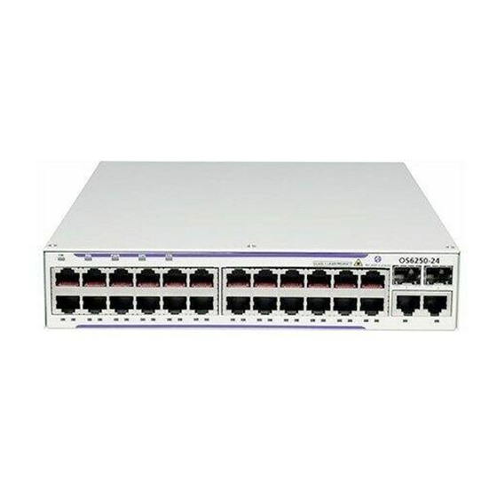
OmniSwitch 6250-24 OmniSwitch 6250 Chassis and Hardware Components OmniSwitch 6250-24 The front panel of the OS6250-24 chassis contains the following major components: System status LEDs • • (24) Unshared 10/100Base-T ports (2) Combo 10/100/1000Base-T or 100/1000BaseX • • (2) HDMI Stacking Ports Internal AC Power Supply •... - Page 45 OmniSwitch 6250 Chassis and Hardware Components OmniSwitch 6250-24 OmniSwitch 6250-24 Front Panel OS6250-24 Front Panel Item Description System Status LEDs Provides status on hardware, software, primary and redundant power. 10/100/1000BaseT or 100/1000BaseX SFP Combo Ports Two 10/100/1000BaseT or SFP combo ports for various supported SFP transceivers.
-
Page 46: Omniswitch 6250-24 Rear Panel
OmniSwitch 6250-24 OmniSwitch 6250 Chassis and Hardware Components OmniSwitch 6250-24 Rear Panel Note. The figure shows a pre-production version of the chassis without product, safety, and compliance information labels. All production versions of the chassis have these labels. OS6250-24 Rear Panel... - Page 47 OmniSwitch 6250 Chassis and Hardware Components OmniSwitch 6250-24 OS6250-24 Specifications Total unshared 10/100BaseT 24 (1-24) ports per switch Total combo ports per switch 2 (25-26) Total HDMI ports per switch 2 (Stack A, Stack B) Total 802.3af PoE ports per...
-
Page 48: Omniswitch 6250-P24
OmniSwitch 6250-P24 OmniSwitch 6250 Chassis and Hardware Components OmniSwitch 6250-P24 The front panel of the OS6250-P24 chassis contains the following major components: System status LEDs • • (24) Unshared 10/100Base-T PoE (802.3at first 6 ports and combo, 802.3af remaining ports) ports (2) Combo 10/100/1000Base-T or 100/1000BaseX •... - Page 49 OmniSwitch 6250 Chassis and Hardware Components OmniSwitch 6250-P24 OmniSwitch 6250-P24 Front Panel OS6250-P24 Front Panel - Update Item Description System Status LEDs Provides status on hardware, software, primary and redundant power. 10/100/1000BaseT or 100/1000BaseX SFP Combo Ports Two 10/100/1000BaseT or SFP combo ports for various supported SFP transceivers.
-
Page 50: Omniswitch 6250-P24 Rear Panel
OmniSwitch 6250-P24 OmniSwitch 6250 Chassis and Hardware Components OmniSwitch 6250-P24 Rear Panel Note. The figure shows a pre-production version of the chassis without product, safety, and compliance information labels. All production versions of the chassis have these labels. OS6250-P24 Rear Panel... - Page 51 OmniSwitch 6250 Chassis and Hardware Components OmniSwitch 6250-P24 OS6250-P24 Specifications Total unshared 10/100BaseT 24 (1-24) ports per switch Total combo ports per switch 2 (25-26) Total HDMI ports per switch 2 (StackA, StackB) Total 802.3at PoE ports per 8 (1-6, 25-26) Ports 25 and 26 share PoE with 23 and 24. Only one set switch of ports can have PoE operational at a time.
-
Page 52: Led Status
OmniSwitch 6250-P24 OmniSwitch 6250 Chassis and Hardware Components LED Status State Description Solid Green Normal Operation. Blinking Green Boot up/Remote Config Load in Progress Solid Amber Operating Temperature Exceeded. Solid Green Primary unit in a stack or standalone switch. Solid Amber Secondary unit in a stack. -
Page 53: Os6250 - Power Supplies
OmniSwitch 6250 Chassis and Hardware Components OS6250 - Power Supplies OS6250 - Power Supplies Internal 30W AC System Power Supply (see “Internal AC Power Supply” on page 3-22) • Internal 30W DC System Power Supply (see “Internal DC Power Supply” on page 3-23) •... -
Page 54: Internal Ac Power Supply
OS6250 - Power Supplies OmniSwitch 6250 Chassis and Hardware Components Internal AC Power Supply Provides system power for the OmniSwitch 6250 switches. P/S Component Description Model Internal AC Power Supply Provides System Power For OS6250-8M/24/24M Input Voltage Range 100-240 VAC... -
Page 55: Internal Dc Power Supply
OmniSwitch 6250 Chassis and Hardware Components OS6250 - Power Supplies Internal DC Power Supply Provides system power for the OmniSwitch 6250 switches. P/S Component Description Model Internal DC Power Supply Provides System Power For OS6250-24MD Input Voltage Range -40 to -60VDC Input Current 2.0 A... -
Page 56: Ps-42W-Ac Power Brick
OS6250 - Power Supplies OmniSwitch 6250 Chassis and Hardware Components PS-42W-AC Power Brick Provides system power and can be installed as a redundant system power supply. 42W, AC Power Brick P/S Component Description Model PS-42W-AC Provides Redundant System OS6250-24/24M/24MD Power For... -
Page 57: Ps-30W-Dc Power Brick
OmniSwitch 6250 Chassis and Hardware Components OS6250 - Power Supplies PS-30W-DC Power Brick Povides system power and can be installed as a redundant system power supply. 30W, 24/-48VDC System Power Brick P/S Component Description Model PS-30W-DC Provides Redundant System OS6250-24/24M/24MD... -
Page 58: Ps-225W-Ac-P Poe Power Supply Module
OS6250 - Power Supplies OmniSwitch 6250 Chassis and Hardware Components PS-225W-AC-P PoE Power Supply Module Provides system and Power over Ethernet and can be installed as either the primary or backup power supply. 225W, -54.5VDC PoE Power Brick P/S Component... -
Page 59: Power Supply Tray
OS6250 - Power Supplies Power Supply Tray Alcatel-Lucent requires the use of the power supply tray when connecting external power supplies. The shelf can be attached directly to the back or side of the chassis and rack mounted. OS6250 Power Supply Shelf... -
Page 60: Ac Power Cords
AC Power Cords OmniSwitch 6250 Chassis and Hardware Components AC Power Cords Since the power cord is the switch’s only disconnect device, it should be plugged into an easily accessible outlet. In the event that your power cord is lost or damaged, refer to the specifications below. -
Page 61: Dc Power Specifications
OmniSwitch 6250 Chassis and Hardware Components DC Power Specifications DC Power Specifications OS6250-24MD Internal DC Power Supply The internal DC power supply has the following additional considerations. Refer to the installation steps described in “OS6250-24MD Internal DC Power Supply Connections” on page 4-27 •... -
Page 62: Stacking Cables
Stacking Cables OmniSwitch 6250 Chassis and Hardware Components Stacking Cables The following cables and transceivers can used for stacking switches into a virtual chassis. Depending on the length and stacking requirements, either copper or fiber can be used. Enterprise models support two HDMI stacking ports and Metro models support two SFP+ stacking ports for use with SFP+ direct attached copper cables. -
Page 63: Console Port
OmniSwitch 6250 Chassis and Hardware Components Console Port Console Port The console port, located on the chassis front panel, provides a console connection to the switch and is required when logging into the switch for the first time. By default, this RJ-45 connector provides a DTE console connection. -
Page 64: Port Pinouts
Port Pinouts OmniSwitch 6250 Chassis and Hardware Components Port Pinouts RJ-45 Console Port – Connector Pinout Pin Number Signals as DTE Console Port Ground Ground 10/100 Ethernet Port – RJ-45 Pinout (non-PoE) Pin Number Description not used not used not used not used Gigabit Ethernet Port –... -
Page 65: 10/100/1000 Mbps Power Over Ethernet Port - Rj-45 Pinout
TX- (+VDC) Overtemp Condition The OmniSwitch 6250 is designed to operate within a specified operating temperature as noted under the specifications section. However, in the event that the normal operating temperature of the switch is exceeded, the following will occur: Upon crossing the configured Upper Threshold, a trap will be sent. -
Page 66: Dying Gasp
Dying Gasp OmniSwitch 6250 Chassis and Hardware Components Dying Gasp If the switch loses all power it will maintain power long enough to send a Dying Gasp message before completely shutting down. An SNMP trap, Syslog message and Link OAM PDUs will be generated. -
Page 67: Link Oam Pdu
OmniSwitch 6250 Chassis and Hardware Components Dying Gasp Link OAM PDU As soon as the power failure is detected an 802.3ah OAM Information PDU is sent to all ports for which link OAM is enabled and the LinkOAM port status is operational. The PDU will have the Dying Gasp bit set. - Page 68 Dying Gasp OmniSwitch 6250 Chassis and Hardware Components page 3-36 OmniSwitch 6250 Hardware Users Guide September 2015...
-
Page 69: Chapter 4 Mounting Os6250 Switches
Static discharge can damage the switch and the backup power supply. Chassis Components OmniSwitch 6250 switches ship with all mounting brackets attached. The following diagram shows the individual chassis and power supply tray components. OS6250 CHASSIS... -
Page 70: Available Mounting Kits
Hardware to mount the rear of two 6250 units in a 19" rack. OS6250-WALL-MNT Wall mounting kit for OS6250-8M only. Contains universal mounting brack- ets and screws for wall mounting an OS6250-8M. page 4-2 OmniSwitch 6250 Hardware Users Guide September 2015... -
Page 71: General Installation Recommendations
Fans pull air into the left side. Air is vented through the right side and rear of the chassis. See table below for recommended clearance above the chassis. Airflow Through Chassis - PoE Model OmniSwitch 6250 Hardware Users Guide September 2015 page 4-3... -
Page 72: Recommended Clearances
Reliable Earthing Reliable earthing of rack-mount equipment should be maintained. Particular attention should be given to supply connections other than direct connections to the branch circuit (e.g. use of power strips). page 4-4 OmniSwitch 6250 Hardware Users Guide September 2015... -
Page 73: Power Supply Information
Power Supply Information Power Supply Information Before getting started, please note that OmniSwitch 6250 power supplies can be installed in a number of different configurations. For example: Non-redundant system power - Provides power requirements to the chassis, with no power supply •... -
Page 74: Assembling Os6250 Switches
A chassis and power supply tray can be assembled side-by-side to fit into a standard 19-inch rack mount as show in the figure below. Rear center mounting bracket. Front center mounting brackets. Fully Assembled Chassis and Power Supply Tray (OS6250-RM-19) page 4-6 OmniSwitch 6250 Hardware Users Guide September 2015... - Page 75 Attach the slot-brackets to the front and rear of the chassis using the attachment screws (M3 flathead) provided for each bracket. Slot-Bracket Attachment Attach slide-bracket to front of the power supply tray using the attachment screws (M3 flathead). Slide bracket Slide-Bracket Attachment OmniSwitch 6250 Hardware Users Guide September 2015 page 4-7...
- Page 76 Power Supply Tray Extension Bracket Slide the power supply tray and chassis together. Slide the power supply tray extension into slot-bracket on chassis. Power Supply Tray Extension Bracket with Slide Bracket page 4-8 OmniSwitch 6250 Hardware Users Guide September 2015...
- Page 77 Place bracket plate over the front brackets and secure with thumb screws. Secure power supply tray to chassis with bracket plate and captive thumb screws. Secure Front Bracket with Plate Skip to “Securing Power Supplies in Power Supply Tray” on page 4-13 OmniSwitch 6250 Hardware Users Guide September 2015 page 4-9...
- Page 78 Fully Assembled Side-by-Side Chassis Assembly (OS6250-DUAL-MNT) Attach the slot-brackets and slide-brackets to the front and back of the chassis using the attachment screws (M3 flat head) provided for each bracket. Attach Slot/Slide-Brackets page 4-10 OmniSwitch 6250 Hardware Users Guide September 2015...
- Page 79 Align the chassis and slide both front and rear center brackets together. Slide chassis together Slide Chassis Together Place bracket plate over front and rear brackets and secure with thumb screws. Bracket Plate and Screws Secure Front and Back with Bracket Plate OmniSwitch 6250 Hardware Users Guide September 2015 page 4-11...
-
Page 80: Attaching Power Supply Tray To Rear Of Chassis
Be sure that the two holes in the tray are aligned with the threaded holes in the rear panel of the chassis and secure the tray to the switch using the two attachment screws (M3 pan head). Skip to “Securing Power Supplies in Power Supply Tray” on page 4-13 page 4-12 OmniSwitch 6250 Hardware Users Guide September 2015... -
Page 81: Securing Power Supplies In Power Supply Tray
Place Power Supply Into Tray Position the power supply bracket over the power supply ensuring the tabs are placed over the power supply holding it in place. Power Supply Bracket Tabs Power Supply Bracket OmniSwitch 6250 Hardware Users Guide September 2015 page 4-13... -
Page 82: Power Supply Module Installation
Captve Screw Tab Slots Securing Power Supply Module in Tray Secure the power supply to the power supply tray using the captive thumb screw. page 4-14 OmniSwitch 6250 Hardware Users Guide September 2015... -
Page 83: Mounting Os6250 Switches
• chassis and position it on the rack, and a second person to secure the chassis to the rack using attachment screws. (Please note that Alcatel-Lucent does not provide rack-mount screws. Use the screws supplied by the rack vendor.) •... - Page 84 Be sure to install the screws in the bottom hole of each flange, as shown, before proceeding. Once the screws at the bottom of each flange are secure, install the remaining two rack mount screws. Be sure that all screws are securely tightened. page 4-16 OmniSwitch 6250 Hardware Users Guide September 2015...
-
Page 85: Power Supply Tray - Removeable Section
• Remove the three top screws and the two side screws and slide removal section out. Top Screws Side Screws Stacked Chassis - Power Supply Tray Section Removed OmniSwitch 6250 Hardware Users Guide September 2015 page 4-17... -
Page 86: Os6250-Rm-19-L - Mounting Instructions
Mounting OS6250 Switches Mounting OS6250 Switches OS6250-RM-19-L - Mounting Instructions A single chassis can be mounted into a standard 19-inch rack as shown in the figure below.. L-Bracket OS6250-RM-19-L page 4-18 OmniSwitch 6250 Hardware Users Guide September 2015... -
Page 87: Os6250-Rear-Mnt - Mounting Instructions
Mounting OS6250 Switches Mounting OS6250 Switches OS6250-REAR-MNT - Mounting Instructions Alcatel-Lucent provides an optional rack mounting kit that allows OmniSwitches to be secured to both the front and back rails of the rack for additional stability. Parts Provided Slot/Slide Brackets (30) M3 (6) M2.6... -
Page 88: Completed Assembly
Mounting OS6250 Switches Mounting OS6250 Switches Completed Assembly Extension Bracket Flanged Rack Mount Insert Power Supply Tray Insert Power Supply Tray Brackets Extension Bracket Flanged Rack Mount Insert OS6250-REAR-MNT page 4-20 OmniSwitch 6250 Hardware Users Guide September 2015... -
Page 89: General Table-Mounting Guidelines
Table-Mounting OS6250 Switches General Table-Mounting Guidelines OmniSwitch 6250 switches can be installed freestanding as tabletop-mounted units. If you will be table- mounting your switch(es), refer to the important guidelines below before installing. When choosing a location for the switch, be sure that adequate clearance has been provided for chassis •... - Page 90 Do not over- tighten. Otherwise, the switch/power supply tray assembly may simply be placed on the table surface with- out attachment screws. Table Mounted Chassis page 4-22 OmniSwitch 6250 Hardware Users Guide September 2015...
-
Page 91: Wall-Mounting The Os6250-8M
(i.e., grounded outlet). Refer to the guidelines listed below for additional details. The power cord for OmniSwitch 6250 switches measures two (2) meters (approximately 6.5 feet) in •... -
Page 92: Os6250-Wall-Mnt - Wall-Mounting Installation
NOTE: For wall mounting, it is recommended that the chassis assembly is oriented sideways, with the chassis front panel facing left, as shown in the diagram below. Recommended Wall Mount Chassis Orientation (OS6250-WALL-MNT) page 4-24 OmniSwitch 6250 Hardware Users Guide September 2015... - Page 93 Be sure to use fasteners that are approved for the full weight of the chassis assembly. Consult fastener specifications for full details. Secure the unit to the wall using appropriate wall fasteners. OmniSwitch 6250 Hardware Users Guide September 2015 page 4-25...
-
Page 94: Connecting Chassis To Power Source
Insert two screws (provided) into the retainer clip slots and tighten until secure. Retainer bracket Slotted retainer clip Secured Power Cord Connect primary and optional redundant power supplies to AC power source. Monitor the chassis as it boots. page 4-26 OmniSwitch 6250 Hardware Users Guide September 2015... -
Page 95: Os6250-24Md Internal Dc Power Supply Connections
HALF TURN PER .75 Twisted pair wire (red and black) for a DC power supply Note. Refer to the wiring diagram for information on connecting the DC power supply to a DC power source. OmniSwitch 6250 Hardware Users Guide September 2015 page 4-27... -
Page 96: Securing The Redundant Dc Power Supply Connector
Connect the male DC connector to the female connector and secure to the female DC connector with the captive screws contained in the male DC connector. Female DC Connector Male DC Connector Secure female connector to bracket with screws Secure DC Power Connector Bracket page 4-28 OmniSwitch 6250 Hardware Users Guide September 2015... -
Page 97: Installing Dc Power Source Wire Leads
DC power connector as a guide to positive, negative, and ground connections. If the wire leads are plugged into the wrong holes, the power supply will not work properly and damage to the unit may result. OmniSwitch 6250 Hardware Users Guide September 2015 page 4-29... - Page 98 -48V, +48V, or -60V. Repeat Steps 2 through 4 for the remaining positive and negative wire leads. OS6250 Power Supply DC Power Source Correct Polarity Connections page 4-30 OmniSwitch 6250 Hardware Users Guide September 2015...
-
Page 99: Hot-Swapping Power Supplies
Install the new power supply by following the installation steps beginning at step 3 on page 4-13 of this chapter. OmniSwitch 6250 Hardware Users Guide September 2015 page 4-31... - Page 100 Connecting Chassis to Power Source Mounting OS6250 Switches page 4-32 OmniSwitch 6250 Hardware Users Guide September 2015...
-
Page 101: Booting 6250 Switches
Booting an OmniSwitch 6250 The OmniSwitch 6250 switch does not use an on/off switch. The power cord is the switch’s only connect/ disconnect device. The power connector socket is located on the power supply rear panel. For more infor- mation, refer to “OmniSwitch 6250 Chassis and Hardware Components”... -
Page 102: Console Port
To change the data bits (i.e., word size) value, enter boot serialwordsize, followed by the number of data bits. Options include 7 and 8 (default). For example: Boot > boot serialwordsize 7 page 5-2 OmniSwitch 6250 Hardware Users Guide September 2015... - Page 103 To save changes to the boot.params file, refer to step 7. Return to the CLI prompt by entering exit at the boot prompt. OmniSwitch 6250 Hardware Users Guide September 2015...
-
Page 104: Viewing The Power Supply Status
(optional) unexpectedly shuts down, the switch sends out a notification to the user. In addition, the power LED on the chassis front panel displays solid amber. Note. For detailed OmniSwitch 6250 LED information, refer to “LED Status” on page 3-20. -
Page 105: Monitoring The Chassis
Monitoring the Chassis Monitoring the Chassis OmniSwitch 6250 switches can be monitored and managed via the console port using Command Line Interface (CLI) commands. The switches can also be monitored and managed via the Ethernet using CLI commands, WebView, SNMP, and OmniVista. -
Page 106: Checking The Fan Status
Running For a complete list of output definitions for this command, refer to the OmniSwitch CLI Reference Guide. Checking the Power Supply Status For information on checking power supplies for OmniSwitch 6250 switches, refer to “Booting 6250 Switches” on page 5-1. -
Page 107: Using Leds To Visually Monitor The Chassis
Booting 6250 Switches Monitoring the Chassis Using LEDs to Visually Monitor the Chassis The front and rear panel of OmniSwitch 6250 switches provides status LEDs that are useful in visually monitoring the status of the switches. LEDs include: Ethernet Port LEDs •... - Page 108 Monitoring the Chassis Booting 6250 Switches page 5-8 OmniSwitch 6250 Hardware Users Guide September 2015...
-
Page 109: Managing Power Over Ethernet (Poe)
6 Managing Power over Ethernet (PoE) Power over Ethernet (PoE) is supported on OmniSwitch 6250 switches and provides inline power directly from the switch’s Ethernet ports. Powered Devices (PDs) such as IP phones and wireless APs can be powered directly from the switch’s RJ-45 ports. -
Page 110: In This Chapter
Note. You can also monitor all chassis components and manage many chassis features, including Power over Ethernet, with WebView, Alcatel-Lucent’s embedded web-based device management application. WebView is an interactive and easy-to-use GUI that can be launched from the OmniVista or a web browser. -
Page 111: Power Over Ethernet Specifications
Managing Power over Ethernet (PoE) Power over Ethernet Specifications Power over Ethernet Specifications The table below lists general specifications for Alcatel-Lucent’s Power over Ethernet support. For more detailed power supply and Power Source Equipment (PSE) specifications, refer to Chapter 3, “OmniSwitch 6250 Chassis and Hardware Components.”... -
Page 112: Viewing Poe Power Supply Status
-> show power Slot Wattage Type Status Location ----+----+---------+------+-----------+---------- External External External External For detailed information on the show power command output, refer to the CLI Command Reference Guide. page 6-4 OmniSwitch 6250 Hardware Users Guide September 2015... -
Page 113: Configuring Power Over Ethernet Parameters
Note. You cannot use the slot/port syntax to initially activate PoE on a port. This syntax is intended only to reactivate power to those that have been disconnected via the lanpower stop command. To initially activate PoE, you must use the lanpower start slot syntax only, as described above. OmniSwitch 6250 Hardware Users Guide September 2015 page 6-5... -
Page 114: Configuring The Total Power Available To A Port
Increasing the total power available to a switch may provide more demanding Powered Devices (PDs) with additional power required for operation. Decreasing the total power available helps preserve inline power and assists in the overall management of the switch’s power budget. page 6-6 OmniSwitch 6250 Hardware Users Guide September 2015... -
Page 115: Setting Port Priority Levels
1 to the highest priority level of critical. Now that the default value has been reconfigured, this port should be reserved for those PDs that are mission critical for network opera- tions. OmniSwitch 6250 Hardware Users Guide September 2015 page 6-7... -
Page 116: Understanding Priority Disconnect
To enable priority disconnect, use the lanpower priority-disconnect command. Be sure to specify the slot number in the command line. For example, the syntax -> lanpower 1 priority-disconnect enable enables priority disconnect on slot 1. page 6-8 OmniSwitch 6250 Hardware Users Guide September 2015... - Page 117 OmniSwitch 6250 Hardware Users Guide September 2015 page 6-9...
-
Page 118: Priority Disconnect Is Disabled
When priority disconnect is disabled, power will be denied to any incoming PD, regardless of its port priority status (i.e., low, high, and critical) or physical port number (i.e., 1/1). page 6-10 OmniSwitch 6250 Hardware Users Guide September 2015... -
Page 119: Monitoring Power Over Ethernet Via Cli
Undefined None 31000 Undefined None Slot 1 Max Watts 225 1 Power Supplies Available Note. For detailed information on show lanpower command output, refer to the OmniSwitch CLI Refer- ence Guide. OmniSwitch 6250 Hardware Users Guide September 2015 page 6-11... - Page 120 Monitoring Power over Ethernet via CLI Managing Power over Ethernet (PoE) page 6-12 OmniSwitch 6250 Hardware Users Guide September 2015...
-
Page 121: Managing Omniswitch 6250 Stacks
7 Managing OmniSwitch 6250 Stacks In addition to their working as individual stand-alone switches, OmniSwitch 6250 switches can also be linked together to work as a single virtual chassis known as a stack. With stacks, users can easily expand their switching capacity simply by adding additional switches to the stack. In addition, stacks provide enhanced resiliency and redundancy features. -
Page 122: In This Chapter
In This Chapter Managing OmniSwitch 6250 Stacks In This Chapter This chapter provides information on OmniSwitch 6250 switches configured to operate as a single virtual chassis. Topics described in the chapter include: OmniSwitch 6250 stack overview on page 7-4. •... -
Page 123: Omniswitch 6250 Stacking Specifications
Changing Stacking Mode on Metro Models The OmniSwitch 6250 Metro Models non-combo fiber ports can be set to either stackable or standalone mode. By default the mode is set to standalone but can be changed in order to support stacking. After changing the mode the switch must be rebooted. -
Page 124: Omniswitch 6250 Stack Overview
Managing OmniSwitch 6250 Stacks OmniSwitch 6250 Stack Overview Users can configure OmniSwitch 6250 switches into a single virtual chassis known as a stack. With stacks, switching capacity can be easily expanded simply by adding additional switches to the stack. For exam- ple, a user can start with a stack composed of two switches and add additional switches to that stack as network demands increase over time. - Page 125 “Synchronizing Switches in a Stack” on page 7-37 for more information. Primary A stack of four OmniSwitch 6250 switches is operating normally. The stack consists of a primary module, sec- Secondary ondary module, and two elements operating in idle sta- Idle tus.
- Page 126 Roles Within the Stack Managing OmniSwitch 6250 Stacks A stack of two OmniSwitch 6250 switches is operating normally. The stack consists of a primary module and a Primary secondary module. (The software on both elements in the stack is synchronized.)
-
Page 127: Primary Management Module Selection
Roles Within the Stack Primary Management Module Selection For a stack of OmniSwitch 6250 switches to operate as a virtual chassis, there must be a mechanism for dynamically selecting the switch within the stack that will assume the primary management role. OmniS- witch 6250 switches use three different methods for selecting the primary switch. - Page 128 For more information on using saved slot information to determine the primary switch in a stack, refer to the diagram below: Saved Slot 6 Four OmniSwitch 6250 switches are stacked; all switches are Saved Slot 5 connected via stacking cables. The user configures each switch to have a unique saved slot number.
- Page 129 For more information on using saved slot information to determine the primary switch in a stack, refer to the diagram below: Four OmniSwitch 6250 switches are stacked and connected via stacking cables. All switches are currently powered off. The user powers on a sin- gle switch in the stack.
-
Page 130: Secondary Management Module Selection
Managing OmniSwitch 6250 Stacks Secondary Management Module Selection In order to provide effective management module redundancy, all OmniSwitch 6250 stacked configura- tions dynamically assign a backup, or secondary, management module during the boot process. OmniS- witch 6250 stacks use two different methods for selecting the secondary switch. These methods are: Stacking connection to the primary switch •... - Page 131 For more information on using saved slot information to determine the secondary management module in a stack, refer to the diagram below: Saved Slot 1 Four OmniSwitch 6250 switches are stacked; all switches are con- Saved Slot 3 nected via stacking cables. The user configures each switch to have a unique saved slot number, as shown.
-
Page 132: Idle Module Role
For more information on dynamic assignment of idle modules in a stack, refer to the diagram below: Four OmniSwitch 6250 switches are stacked; all switches are con- nected via stacking cables. The stack is booted. -
Page 133: Pass-Through Mode
MAC address will be given the secondary manage- ment role. The slot with the higher MAC address will be forced into the pass-through mode. OmniSwitch 6250 Hardware Users Guide September 2015... -
Page 134: Recovering From Pass-Through Mode (Duplicate Slot Numbers)
This can be further verified by looking down the saved slot column in the table. Note that slot 2, operating in the secondary management role, has a saved slot value of 2. Slot 1001, operating in pass-through, also has a saved slot value of 2. page 7-14 OmniSwitch 6250 Hardware Users Guide September 2015... - Page 135 State Saved Link A Remote Remote Link B Remote Remote Slot State Port State Port ----+-----------+--------+------+-------+-------+-------+-------+-------+------- 1 PRIMARY RUNNING StackA StackA 2 SECONDARY RUNNING StackB StackB 3 IDLE RUNNING StackA StackB OmniSwitch 6250 Hardware Users Guide September 2015 page 7-15...
- Page 136 StackA 3 IDLE RUNNING StackB StackA 4 IDLE RUNNING StackB StackA 5 IDLE RUNNING StackB StackA 6 IDLE RUNNING StackB StackA 7 IDLE RUNNING StackB StackA 8 IDLE RUNNING StackB StackA page 7-16 OmniSwitch 6250 Hardware Users Guide September 2015...
-
Page 137: Stack Cabling
Stacking cables for OmniSwitch 6250 switches must be connected in an A-B pattern. In other words, the cable connected to stacking port A of one switch must be connected to stacking port B of the adjacent switch. -
Page 138: Redundant Stacking Cable Connection
Managing OmniSwitch 6250 Stacks Redundant Stacking Cable Connection OmniSwitch 6250 switches allow redundant stacking cable connections between the top-most and bottom- most switches in a stack. Important. For a stacked configuration to have effective redundancy, a redundant stacking cable must be installed between the upper-most and bottom-most switch in the chassis at all times. -
Page 139: Checking Redundant Stacking Cable Status
For example: -> show stack status Redundant cable status : present In this example, a redundant stacking cable connection is present between the top-most and bottom-most switches in the stack. OmniSwitch 6250 Hardware Users Guide September 2015 page 7-19... -
Page 140: Slot Numbering
Managing OmniSwitch 6250 Stacks Slot Numbering For a stack of OmniSwitch 6250 switches to operate as a virtual chassis, each module in the stack must be assigned a unique slot number. To view the current slot assignments for a stack, use the... -
Page 141: Dynamic Slot Number Assignment
4, and so on. When the bottom of the stack is reached, the slot numbering sequence resumes at the top of the stack, as shown. This helps ensure a more ordered and manageable stack topology. Dynamic Slot Numbering Example 1 OmniSwitch 6250 Hardware Users Guide September 2015 page 7-21... - Page 142 3 is assigned the slot number 4, and so on. This default procedure ensures the most ordered and manageable stack topology out of the box. Dynamic Slot Numbering Example 2 page 7-22 OmniSwitch 6250 Hardware Users Guide September 2015...
-
Page 143: Manual Slot Number Assignment
Instead, new slot number information is first saved to each boot.slot.cfg file across the stack. The reboot is saved for last in order to avoid duplicate slot numbers within the stack, which would cause unwanted pass-though mode conditions (see page 7-13). OmniSwitch 6250 Hardware Users Guide September 2015 page 7-23... -
Page 144: Reverting To The Dynamic Slot Numbering Model
Because the system software no longer has preassigned slot infor- mation to read during the boot process, the stack uses the dynamic slot number assignment method described on page 7-21. page 7-24 OmniSwitch 6250 Hardware Users Guide September 2015... -
Page 145: Hot-Swapping Modules In A Stack
Hot-Swapping Modules In a Stack Hot-Swapping Modules In a Stack As with chassis-based switches, NI modules within an OmniSwitch 6250 virtual chassis are hot-swappa- ble. NI modules are essentially those modules operating in the stack in idle mode. These modules can be removed from, or added to, an existing stack without disrupting other modules in the stack. -
Page 146: Merging Stacks
For information on stack cabling, refer to page 7-17. Power on all incoming modules. Note. No more than eight switches can operate in a single stacked configuration at any time. page 7-26 OmniSwitch 6250 Hardware Users Guide September 2015... -
Page 147: Reloading Switches
OmniS- witch CLI Reference Guide. Primary - Slot 1 In this stack of four OmniSwitch 6250 switches, the slot 1 switch Secondary - Slot 2 is the primary management module. The slot 2 switch is the sec- ondary. - Page 148 If there are only two switches in the stack, the switch that was reloaded (the former primary) assumes the secondary role when it comes back up. In this stack of two OmniSwitch 6250 switches, the slot 1 switch Primary - Slot 1 is the primary management module.
-
Page 149: Reloading The Secondary Management Module
OmniS- witch CLI Reference Guide. Primary - Slot 1 In this stack of four OmniSwitch 6250 switches, the slot 1 switch Secondary - Slot 2 is the primary management module. The slot 2 switch is the sec- ondary. - Page 150 If there are only two switches in the stack, the switch that was reloaded (the former secondary) resumes the secondary role when it comes back up. In this stack of two OmniSwitch 6250 switches, the slot 1 switch Primary - Slot 1 is the primary management module.
-
Page 151: Reloading Switches With Idle Roles
Otherwise, the switch is likely to come up again in pass-through mode. For detailed information, including steps used to recover from pass-through, refer to page 7-13. OmniSwitch 6250 Hardware Users Guide September 2015 page 7-31... -
Page 152: Reloading All Switches In A Stack
All other switches will be assigned to idle roles. An illustrated example of this method for assigning slot numbers and management roles is provided on pages 7-23 and 7-24. page 7-32 OmniSwitch 6250 Hardware Users Guide September 2015... - Page 153 To check the current saved slot information across the stack, use the show stack topology command. For detailed information on pass-through mode, refer to “Pass-Through Mode” on page 7-13. OmniSwitch 6250 Hardware Users Guide September 2015 page 7-33...
-
Page 154: Avoiding Split Stacks
For more information on the redundant stacking cable connection, refer to page 7-18. For information on detecting a stack split with Stack Split Protection (SSP), refer to page 7-38. page 7-34 OmniSwitch 6250 Hardware Users Guide September 2015... -
Page 155: Changing The Secondary Module To Primary
Changing the Secondary Module to Primary OmniSwitch 6250 stacks allow users to manually force the secondary switch to assume the primary management role. This is referred to as “takeover.” The behavior of a takeover is similar to that of reload-... - Page 156 If there are only two switches in the stack, the former primary switch resumes the secondary role when it comes back up following the takeover. In this stack of two OmniSwitch 6250 switches, the slot 1 switch Primary - Slot 1 is the primary management module.
-
Page 157: Synchronizing Switches In A Stack
“Reloading All Switches in a Stack” on page 7-32. Note. For more information on management module synchronization and managing the /flash/working and /flash/certified directories, refer to the “Managing CMM Directory Content” chapter in the Switch Management Guide. OmniSwitch 6250 Hardware Users Guide September 2015 page 7-37... -
Page 158: Stack Split Detection (Ssp)
MAC and IP addresses and network disrup- tion. • Guard Timer - A configurable timer determining how long a unit will wait before beginning to send SSP PDUs after a stack recovery. page 7-38 OmniSwitch 6250 Hardware Users Guide September 2015... -
Page 159: Basic Operation
After the re-boot the administrator has to manually recover the switch by first disabling SSP and then re-enabling SSP. This clears the protection state variables stored in the EEPROM/boot.params. OmniSwitch 6250 Hardware Users Guide September 2015 page 7-39... - Page 160 3. Automatic Recovery - After guard-timer expiration, Primary will bring up elements one at a time. 4. Once stack is functioning, Primary will send trap indicating stack recovery. Stack Split Example page 7-40 OmniSwitch 6250 Hardware Users Guide September 2015...
-
Page 161: Monitoring The Stack
This command displays all the information related to SSP when enabled. show stack split-protection statistics This command shows statistics of stack split-protection. show stack split-protection stacking- This command shows the SSP state of all stacked units. units OmniSwitch 6250 Hardware Users Guide September 2015 page 7-41... -
Page 162: Visually Monitoring The Stack
Users can also monitor many stack operations by viewing the front panel LEDs on all elements in the stack. Refer to “LED Status” on page 3-20 for detailed information on LEDs and stack status. page 7-42 OmniSwitch 6250 Hardware Users Guide September 2015... -
Page 163: Regulatory Compliance And Safety Information
Español: Este equipo cumple los requisitos esenciales y otras disposiciones de las directivas 2004/108/CE (EMC), 2006/95/CE (LVD), 91/263/CEE (equipos terminales de telecomunicación, si procede), 1999/5/ CE (R&TTE, si procede). OmniSwitch 6250 Hardware Users Guide September 2015 page A-1... -
Page 164: China Rohs: Hazardous Substance Table
对销售之日的所售产品,本表显示, 阿尔卡特朗讯公司供应链的电子信息产品可能包含这些物质。注意:在所售产 品中可能会也可能不会含有所有所列的部件。 This table shows where these substances may be found in the supply chain of Alcatel-Lucent electronic information products, as of the date of sale of the enclosed product. Note that some of the component types listed above may or may not be a part of the enclosed product. -
Page 165: California Proposition 65 Warning
Corrugated Cardboard Corrugated Fiberboard Low-Density Polyethylene California Proposition 65 Warning WARNING: This product contains chemicals known to the State of California to cause cancer and birth defects or other reproductive harm. OmniSwitch 6250 Hardware Users Guide September 2015 page A-3... -
Page 166: Waste Electrical And Electronic Equipment (Weee) Statement
Switzerland and therefore marked with the symbol: Treatment applied at end of life of the product in these countries shall comply with the applicable national laws implementing directive 2002/96EC on waste electrical and electronic equipment (WEEE). page A-4 OmniSwitch 6250 Hardware Users Guide September 2015... -
Page 167: Standards Compliance
• • EN 61000-3-3 EN 61000-4-2 • • EN 61000-4-3 EN 61000-4-4 • EN 61000-4-5 • EN 61000-4-6 • EN 61000-4-8 • • EN 61000-4-11 EN 61000-6-2 • • EN 61000-6-4 OmniSwitch 6250 Hardware Users Guide September 2015 page A-5... -
Page 168: Canada Class A Statement
CISPR22 Class A warning This is a Class A product. In a domestic environment, this product may cause radio interference. Under such circumstances, the user may be requested to take appropriate countermeasures. page A-6 OmniSwitch 6250 Hardware Users Guide September 2015... -
Page 169: Korean Emission Statement
This is a Class A Information Product. When used in a residential environment, it may cause radio frequency interference. Under such circumstances, the user may be requested to take appropriate counter- measure. OmniSwitch 6250 Hardware Users Guide September 2015 page A-7... -
Page 170: Network Cable Installation Warning
Installationen, Wartungen oder Konfigurationen vorge- nommen werden. Español: Para evitar peligro de descargas, no conecte o desconecte ningun cable, ni realice ninguna insta- lación, maintenimiento o reconfiguración de este producto durante una tormenta eléctrica. page A-8 OmniSwitch 6250 Hardware Users Guide September 2015... -
Page 171: Installation Warning
Netzverbindungen getrennt sind bevor das Gerät gewartet oder bewegt wird. Español: Antes de empezar a trabajar con un sistema, asegurese que el interruptor está cerrado y el cable eléctrico desconectado. OmniSwitch 6250 Hardware Users Guide September 2015 page A-9... -
Page 172: Proper Earthing Requirement Warning
• toma de alimentación adecuadamente cableada y con toma de tierra. Cualquier otro equipo a cual se conecte este producto también debe estar conectado a tomas de • alimentación adecuadamente cableadas. page A-10 OmniSwitch 6250 Hardware Users Guide September 2015... -
Page 173: Read Important Safety Information Warning
Español: Este equipo se debe instalar en un sitio con acceso restrinjido. Un sitio con el acceso restrinjido es uno seguro y con acceso limitado al personal de servicio que tiene una clave especial u otros medios de seguridad. OmniSwitch 6250 Hardware Users Guide September 2015 page A-11... -
Page 174: Wrist Strap Warning
Français: L'électricité statique (ESD) peut endommager les composants du commutateur. Pour cette raison Alcatel-Lucent joint à l'envoi du châssis un bracelet antistatique à brancher sur la prise mise à la terre située en bas à droite du commutateur. Vous devrez mettre ce bracelet avant toute intervention hard- ware. -
Page 175: Instrucciones De Seguridad En Español
Deseche las baterías usadas según las instrucciones del fabricante. Las instrucciones del fabricante son como sigue: Devuelva el módulo con la batería del litio a Alcatel-Lucent. La batería del litio será substitu- ida en la fábrica de Alcatel-Lucent. -
Page 176: Advertencia Sobre Una Apropiada Conexión A Tierra
Para que la pulsera antiestática sea eficaz en la eliminación de ESD, las fuentes de alimentación se deben instalar en el chasis y enchufar en las salidas de CA con descarga a tierra. Clase de seguridad Cumple con 21CFR 1040.10 y 1040.11 ó sus equivalentes. page A-14 OmniSwitch 6250 Hardware Users Guide September 2015...