Table of Contents
Advertisement
Quick Links
Advertisement
Table of Contents

Related Manuals for Powermatic 1791291K


Summary of Contents for Powermatic 1791291K
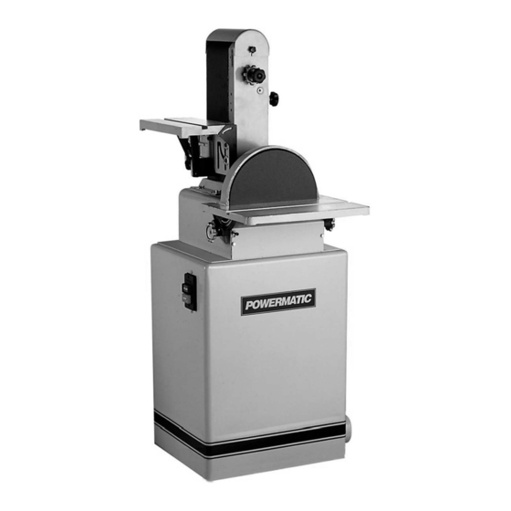
- Page 1 This Manual is Bookmarked Operating Instructions and Parts Manual Combination Belt/Disc Sander Model 31A WMH TOOL GROUP, Inc. 2420 Vantage Drive Elgin, Illinois 60124 Part No. M-0460267 Ph.: 800-274-6848 Revision G1 6/08 www.powermatic.com Copyright © 2008 WMH Tool Group, Inc.
-
Page 2: Warranty And Service
This warranty covers only the initial purchaser of the product. WHAT IS THE PERIOD OF COVERAGE? The general POWERMATIC warranty lasts for the time period specified in the product literature of each product. WHAT IS NOT COVERED? The Five Year Warranty does not cover products used for commercial, industrial or educational purposes. Products with a Five Year Warranty that are used for commercial, industrial or education purposes revert to a One Year Warranty. -
Page 3: Table Of Contents
Extension Cords... 13 Guide to Sanding Belts and Discs... 19 Troubleshooting... 20 Replacement Parts ... 20 Parts List: 31A Sander Body Assembly ... 21 31A Sander Body Assembly... 23 Parts List: 31A Stand Assembly (1PH) ... 24 31A Stand Assembly (1PH)... 25 Parts List: 31A Stand Assembly (3PH) ... -
Page 4: Warning
Make certain the work area is well lighted and that a proper exhaust system is used to minimize dust. Powermatic recommends the use of anti-skid floor strips on the floor area where the operator normally stands and that each machine’s work area be marked off. - Page 5 Misuse. Do not use this Powermatic sander for other than its intended use. If used for other purposes, Powermatic disclaims any real or implied warranty and holds itself harmless for any injury or damage which may result from that use.
-
Page 6: Introduction
Introduction This manual is provided by WMH Tool Group, Inc. covering the safe operation and maintenance procedures for a Powermatic Model 31A Combination Belt/Disc Sander. This manual contains instructions on installation, safety precautions, general operating procedures, maintenance instructions and parts breakdown. -
Page 7: Dimensions
Dimensions Figure 1... -
Page 8: Unpacking
Open shipping container and check for shipping damage. Report any damage immediately to your distributor and shipping agent. Do not discard any shipping material until the Sander is assembled and running properly. Compare the contents of your container with the following parts list to make sure all parts are intact. -
Page 9: Assembly
– part no. 708118 – is available from WMH Tool Group.) 2. The sander is shipped with the belt arm in horizontal position. Pull out on the index pin and raise the arm to vertical position, as shown in Figure 3. -
Page 10: Installing And Tracking Abrasive Belt
2. Remove the side cover by unscrewing the two knobs holding it, and sliding the tabs of the side cover out of the slots of the sander. 3. Loosen the tension knob (C). This will lower the top drum, providing slack for installing the abrasive belt. -
Page 11: Installing Abrasive Disc
Installing Table Refer to Figure 9: 1. On both sides of the sander body, loosen the locking wheels (A), and pull the trunnion holders (B) out far enough to allow clearance between trunnion holders and sander body. -
Page 12: Dust Outlet And Cord Plate
You may either install a UL/CSA listed plug suitable for 230 or 460 volt operation, or “hard- wire” the sander directly to a service panel. If the Sander is to be hard-wired to a panel, make sure a disconnect is available for the operator. -
Page 13: Extension Cords
(Three Phase model only) Extension Cords An extension cord is not recommended; if possible, position your Sander within reach of the power supply. If an extension cord becomes necessary, make sure the cord rating is suitable for the amperage listed on the machine’s motor plate. -
Page 14: Adjustments
Arrow labels are affixed to the sander to indicate these directions. Platen Adjustment The platen should not require attention on your new sander. -
Page 15: Work Stop
90 degrees when the trunnion pointer is at zero. Work Stop Your sander is equipped with a work stop for use with the belt arm in the horizontal position (see Figure 23). When installed, the work stop will prevent a work piece from being thrown from the belt. -
Page 16: Operation
Operation The belt and disc sander can be equipped with a variety of abrasives and grit sizes to handle a wide variety of materials, from soft woods to hardened steel. It can be used to rapidly remove material and produce a mirror finish. Using... -
Page 17: Types Of Operations
The chart on page 19 lists the various grits and materials used and lists the grit symbols. It is generally better to start with a slightly coarser abrasive than would seem practical because it will give faster material removal, generate less heat, and will sand more freely. -
Page 18: Maintenance
Use SAE No. 10 Oil on these: internal threads of table locking wheels (A, Figure 14) belt arm index pin (shown in Figure 3) All bearings used on the Model 31A Sander are sealed for life and require no lubrication. Failure to Figure 25... -
Page 19: Guide To Sanding Belts And Discs
Guide to Sanding Belts and Discs... -
Page 20: Troubleshooting
Replacement parts are listed on the following pages. To order parts or reach our service department, call 1-800-274-6848, Monday through Friday (see our website for business hours, www.powermatic.com). Having the Model Number and Serial Number of your machine available when you call will allow us to serve you quickly and accurately. -
Page 21: Parts List: 31A Sander Body Assembly
Parts List: 31A Sander Body Assembly Index No. Part No. Description Size 1... 31A-1...Cast Base... 1 2... 31A-2...Dust Chute (Disc) ... 1 3... 31A-3...Sanding Disc ... 1 4... 31A-4...Disc Table ... 1 5... 31A-5...Trunnion... 2 ° 6... 31A-6...90 Stop Bracket ... 1 7... - Page 22 58... 31A-52...Lock Washer ...M16... 2 59... 31A-53...Hex Head Flange Bolt...M6 x 20 ... 4 60... 31A-54...Lock Washer ...M6... 2 61... 31A-55...Hex Head Bolt ...M6 x 8 ... 2 62... TS-1504041 ...Socket Head Cap Screw...M8 x 20 ... 2 63... TS-2361081 ...Lock Washer ...M8... 2 64...
-
Page 23: 31A Sander Body Assembly
31A Sander Body Assembly... -
Page 24: Parts List: 31A Stand Assembly (1Ph)
35... 31A-99...Hex Nut ...M10... 2 36... TS-1550071 ...Flat Washer...M10... 2 37... 150527 ...Sponge... 2 38... 998630 ...Strain Relief...7P-2 ... 1 39... 31A-102 ...Warning Label (not shown) ... 1 40... 6823013...Black Stripe (not shown) ... per ft. 41... 3312341...Powermatic Label (not shown) ... 1... -
Page 25: Stand Assembly (1Ph)
31A Stand Assembly (1PH) -
Page 26: Parts List: 31A Stand Assembly (3Ph)
28... 31A-101 ...Spacer Washer... 2 29... 31A-99...Hex Nut ...M10... 2 30... TS-1550071 ...Flat Washer...M10... 2 31... 150527 ...Sponge... 2 32... 31A-102 ...Warning Label (not shown) ... 1 33... 6823013...Black Stripe (not shown) ... per ft. 34... 3312341...Powermatic Label (not shown) ... 1... -
Page 27: Stand Assembly (3Ph)
31A Stand Assembly (3PH) -
Page 28: Electrical Connections (1 Phase)
Electrical Connections (1 Phase) -
Page 29: Electrical Connections (3 Phase)
Electrical Connections (3 Phase) - Page 30 NOTES...
- Page 32 WMH Tool Group, Inc. 2420 Vantage Drive Elgin, Illinois 60124 Phone: 800-274-6848 www.powermatic.com www.wmhtoolgroup.com...