Powermatic 31A Operating Instructions And Parts Manual
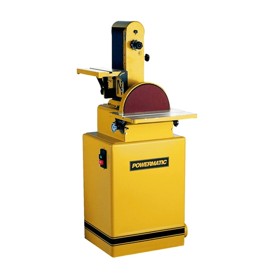
Combination belt/disc sander
Hide thumbs
Also See for 31A:
- Instruction manual & parts list (28 pages) ,
- Operating procedure (5 pages) ,
- Brochure (4 pages)
Table of Contents
Advertisement
Quick Links
This Manual is Bookmarked
Operating Instructions and Parts Manual
Combination Belt/Disc Sander
Model 31A
WALTER MEIER (Manufacturing) Inc.
427 New Sanford Road
LaVergne, Tennessee 37086
Part No. M-0460267
Ph.: 800-274-6848
Revision H 11/09
www.powermatic.com
Copyright © 2009 Walter Meier (Manufacturing) Inc.
Advertisement
Table of Contents

Related Manuals for Powermatic 31A


Summary of Contents for Powermatic 31A
- Page 1 This Manual is Bookmarked Operating Instructions and Parts Manual Combination Belt/Disc Sander Model 31A WALTER MEIER (Manufacturing) Inc. 427 New Sanford Road LaVergne, Tennessee 37086 Part No. M-0460267 Ph.: 800-274-6848 Revision H 11/09 www.powermatic.com Copyright © 2009 Walter Meier (Manufacturing) Inc.
-
Page 2: Warranty And Service
This warranty covers only the initial purchaser of the product. WHAT IS THE PERIOD OF COVERAGE? The general POWERMATIC warranty lasts for the ti m e period specified in the product literature of each product. WHAT IS NOT COVERED? The Five Year Warranty does not cover products used for commercial, industrial or educational purposes. Products with a Five Year Warranty that are used for commercial, industrial or education purposes revert to a One Year Warranty. -
Page 3: Table Of Contents
Guide to Sanding Belts and Discs ...................... 20 Troubleshooting ..........................21 Replacement Parts ........................... 21 Parts List: 31A Stand Assembly (1PH) .................... 22 31A Stand Assembly (1PH) ......................23 Parts List: 31A Stand Assembly (3PH) .................... 24 31A Stand Assembly (3PH) ......................25 Parts List: 31A Sander Body Assembly ................... -
Page 4: Warning
Make certain the work area is well lighted and that a proper exhaust system is used to minimize dust. Powermatic recommends the use of anti-skid floor strips on the floor area where the operator normally stands and that each machine’s work area be marked off. - Page 5 Misuse. Do not use this Powermatic sander for other than its intended use. If used for other purposes, Powermatic disclaims any real or implied warranty and holds itself harmless for any injury or damage which may result from that use.
-
Page 6: Introduction
Net Weight (lbs.) ............... 247..........247 Shipping Weight (lbs.) ............... 275..........275 *NOTE: For 460V operation, magnetic switch (part no. 31A-MSA-2) must be purchased separately and installed. A qualified electrician is recommended. The above specifications were current at the time this manual was published, but because of our policy of continuous improvement, Walter Meier reserves the right to change specifications at any time and without prior notice, without incurring obligations. -
Page 7: Grounding Instructions
Grounding Instructions All grounded, cord-connected tools: In the event of a malfunction or breakdown, grounding provides a path of least resistance for electric current to reduce the risk of electric shock. This tool is equipped with an electric cord having an equipment-grounding conductor and a grounding plug. -
Page 8: Dimensions
Dimensions Figure 2 On-Off Switch Padlock The single-phase model of the 31A Sander is equipped with a push-button switch that will accept a safety padlock (not included). To safeguard your machine from unauthorized operation and accidental starting by young children, the use of a padlock is highly recommended –... -
Page 9: Unpacking
Miter Gauge Assembly Unpacking Bag of Fasteners, contains: Socket Head Cap Screws, M10x25 – AA Open shipping container and check for shipping damage. Report any damage immediately to Hex Head Screws, M8 x 25 – BB your distributor and shipping agent. Do not Lock Washers, M8 –... -
Page 10: Assembly
Assembly Tools required: wrenches – 10, 13 and 17mm hex (Allen) wrench – 8mm Cross-point screwdriver Installing Sander on Stand Refer to Figure 5: 1. If the machine is to be secured to the floor, use high quality lag screws through the four holes inside the bottom of the stand. -
Page 11: Installing And Tracking Abrasive Belt
Installing and Tracking Abrasive Belt To install the abrasive belt, proceed as follows Refer to Figures 7 and 8: 1. Loosen the knob (A) and swing the belt end guard (B) out of position. 2. Remove the side cover by unscrewing the two knobs holding it, and sliding the tabs of the side cover out of the slots of the sander. -
Page 12: Installing Abrasive Disc
2. Insert the two M10x25 socket head cap screws (AA), with two M10 flat washers (EE), through the fence base and into the threaded holes on the pivot plate, as shown in Figure 9. 3. Tighten the screws with an 8mm hex wrench. -
Page 13: Dust Outlet And Cord Plate
(single phase model) prevent electrical shock and possible fatal injury. The 31A Sander is equipped with either a single phase 115/230 volt motor (pre-wired 115V); or a three phase 230/460 volt motor (pre-wired 230V). -
Page 14: Extension Cords
1. Replace the current contactor with the 460V voltage resulting loss power magnetic contactor (part no. 31A-MSA-2; overheating. purchased separately). Use the chart in Figure 14 as a general guide in 2. Re-connect the incoming leads to the motor choosing the correct size cord. If in doubt, use in accordance with 460 volt operation, as the next heavier gauge. -
Page 15: Adjustments
Adjustments Before putting power to the sander, inspect the machine thoroughly. Check to ensure that all screws are tight, all mechanical functions work freely, belt runs freely and tracks properly, and the disc runs freely, does not come into contact with the guard or table, and the abrasive remains firmly adhered to the sander’s metal disc. -
Page 16: Work Stop
A zero-degree stop screw (D, Figure 17) is located behind the disc. The block should be set for quick placement of the table to the zero position (90 degree table). The block must be swung out of position for the table to be tilted downward. -
Page 17: Operation
Operation The belt and disc sander can be equipped with a variety of abrasives and grit sizes to handle a wide variety of materials, from soft woods to hardened steel. It can be used to rapidly remove material and produce a mirror finish. Using various types of fixtures, they can be used to sand template forms, angles, freehand contours, and flats on edges, surfaces and ends. -
Page 18: Types Of Operations
The chart on page 20 lists the various grits and materials used and lists the grit symbols. It is generally better to start with a slightly coarser abrasive than would seem practical because it will give faster material removal, generate less heat, and will sand more freely. -
Page 19: Maintenance
Use SAE No. 10 Oil on these: internal threads of table locking wheels (A, Figure 16) Figure 27 belt arm index pin (shown in Figure 5) All bearings used on the Model 31A Sander are sealed for life and require no lubrication. -
Page 20: Guide To Sanding Belts And Discs
Guide to Sanding Belts and Discs... -
Page 21: Troubleshooting
Replacement parts are listed on the following pages. To order parts or reach our service department, call 1-800-274-6848, Monday through Friday (see our website for business hours, www.powermatic.com). Having the Model Number and Serial Number of your machine available when you call will allow us to... -
Page 22: Parts List: 31A Stand Assembly (1Ph)
29 .... 31A-98 ....Power Cord ............1PH ......1 30 .... 31A-99 ....Hex Nut............M10 ......1 31 .... 31A-21 ....Pan Head Screw w/ Flange .......M6 x 12 ...... 4 32 .... TS-1523041 ....Socket Set Screw ..........M6 x 12 ...... 1 33 .... 31A-100 ....Pan Head Screw..........M4 x 5......2 34 .... -
Page 23: Stand Assembly (1Ph)
31A Stand Assembly (1PH) -
Page 24: Parts List: 31A Stand Assembly (3Ph)
23 ... TS-1540061 ....Hex Nut............M8 ......4 24 .... 31A-99 ....Hex Nut............M10 ......1 25 .... 31A-21 ....Pan Head Screw w/ Flange .......M6 x 12 ...... 4 26 ... TS-1523041 ....Socket Set Screw ..........M6 x 12 ...... 1 27 .... 31A-100 ....Pan Head Screw..........M4 x 5......2 28 .... -
Page 25: Stand Assembly (3Ph)
31A Stand Assembly (3PH) -
Page 26: Parts List: 31A Sander Body Assembly
19 .... 31A-19 ....Index Pin .................... 1 20 .... 31A-20 ....Knob ..............M6 x 12 ...... 3 21 .... 31A-21 ....Pan Head Screw w/ Flange .......M6 x 12 ...... 3 22 .... 31A-22 ....Locking Handle..........M10 x 1.25P ....1 23 .... 31A-23 ....Lock Handle .............M10 x 45 ....1 24 .... - Page 27 58 .... 31A-52 ....Lock Washer ............M16 ......2 59 .... 31A-53 ....Hex Head Flange Bolt ........M6 x 20 ...... 4 60 .... 31A-54 ....Lock Washer ............M6 ......2 61 .... 31A-55 ....Hex Head Bolt ..........M6 x 8......2 62 .... TS-1504041 ....Socket Head Cap Screw ........M8 x 20 ...... 2 63 ....
-
Page 28: 31A Sander Body Assembly
31A Sander Body Assembly... -
Page 29: Electrical Connections (1 Phase)
Electrical Connections (1 Phase) -
Page 30: Electrical Connections (3 Phase)
Electrical Connections (3 Phase) - Page 32 WALTER MEIER (Manufacturing) Inc. 427 New Sanford Road LaVergne, Tennessee 37086 Phone: 800-274-6848 www.powermatic.com www.waltermeier.com...