Table of Contents
Advertisement
Advertisement
Table of Contents

Related Manuals for Powermatic DDS-225


Summary of Contents for Powermatic DDS-225
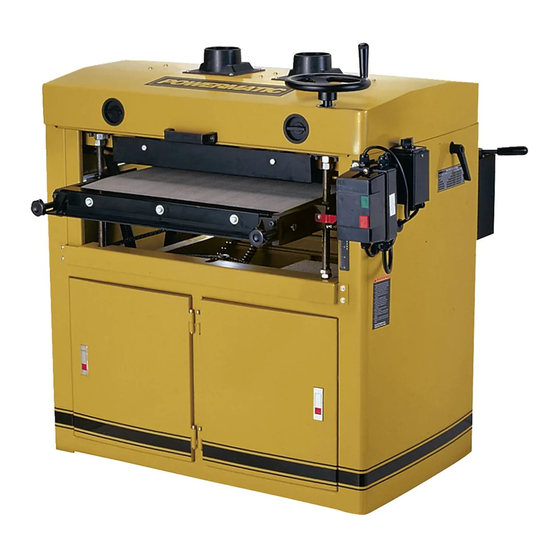
- Page 1 This Manual is Bookmarked Operating Instructions and Parts Manual Dual Drum Sander Model: DDS-225, DDS-237 WMH TOOL GROUP 2420 Vantage Drive Elgin, Illinois 60123 Part No. M-0460278 Ph.: 800-274-6848 Revision D1 04/07 www.wmhtoolgroup.com Copyright © 2007 WMH Tool Group, Inc.
-
Page 2: Warranty And Service
This warranty covers only the initial purchaser of the product. WHAT IS THE PERIOD OF COVERAGE? The general POWERMATIC warranty lasts for the time period specified in the product literature of each product. WHAT IS NOT COVERED? The Five Year Warranty does not cover products used for commercial, industrial or educational purposes. Products with a Five Year Warranty that are used for commercial, industrial or education purposes revert to a One Year Warranty. -
Page 3: Table Of Contents
Parts – DDS-225 Sander ... 20 Drum Assembly – DDS-225 ... 20 Conveyor Assembly – DDS-225... 22 Motor & Cabinet Assembly – DDS-225 ... 24 Gearbox Assembly – DDS-225 Drum ... 27 Parts – DDS-237 Sander ... 29 Drum Assembly – DDS-237 ... 29 Conveyor Assembly –... -
Page 4: Warnings
4. This drum sander is designed and intended for use by properly trained and experienced personnel only. If you are not familiar with the proper and safe operation of a drum sander, do not use until proper training and knowledge have been obtained. - Page 5 29. If the operator leaves the machine area for any reason, the sander should be turned "off" and come to a complete stop before his departure. In addition, if the operation is complete, he should clean the sander and the work area.
-
Page 6: Features
Features Specifications Model Number... DDS-225 ... DDS-237 ... DDS-237 Stock Number ...1791290 ... 1791320 ... 1791321 Main Motor ...see below ...see below ...see below Main Motor Speed (RPM) ...1,725 ... 1,725 ... 1,725 Electrical Controls ...see below ...see below ...see below Conveyor Motor...see below ...see below ...see below... -
Page 7: Unpacking
Shipping Contents Note 1: Some parts are inside a box in the cabinet. Note 2: Models DDS-225 and DDS-237 Drum Sanders come from the factory with the first set of abrasive strips installed with 80 grit sandpaper on the front drum and 100 grit on the rear drum. -
Page 8: Assembly
The machine must be properly grounded to help prevent electrical shock and possible fatal injury. A power plug is not provided with the DDS-225 or DDS-237 Dual Drum Sander. You may either connect the proper UL/CSA listed plug or “hardwire”... -
Page 9: Abrasive Paper Installation
Note: If the wedge sticks, use a flat head screwdriver as leverage to free it. 3. Cut a length of the Ready-To-Cut abrasive strip (12' for the DDS-225, 16' 5" for the DDS-237). This will be enough to cover one drum. -
Page 10: Adjustments
Note: It is important that the dial setting be identical at both ends of the drum. 4. Tighten the locking levers (Fig. 8) by rotating clockwise, before operating the sander. Note: The locking levers are spring loaded – you can move the handle to any position by pulling out on the lever, rotating it on the hub, then releasing. -
Page 11: Pressure Rollers
1/16”. A limit plate (Fig. 11) is mounted to the front of the sander. If the table has been set too high, the workpiece will contact this plate and a limit switch will shut off the conveyor table. If this happens, re- position the table and restart the machine. -
Page 12: Lead Screw Thread Clearance
4. Insert a tool, such as a hex wrench or screwdriver, through the hole on top of the leadscrew (Fig 13) at that corner of the table that is lowest. 5. Turn the leadscrew clockwise to raise the table. 6. When the adjustment is complete, install the chain over the four sprockets, and over the chain tensioner roller. -
Page 13: Conveyor Belt
Conveyor Belt Conveyor belt tension and tracking adjustments may occasionally be necessary during break-in and normal operation to compensate for belt stretching. Adjust the tension of the conveyor belt by turning the knobs (Fig. 15) clockwise to increase tension, counterclockwise to decrease tension. -
Page 14: Pulley Alignment
Pulley Alignment The drum and motor pulleys must be in line so that the belts are straight. To check this: Place a straight edge, such as a metal ruler, against the flat sides of the motor pulley and a drum pulley (Fig. 18). If the straight edge does not lie flush on the flat sides of the pulleys, loosen the set screw on the motor pulley (Fig. -
Page 15: Maintenance
Use a good quality gear oil. After every 2,500 hours, completely drain and refill gearbox. Operations Basic Operation The basic operating procedure for the DDS-225 is as follows: Set depth of cut. Start drums. Start conveyor and select feed rate. -
Page 16: Multiple-Piece Sanding Runs
Then progressively work toward finer grits. This means if you are using two different grits on your DDS-225 dual drum sander, the coarser grit should always be placed on the front drum. - Page 17 results, never skip more than one grit grade when progressing through a sanding sequence. For fine work, such as furniture, try not to skip any grit grades during the sanding process. In general, premium quality abrasives will produce a better finish with a less noticeable scratch pattern.
-
Page 18: Maintenance Checklist
Maintenance Checklist Note: See also the Maintenance section on page 15. Work area around machine marked off clearly. Non-skid floor strips in area where operator normally stands. Inspect entire machine for loose bolts, nuts, screws. Tighten and replace as necessary. Clean conveyor and drum areas, removing sawdust and chips with compressed air or a Troubleshooting... -
Page 19: Mechanical & Electrical Problems
If amp setting is correct then there is probably a loose electrical lead. Check amp setting on the motor starter. 4. Verify that sander is on a circuit of correct size. If circuit size is correct, there is probably a loose electrical lead, Check amp settings on motor starter. -
Page 20: Parts - Dds-225 Sander
Parts – DDS-225 Sander Drum Assembly – DDS-225 Index No. Part No. Description Size 1 ...DDS225-101 ...Rear Drum..1 2 ...DDS225-102 ...Abrasive Fastener-Right ..2 3 ...DDS225-103 ...Abrasive Fastener-Left..2 4 ...DDS225-104 ...Spring..2 5 ...DDS225-105 ...Locking Wedge ..4 6 ...TS-0561021 ...Hex Nut ... - Page 21 Drum Assembly – DDS-225 Index No. Part No. Description Size 54 ...DDS225-154 ...Front Drum ..1 55 ...TS-1521021 ...Socket Set Screw... M4 x 6 ... 4 56 ...DDS225-156 ...Roll Pin... ∅2 x 8mm ... 2 57 ..Abrasive (see Optional Accessories on page 38)
-
Page 22: Conveyor Assembly - Dds-225
Conveyor Assembly – DDS-225 Index No. Part No. 1 ...DDS225-201 ...Table ..1 2 ...DDS225-202 ...Support Bracket, Left-Front..1 3 ...DDS225-203 ...Support Bracket, Right-Front ..1 4 ...DDS225-204 ...Support Bracket, Left-Rear ..1 5 ...DDS225-205 ...Support Bracket, Right-Rear..1 6 ...DDS225-206 ...Leadscrew Holder, Right-Front... - Page 23 Conveyor Assembly – DDS-225 Index No. Part No. Description Size 56 ...TS-081C022...Screw ... #10-24 x 3/8... 8 57 ...DDS237-260 ...Boot..4 58 ...DDS237-258 ...Special Washer..4 59 ...TS-0208021 ...Socket Head Cap Screw... 5/16-18 x 1/2... 8 60 ...DDS225-260 ...Nylon Washer..4...
-
Page 24: Motor & Cabinet Assembly - Dds-225
Motor & Cabinet Assembly – DDS-225 Index No. Part No. Description Size 1 ...DDS225-301 ...Cabinet..1 2 ...DDS225-302 ...Support Bracket-Front..1 3 ...DDS225-303 ...Support Bracket-Rear ..1 4 ...DDS225-304 ...Motor Plate..1 5 ...DDS225-305 ...Motor Pulley ..1 6 ...DDS225-306 ...Motor ... - Page 25 Motor & Cabinet Assembly – DDS-225 Index No. Part No. Description Size 59 ...DDS225-359 ...Rear Cover..1 60 ...DDS225-360 ...Self Tapping Screw... #10 x 1/2 ... 2 61 ...TS-069204 ...Flat Washer... SAE #10... 2 62 ...DDS225-362 ...Lock Piece..2 63 ...DDS225-363 ...Plastic Nut ...
- Page 26 Motor & Cabinet Assembly – DDS-225...
-
Page 27: Gearbox Assembly - Dds-225 Drum
Gearbox Assembly – DDS-225 Drum Index No. Part No. 1 ...DDS225-401 ...Gearbox Body ..1 2 ...TS-0720071 ...Lock Washer ... 1/4 ... 4 3 ...TS-0207071 ...Socket Head Cap Screw... 1/4-20 x 1-1/4... 4 4 ...DDS225-404 ...Drain Plug ..1 5 ...BB-626VV ...Ball Bearing... - Page 28 Gearbox Assembly – DDS-225 Drum...
-
Page 29: Parts - Dds-237 Sander
Parts – DDS-237 Sander Drum Assembly – DDS-237 Index No. Part No. Description Size 1 ...DDS237-101 ...Rear Drum..1 2 ...DDS225-102 ...Abrasive Fastener-Right ..2 3 ...DDS225-103 ...Abrasive Fastener-Left..2 4 ...DDS225-104 ...Spring..2 5 ...DDS225-105 ...Locking Wedge ..4 6 ... - Page 30 Drum Assembly – DDS-237 Index No. Part No. Description Size 55 ...TS-1521041 ...Socket Set Screw... M4 x 10 ... 4 56 ...DDS225-156 ...Roll Pin... ∅2 x 8mm ... 2 57 ...TS-0720091 ...Lock Washer ... 3/8 ... 8 58 ...TS-0100041 ...Hex Cap Screw ... 1/2-13x 1-1/4... 4...
-
Page 31: Conveyor Assembly - Dds-237
Conveyor Assembly – DDS-237 Index No. Part No. 1 ...DDS237-201 ...Table ..1 2 ...DDS225-202 ...Support Bracket, Left-Front..1 3 ...DDS225-203 ...Support Bracket, Right-Front ..1 4 ...DDS225-204 ...Support Bracket, Left-Rear ..1 5 ...DDS225-205 ...Support Bracket, Right-Rear..1 6 ...DDS225-206 ...Leadscrew Holder, Right-Front... - Page 32 Conveyor Assembly – DDS-237 Index No. Part No. Description Size 58 ...DDS237-258 ...Special Washer..4 59 ...DDS237-259 ...Upper Bracket ..4 60 ...DDS237-260 ...Boot..4 61 ...TS-081C022...Screw ... #10-24 x 3/8... 8 62 ...TS-0680021 ...Flat Washer... 1/4 ... 8 63 ...DDS225-336 ...Hex Head Screw ...
-
Page 33: Motor And Cabinet Assembly - Dds-237
Motor and Cabinet Assembly – DDS-237 Index No. Part No. 1 ...DDS237-301 ...Cabinet..1 2 ...DDS237-302 ...Support Bracket-Front..1 3 ...DDS237-303 ...Support Bracket-Rear ..1 4 ...DDS237-304 ...Motor Plate..1 5 ...DDS237-305 ...Motor Pulley ..1 6 ...DDS237-306 ...Motor ... - Page 34 82 ...DDS225-382 ...Reverse Switch (for 7-1/2HP, 1Ph, 230V) ..1 ...DDS237-382 ...Reverse Switch (for 10HP, 3Ph, 230/460V) ..1 83 ...DDS225-383 ...Switch Bracket ..1 84 ...DDS225-384 ...Strain Relief..2 85 ...DDS237-385 ...Powermatic Logo ..1 Description Size...
- Page 35 Motor and Cabinet Assembly – DDS-237 Index No. Part No. Description Size 86 ...DDS237-386 ...I.D. Label (not shown)..1 87 ...TS-2361101 ...Lock Washer ... M10 ... 1 88 ...DDS237-388 ...Pad..4 89 ...DDS237-389 ...Strain Relief..2...
-
Page 36: Gearbox Assembly - Dds-237
Gearbox Assembly – DDS-237 Index No. Part No. 1 ...DDS225-401 ...Gearbox Body ..1 2 ...TS-0720071 ...Lock Washer ... 1/4 ... 4 3 ...TS-0207071 ...Socket Head Cap Screw... 1/4-20 x 1-1/4... 4 4 ...DDS225-404 ...Drain Plug ..1 5 ...BB-626VV ...Ball Bearing... - Page 37 Gearbox Assembly – DDS-237...
-
Page 38: Optional Accessories
Optional Accessories The optional accessories listed below are intended for use with DDS-225 and DDS-237 Drum Sanders. Ready-To-Cut Abrasive Strips Part No. Description Normal Use 60-9036 ...36 Grit Sandpaper...surfacing rough-sawn boards, stock and glue removal 60-9060 ...60 Grit Sandpaper...surfacing and dimensioning boards, truing warped boards 60-9080 ...80 Grit Sandpaper...surfacing, light dimensioning, removing planer ripples... -
Page 39: Wiring Diagram
Wiring Diagram DDS-225 Sander... - Page 40 DDS-237 Sander – 7.5HP, 1Ph, 230V BLACK WHITE 250VAC 250MFD 250VAC 250MFD 450VAC 50UF REVERSING SWITCH FRONT BACK LIMITED SWITCH 350VAC 10UF...
- Page 41 DDS-237 Sander – 10HP, 3Ph, 230V BLACK LIMITED SWITCH BLACK WHITE REVERSING SWITCH BACK WHITE FRONT...
- Page 42 DDS-237 Sander – 10HP, 3Ph, 460V BLACK LIMITED SWITCH BLACK WHITE REVERSING SWITCH BACK WHITE FRONT...
- Page 43 Notes...
- Page 44 WMH Tool Group 2420 Vantage Drive Elgin, Illinois 60124 Phone: 800-274-6848 www.wmhtoolgroup.com...