
Related Manuals for Powermatic BD31A


Summary of Contents for Powermatic BD31A
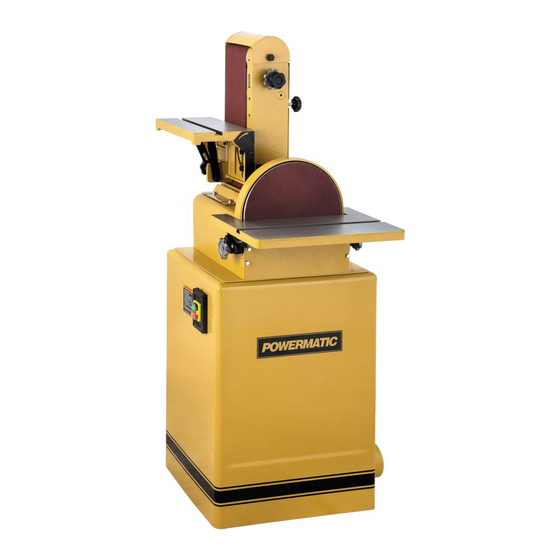
- Page 1 BELT & DISC SANDER Model BD31A Instruction Manual & Parts List M-0460267 (800) 274-6848 www.powermatic.com...
- Page 2 This manual has been prepared for the owner and operators of a Powermatic Model BD31A Belt & Disc Sander. Its purpose, aside from machine operation, is to promote safety through the use of accepted correct operating and maintenance procedures. Completely read the safety and maintenance instructions before operating or servicing the machine.
-
Page 3: Table Of Contents
TABLE OF CONTENTS Safety Rules................................ 4-5 Safety Decal ................................6 Specifications ................................7 Receiving ................................8 Installation & Assembly............................8 Electrical Connections............................8 Adjustments................................9 Abrasive Belt Installation ...........................9 Abrasive Belt Alignment ............................9 Platen Adjustment ............................10 Sanding Table Adjustment..........................10 Work Stop ...............................10 Belt Arm Positioning............................11 Changing Motor Voltage ..........................11 Operating the Sander ............................11 Template Forms..............................11 Fence/Table ..............................12... -
Page 4: Safety Rules
Make certain the work area is well lighted and that a proper exhaust system is used to minimize dust. Powermatic recommends the use of anti-skid floor strips on the floor area where the operator normally stands and that each machine’s work area be marked off. Provide adequate work space around the machine. - Page 5 Misuse. Do not use this Powermatic sander for other than its intended use. If used for other purposes, Powermatic disclaims any real or implied warranty and holds itself harmless for any injury or damage which may result from that use.
-
Page 6: Safety Decal
SAFETY: Decal for Model 31A Sander Familiarize yourself with the location and content of this decal on your machine. 31A-102... -
Page 7: Specifications
Fence size ............................13” W x 7-1/2” L Net weight ..............................246.4 lbs. NOTE: The above specifications were current at the time this manual was published, but because of our policy of continuous improvement, Powermatic reserves the right to change specifications without notice and without incurring obligations. -
Page 8: Receiving
(A mobile base for your sander is available from Powermatic – stock # 708221.) Mount the sander body (A) to the stand (B) with four M8 x 25 hex head screws, four M8 lock washers and four M8 flat washers as shown in Figure 3. -
Page 9: Adjustments
WARNING: Electrical wiring should be done by a qualified electrician. The machine must be properly grounded to help avoid electrical shock and associated hazards including possible death. ADJUSTMENTS Before putting power to the sander, inspect the machine thoroughly. Check to ensure that all screws are tight, all mechanical functions work freely, belt runs freely and tracks properly, and the disc runs freely and does not come into contact with the guard or table. -
Page 10: Platen Adjustment
Make final adjustments tracking momentarily starting and stopping the motor while at the same time adjusting the tracking screw (F), Figure 5, at the side of the belt arm. To lock the screw in place, rotate the tracking screw locking nut (G) against the belt arm. -
Page 11: Belt Arm Positioning
BELT ARM POSITIONING Your sander is equipped with a shot pin arrangement to lock the belt arm in 0-degree, 45-degree, and 90 degree positions. To position the belt, loosen the locking handle (A) shown in Figure 10. Pull out on the shot pin (B), shown in Figure 11, and swing the belt arm into the desired position. -
Page 12: Fence/Table
FENCE/TABLE The fence attachment is used with the belt sander and can be positioned alternately as a table (with the belt arm in upright position) or as a fence (with the belt arm in horizontal position). The fence attachment surface has a slot for a mitre gauge when the attachment is used as a table. -
Page 13: Types Of Operations
Miters and compound miter cuts can be sanded using the table and the optional miter gauge (available from your Powermatic dealer). Special fixtures can also be designed to use on the table for circular and form sanding. -
Page 14: Grit Comparison Chart
GRIT COMPARISON CHART Accessories SANDING BELTS SANDING DISCS 57617110 6” x 48” Sanding Belt, 24 Grit, Closed Coat* 57698525 12” Sanding Disc, 36 Grit 57617210 6” x 48” Sanding Belt, 40 Grit, Closed Coat 57698650 12” Sanding Disc, 50 Grit 57617410 6”... -
Page 15: Troubleshooting
TROUBLE SHOOTING for Model 31A Sander Problem Cause Solution Machine fails to start. 1. Fuses blown. 1. Replace fuses. 2. Faulty switch. 2. Replace switch. 3. Bad motor. 3. Replace motor. 4. Not connected to power source. 4. Check connection. 5. -
Page 16: Parts Lists & Exploded Views
PARTS LIST: Body Assembly (Model 31A Sander) Part No. Description Quantity 31A-1 Cast Base ....................... 1 31A-2 Dust Chute (Disc).................... 1 31A-3 Sanding Disc....................1 31A-4 Disc Table....................... 1 31A-5 Trunnion ......................2 31A-6 Stop Bracket ..................... 1 31A-7 Trunnion Holder ....................2 31A-8 Set Screw, M10 x 55.................. - Page 17 Part No. Description Quantity 31A-51 Set Screw, M6 x 8 ...................1 31A-52 Lock Washer, M16 ..................2 31A-53 Hex Head Flange Bolt, M6 x 20...............4 31A-54 Lock Washer, M6 ....................2 31A-55 Hex Head Bolt, M6 x 8 ..................2 TS-1504041 Socket Head Cap Screw, M8 x 20 ..............2 TS-1551051 Lock Washer, 8mm ..................2 31A-56 Hex Nut, M16 x 2 (L.H.
-
Page 18: Body Assembly
Body Assembly (Model 31A Sander) - Page 19 PARTS LIST: Stand Assembly (Model 31A Sander) Part No. Description Quantity 31A-78 Stand ......................1 31A-79 Dust Outlet ......................1 31A-80 Motor Pulley ....................1 31A-81 Motor, 1.5 HP, 1 Ph, 115/230V, 12/6 A, 1750 RPM ........1 31A-82 Door ........................1 31A-83 Door Latch Assembly ..................1 31A-84 Motor Mounting Bracket ..................1 31A-85...
-
Page 20: Stand Assembly
Stand Assembly (Model 31A Sander) -
Page 21: Electrical Schematics
ELECTRICAL SCHEMATIC (Model 31A Sander) - Page 22 ELECTRICAL SCHEMATIC (Model 31A Sander)
- Page 23 Locating the stock number of the part(s) required from your parts manual will also expedite your order. Phone No.: (800) 274-6848 Fax No. (800) 274-6840 If you are calling from Canada, please call 800-238-4746 E-mail: powermatic@wmhtoolgroup.com Website: www.powermatic.com...
- Page 24 07/02 WMH Tool Group P.O. Box 1349 Auburn, WA 98071-1349 Phone:(800) 274-6848 Fax: (800) 274-6840 E-mail: powermatic@wmhtoolgroup.com Website: www.powermatic.com Powermatic ALL RIGHTS RESERVED...