Table of Contents
Advertisement
Quick Links
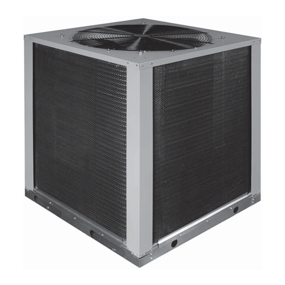
S5BP SERIES
USER'S MANUAL / INSTALLATION INSTRUCTIONS
R410A SPLIT SYSTEM AIR CONDITIONER - 3 PHASE
Please read this information thoroughly and become familiar with the capabilities and
use of your appliance before attempting to operate or maintain this unit. Keep this
literature where you have easy access to it in the future. If a problem occurs, check the
instructions and follow recommendations given. If these suggestions don't eliminate
your problem, call your servicing contractor.
These instructions are primarily intended to assist qualifi ed individuals experienced in
the proper installation of this appliance. Some local codes require licensed installation/
service personnel for this type of equipment. Please read all instructions carefully before
starting the installation.
IMPORTANT
DO NOT DESTROY. PLEASE READ CAREFULLY AND
KEEP IN A SAFE PLACE FOR FUTURE REFERENCE.
11.2 EER
Advertisement
Table of Contents

Related Manuals for Nordyne S5BP Series


Summary of Contents for Nordyne S5BP Series
- Page 1 S5BP SERIES 11.2 EER USER’S MANUAL / INSTALLATION INSTRUCTIONS R410A SPLIT SYSTEM AIR CONDITIONER - 3 PHASE IMPORTANT Please read this information thoroughly and become familiar with the capabilities and use of your appliance before attempting to operate or maintain this unit. Keep this literature where you have easy access to it in the future.
-
Page 3: Table Of Contents
USER INFORMATION WARRANTY INFORMATION Important Safety Information ........4 A warranty certifi cate with full details is included with the Operating Instructions ..........4 air conditioner. Carefully review these responsibilities with Cooling Operation .............4 your dealer or service company. The manufacturer will not Heating Operation .............4 be responsible for any costs found necessary to correct Operating the Air Conditioner for Automatic... -
Page 4: Important Safety Information
USER INFORMATION IMPORTANT SAFETY INFORMATION The continuous indoor blower operation can be obtained with the thermostat system mode set in any position, Safety markings are used frequently throughout this including OFF. manual to designate a degree or level of seriousness and should not be ignored. -
Page 5: Important Safety Information
INSTALLER INFORMATION IMPORTANT SAFETY INFORMATION CAUTION: Please read all instructions before servicing this equipment. Pay attention to all safety warnings and any other special This unit uses refrigerant R-410A. DO NOT use notes highlighted in the manual. Safety markings are any other refrigerant in this unit. -
Page 6: Air Conditioner Installation
General Information TO BE UNOBSTRUCTED The S5BP series air conditioner is designed only for outdoor rooftop or ground level installations. This unit has been tested for capacity and effi ciency in accordance with A.R.I. Standards and will provide many years of safe and dependable comfort, providing it is properly installed and maintained. -
Page 7: Ground Level
Ground Level Connecting Refrigerant Tubing Between the Indoor Ground level installations must be located according to & Outdoor Unit local building codes or ordinances and these requirements: CAUTION: • Clearances must be in accordance with those shown in Figure 2 (page 6). This system uses R-410A refrigerant with POE •... -
Page 8: Electrical Wiring
ELECTRICAL WIRING connections in accordance with all applicable codes and ordinances. • Overcurrent protection must be provided at the branch WARNING: circuit distribution panel and sized as shown on the unit rating label and according to applicable local codes. To avoid risk of electrical shock, personal See the unit rating plate for minimum circuit ampacity injury, or death, disconnect all electrical power and maximum overcurrent protection limits. -
Page 9: Unbalanced 3-Phase Supply Voltage
Unbalanced 3-Phase Supply Voltage Thermostat Connections Voltage unbalance occurs when the voltages of all phases • Thermostat connections should be made in accordance of a 3-phase power supply are no longer equal. This with the instructions supplied with the thermostat and unbalance reduces motor effi... -
Page 10: Startup & Adjustments
START UP & ADJUSTMENTS 3. After approximately 5 minutes, verify the compressor and fan energize and the temperature of the discharge Pre-Start Check List Verify the indoor unit is level and allows proper air is cooler than the room temperature. condensate drainage. -
Page 11: Charging R410A Units In Ac Mode With Outdoor Temperatures Above 55° F
Remove refrigerant and repeat Steps 1 through 3 REPLACEMENT PARTS until the system is correctly charged. Replacement parts are available through all Nordyne distributors. Please have the complete model and serial number of the unit • If the pressure measured in Step 1 is less than the when ordering replacement parts. -
Page 12: Component Functions
COMPONENT FUNCTIONS Anti-Short Cycle Timer (ASCT) Low Pressure Switch (LPS) A protective short cycle timer is factory installed and located A low-pressure switch is factory-installed and located in in the control panel of the outdoor section. If power to the the suction line internal to the outdoor unit. -
Page 13: Electrical Information
ELECTRICAL INFORMATION 090C 090D 120C 120D Model Number 208-230V 460V 208-230V 460V S5BP- 920888 920889 920890 920891 PERFORMANCE DATA Gross Cooling Capacity (95 F) Btuh 92,400 92,400 121,700 121,700 Net Cooling Capacity - Btuh 90,000 90,000 117,000 117,000 A.R.I. Rated Airfl ow - C.F.M. 3,000 3,000 4,000... - Page 14 Figure 6. S5BP Wiring Diagram...
- Page 15 NOTE: C &W2 to be connected to electric heat. TO FIELD SUPPLIED DISCONNECT SINGLE STAGE HEAT/COOL THERMOSTAT C G Y BLOWER MOTOR FREEZESTAT GREEN BROWN BLACK See Note BLACK TERMINAL BOARD AIR HANDLER SECTION OUTDOOR SECTION SINGLE STAGE HEAT/COOL THERMOSTAT- NO ECONOMIZER NOTES: 1.
- Page 16 S5BP CHARGING CHARTS - COOLING ONLY Application Notes on the Use of Charging Charts • This equipment’s cooling system contains refrigerant under high pressure. Always use safe and environmentally sound methods when handling refrigerant handling or servicing the unit. Review the factory literature and safety warnings prior to servicing.
-
Page 17: Cooling Charging Charts
S5BP Charging Chart - Cooling 7.5 Ton Split System A.C. w/ B5SM-090* Indoor Air Handler Remove refrigerant when above curve Add refrigerant when below curve 100 105 110 115 120 125 Liquid Temperature (° F) Figure 8. Charging Chart for 7.5 Ton Units S5BP Charging Chart - Cooling 10 Ton Split System AC w/ B5SM-120* Indoor Air Handler Remove refrigerant when above curve... -
Page 20: Installation / Performance Checklist
INSTALLATION/PERFORMANCE CHECK LIST REFRIGERATION SYSTEM: INSTALLATION ADDRESS: Was unit given 24 hr warm up period for crankcase heaters? CITY ________________________ STATE ________________ Stage-1 Liquid Pressure (high side) ________________________ UNIT MODEL # ________________________________________ Stage-1 Suction Pressure (low side) ________________________ UNIT SERIAL # _______________________________________ Has the owner’s information been Unit Installed Minimum clearances per reviewed with the customer?